|
LabGuy's World:
What's New, LabGuy?
If making multiple visits to this page, on the same day, try pressing the shift key while clicking reload page to see the absolute latest updates. Merry Christmas. My best friend, Joe, has loaned me a very good analog oscilloscope. So, the electronics projects are back in business. My vendor has given me a quote of $1,200 for a replacement of my Tektronix TDS744A scope. Apparently, parts are not available to repair it. A spare grand is not in my budget. It was a great scope while it lasted. Speaking of my iconoscope camera TV project, I purchased a box of antique vidicon yokes from Ebay. The yokes are not in very good shape. But, there is a fair amount of Mu metal wrapped around them. That's worth far more than the copper in the coils. (which is not without value also). After getting feedback from the discussion group, it was concluded that Mu metal was required to shield my 5527 iconscope. The video amplifier is seeing only noise. That was the long running theory. But again! I discovered a significant error in my scan amplifier design while demonstrating my electrostatic CRTs. The same circuit I use in the iconoscope camera. The problem is immense gain. Any input is amplified to the rails. Not good for scanning. So, that camera may have been working with a one point four inch target and a ten inch scan raster. This would also explain the lack of a video signal, noise or not. You can see the progress of my scanning circuits on the [Electrostatic Cathode Ray Tubes] project page. So, those are now two new possible paths of exploration in getting my Tiny Ike up and running. I've been making good headway with the little cathode ray tubes despite the breakdown of my Tektronix TDS-744A digital oscilloscope. (Still no word from the vendor on cause of failure or cost of repair.) I successfully fired up the super rare 3UP1 and several 1DP1s and RCA 913s tiny CRTs. Was able to solve the problems associated with shared pin electrodes and tried single ended deflection for the first time. See all of this marvelous work on the [Electrostatic Cathode Ray Tubes] project page. I purchased a Cossor 1CP1 one inch CRT from Ebay. Then bought an 8 pin loctal tube socket to match. Loctal was developed for very early automobile radios. It is very much like the normal octal socket except with a much higher insertion force to keep the tube from vibrating out of the socket. The second benefit was the loctal tubes have pins mounted in the glass envelope like later subminiature and compactron tubes. With the normal octal tube base, the wire leads were soldered into the pins held by a bakelite cup. These wires also tended to fail under the high vibration, heat and humidty foundin cars and trucks. The glass evelope was glued into the bakelite cup and this was also another failure point and cost item in production. MERRY CHRISTMAS! Last evening, I received an email from Mr. Alan Lancendorfer who used to work for Echo Science Corp. He provided some excellent documentation on Arvin/Echo products of the late 1960s and early 70s. Lots of wideband instrumentation recorders that were also capable of recording and reproducing video as well. Will post all of the info soon. Bought a Sparkfun Scope Clock kit. It arrived last evening and was immediately connected to my Tek 606B XYZ scope and to the Eric Schlaepfer CRT driver boards. In both cases, it worked pretty good. Just before bed time, I realized that the board did have a Z axis output afterall. Not well documented. The displays were just a tad smeary because of the absence of beam blanking. Will put in those improvements this evening and give it another try. Updates to the electrostatic CRT page then. The Tektronix TDS744A digital phosphor oscilloscope goes in the shop today. Probably hundreds of dollars for the repair, even if it turns out to be a cheap fix! Could this happen at a worse time of year? (I somehow managed get my auto insurance payment to come due a couple of days before Christmas. That takes real genius.... I guess.) Waaaaaaa! My Tektronix TDS744A digital oscilloscope died!!! Waaaaaa! No O-scope, NO projects!! Waaaaaa! Stay tuned. The Tiny TV, Mark 2, Rev B is now considered completed. The self oscillation has some built in design issues and is prone to not starting. I will not be fixing this problem at this time. It's now making beautiful pictures on the Tektronix 606 XYZ display. Enjoy the final entry at the bottom of this page: [The Tiny TV Board, Mark 2]. Spent the day playing with photomultiplier tubes. Managed to get three completely different tubes operating in short order. A very good day. Read all about it on the [Photomultiplier Tubes Project page]. My first printed circuit boards have arrived today. Woo hoo! See them on the [Tiny TV Mk2 project] page. This is my video rasterizer project. It will be one of the sources of drive for my magnetic deflection experiments. I added two new-ish projects to [Labguy's Electronic Projects Page]. I added the Tiny TV Project and also moved the Video Frame Grabber project to this page. It has been sitting in obscurity under the obsolete documetnation page for too many years. Click this to see [The Tiny TV Project] or click this one to see [The Video Frame Grabber Project]. This web site was shut down for bandwidth violations. The video files were causing grief. So, I simply deleted all of them. Sorry. To see the videos, visit YouTube: [YouTube: Videolabguy Channel]. For some good news visit the [Cyclops (5AXP4) Project]. click through to part two if you are in a hurry. More project updates for today. The 5AXP4 / Cyclops project is almost completed today. Power was applied. Tests were performed. Shocks were experienced, of course! And to make it more interesting, I learned how easy it is to burn a hole through the front of a CRT. The beam was so hot, the color changed from P4 blue to heating element red! The on switch is also a panic switch. I slapped it off as fast as I could. A 1 or 2mm spot of phosphor, right in the center of the screen, is just gone! New rule. Never run Cyclops without deflection drive applied. The next phase of this sequence of projects is to build amplifiers that can receive voltage ramps and drive the deflection yoke current with high fidelity. I predict the vertical scan is going to be easier than horizontal. But, who can say just yet. That's what the experiments are all about. Stay tuned! A good deal of progress made on the 5AXP4 project yesterday. Added a great deal information to both the [5AXP4 Project] and to the [Color Flying Spot Scanner Project] pages. I fired up the 5AXP4 CRT and installed the deflection yoke. Tested both with DC current and the output of an audio amplifier. It works. It's alive! The big hold up now for poor old Labguy's anal rectitude (kinda rhymes with bad attitude, don't it?) is the shortage of 3D printed parts. Only one of four has been produced at this time. The two 3D printers, that I have access to, have both caught "digital ebola" and stopped working. OK. Not funny. Those poor printers work 24/7 when they are up. I am aware of individuals going into the office at 3am to change the print job! That's dedication. Expecting the 24 volt power supplies from Digi-key today or tomorrow. Then I can try to load test the EMCO 15KV power supply. I simply expect it to work. I have a dozen old surplus high voltage power supplies made by EMCO and they are 100% functional. The rarest quality, and this appeals to the old man in me, EMCO power supplies are made in the good old USA. God bless America. Where ever her body is buried now. Rest in peace. An update on why my projects appear to get started and then stop. No stopped project is actually dead. It is quite likely stuck because the next step for project one, might depend on reaching a particular milestone in project number three. In effect, the projects contain a huge number of inter-related links. Take the Tiny Ike camera. Though it is complete but not yet fully operational, it's production has given me the following building blocks applicable to future projects: Sync generator, scan (sawtooth) generator, electrostatic deflection amps. The Tiny Triniscope gives us a successful color matrix and a cool RGB beam splitter prism. The 5AXP4 project takes us to the >10KV realm of construction as well as bringing high power magnetic scanning to the game. The 5AXP4 itself is a poor choice for a video monitor or oscilloscope. It is not intended for continuous operation. It lacks an ion trap, aluminization and outer aquadag. It was intended as a test only picture tube. It is going to be perfect as my magnetic deflection test bed. The CRT will be fully powered independant of the scanning generator allowing any scan rate or type I desire, without screwing up a flyback transformer's resonance. This is the test bed for the Image Dissector camera(s) scanning circuits as well. With the addition of a sync and scan generator OR a vector display generator board, like a game of Asteroids(r) for instance, and we have a display test bed for developing the deflection yoke driver circuits. These circuits can then move on and can be used in the image dissector camera or the color flying spot scanner. See how this project supports and feeds the next? In addition to my own creations, my friend Eric Schlepfer has produced a set of [electrostatic CRT support boards] of which I have constructed three sets. These trun out to be perfect for running the CK1414 charactron monoscope tubes. Take Eric's boards, add the Tiny Ike sync generator, scan generators and video amp chain. Viola! One instant monoscope. Next, take the sync gen, scan gen, a wideband DC power amplifer (yet to be designed or copied), the photomultiplier tube secion of the image dissector camera, the color prism like used in the Tiny Triniscope, convert the Triniscope Matrix to convert RGB to YUV and add an NTSC encoder. Hook up the Sylvania SC4679B-PSP CRT and BANG! You've got a color flying spot scanner! Take all of the above, change the sync generator slightly and color encoder greatly and ZING BANG BOOM! CBS field sequential color flying spot scanner! My favorite! When I am not actively publishing to this site, I am most likely sucked into some project that has my absolute, blind to the universe, attention. So, now you know. Information is half the battle. Added more matrix theory information to my [color video matrix project] page. A couple of the inverse transform coeficeints are explained better. A couple of boo boos repaired. Created a new project today. See the [5AXP4 Project Page] page. It seemed I should find out if the 5AXP4 was operational before making any further plans around this tube. It is too serve as the visualizer test bed for my upcoming image dissector camera magnetic scanning systems. I was thinking that my coffee tasted like mud. Then I remembered it was fresh ground this morning! Nothing else news worthy to report. Yes. I'm still alive. Thanks for asking. Accomplished a lot this weekend. Completed the steel shelving in the new storage unit. Had to get two steel uprights cut down as they interferred with the roll of the roll up door. After a bit effort, the stars lined up and the right guy was finaly available at the vendor and he was able to find the blade for his Sawsall. Sometimes, the simple things can be the hardest to acomplish. I have begun moving VTRs only to the new location. The purpose is to inventory them and reorganize. In the end, I will only keep the VTRs, their immediate support accessories, tapes, reels and documentation. In the near future, there will be an open locker day where guests may come and pick out whatever there is. This will consist of cameras (hundreds), TBCs, cables, power supplies, video monitors, etc. With few exceptions, it will be if you can get it in your vehicle, it's yours for free. Stay tuned for an anounced date and location of this event. Some call Sunday the day of rest. Today, I can not disagree with that assessment. The shelving was 5/6 completed on Friday before the California heat made working in the locker any longer unbearable. A slight issue with the lenght of some steel shelving upright supports put the brakes on completing all six shelf units. These final two uprights are located just beneath the roll of the roll up door. On Friday, the vendor was able to supply two vertical uprights, to replace the two that were missing at delivery time. In that case, he gave me two that were already short enough to clear the rolled up door on the left side of the locker. His guy was not available at that time to cut the two too long pieces for me and has promised this will be completed for me tomorrow. With the help of my out-of-town guest yesterday, I was able to move a few VTRs into the new facility as a symbolic gesture of progress. If I can move two or three each day that I work on this, I should be done in... three months. Yikes! Need to rework that schedule before I go broke. Hoarding... er, um, I mean collecting anything in significant quantities can be very challenging. Organizing and storing the stuff is not as easy it may seem on the surface. Beyond my normal level of discipline. It is my long range goal to reorginize the collection and eventually flip it into a small business. I am finding the learning curve for this part of the process to be extremely steep, expensive and terrifying. Whoa! I just saw the very sad looking ghosts of George Orwell and Ayn Rand! (insert Twighlight Zone theme music here) Today's goal is to continue converting all of my pre-scanned literature into PDF files. Over the past four evenings, I have been able to generate over three hundred new PDF files. I have barely scratched the surface. I will be posting a detailed list of these documents, which includes advertising literature, operator and service manuals, price sheets, company line cards and even the original business plan for International Video Coporation! Labguy has the good stuff! He better after spending nearly $5,000 on literature alone over the past twelve years. Hence, the need to make the hobby begin to pay its own way. Who knew that following one's passions could get so expensive? Oh. Everyone but me?That figures. (wink) Tommorow is a national holiday for the USA. I have taken today and a couple of days next week off of work to deal with my storage situation. I did purchase industrial shelving to the tune of almost $1,800! It is slightly more than I need. But, it was truck load sale and, despite the high up front cost, a good value. I will have on the order of 324 square feet of shelving that can hold up several small sports cars! The shelves are to be delivered to the storage facility this morning. I was unable to find a helper on short notice. So, I will bite the bullet, and attempt to set these up by myself. Tomorrow is a day of rest for sure. Once set up, the old locker will be cherry picked and the best of the best will be moved to the new location. I will be performing a thorough inventory as each item is extracted, cleaned, photographed, catalogued and moved to the new facility. This may take up to two months because I can only work on this over the weekends, and all of those are not available to me. Those pesky day jobs and girlfriend obligations are always cutting into my fun, even though that is precisely what makes the fun possible and life worth living. Yes, this last paragraph is what we scientists call playful snark. I believe you should always learn at least one new thing every day. Another status update is highly likely later today or tomorrow. Don't touch that dial!
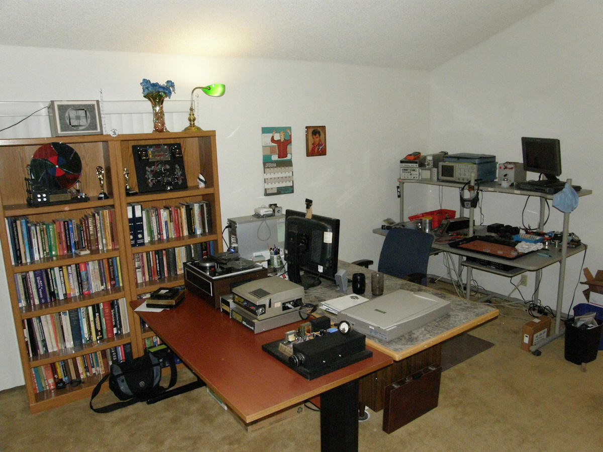
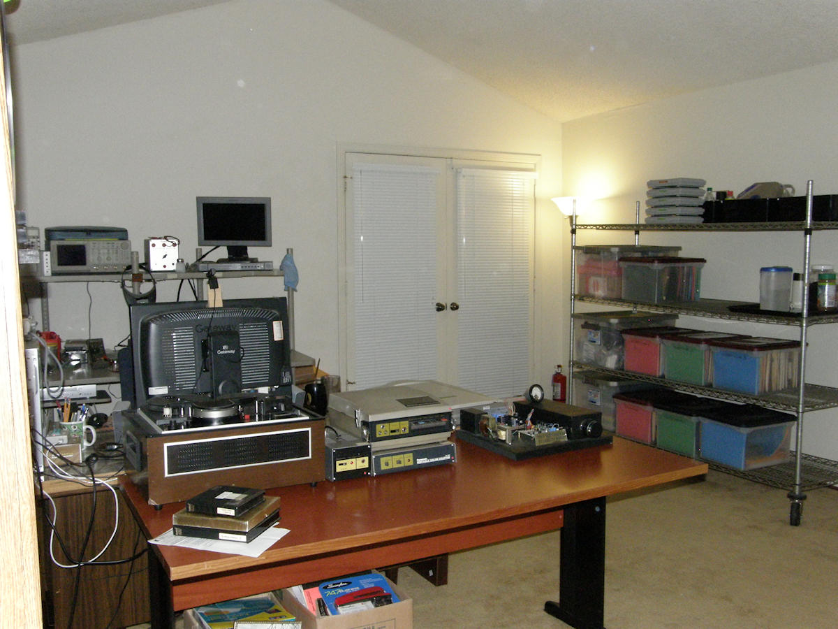
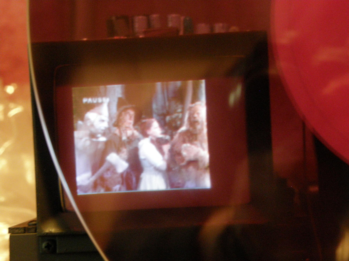
Take a gander at Labguy's NEW World. This is the work station from whence all current and future postings to this site will originate. You surely must agree that this is superior environment than I previously occupied. More light and more elbow room. The environment should also encourage me to be more disciplined in mess management! This is giving me ideas for additions to my electronics hobby page. An example of how to set up a good electronics hobby bench in limited space, for example. Since I had to move, this is a great time to reorganize the mountains of stuff I have accumulated over the past twelve years. If you are aware of anything in my vast collection that you covet, drop me a line and we can haggle over a price. A large amount of hardware, that is not on topic, is going to the recycler. The storage facilities are going to get the same treatment as well. Today's only major goal is to rent new locker space in preparation for sorting the original lockers and eliminating all the off topic material and trash. If anyone wants to come to San Jose, CA, and assist me on any weekend for the next four to eight weeks (up to the end of August), you can surely walk away with a lot of video goodies for your effort. Ultimately, the new locker will house only VTRs, totally unique video cameras, their immediate accessories and all of my documentation. The fact is, costs are spiraling out of control and I may be living hand to mouth again because of rent cost increases. This is requiring me to commit to the bold step of getting all of this done in a few short weeks and to overcome some obstacles simply by throwing HUGE amounts of money at the problem. Have you priced industrial shelving lately? Finally, if it is possible and practical, I may have to spin my hobby into self supporting specialty small business. I dread the ovreburden of excessive government regulations and the chilling effect it has on productive risk taking. Welcome to the fascist USSA of 2014. Hopefully, within a week or two, the projects will resume. I am still in the midst of moving and the details are everything. But, progress is happening at a steady, if somewhat slow, pace. I have the luxury of a slow move because I am only moving less than a mile and my previous room mate and land lord has generously allowed me all the time in the world... or until he sells his house! I have set up the new work bench and my computer desk in a manner that allows the iconoscope camera and test pattern light box to finally be conveniently positioned. Light box on desk, camera on bench. In the old environment, let's just say things were more awkward. There is still more specialized furniture to locate. I am going to get a stainless steel "bread rack" with dolly wheels. On this, I can store my parts inventory in 20 gallon plastic tubs with covers. This will be much easier to dust and to store. Details, details, details! My old room mate has given me a [Sony MEU-WX2] multiformat engine and a matching LMD monitor. It is compact enough for my bench and more powerful than I will ever need. It has composite and component video inputs as well as a D1 SDI input! The LCD monitor is 1920x1080, 16.5 inches on the diagonal. Like I said, more monitor than I can use. Perfect! This update will be my first upload from the new digs. Successfully moved my "glass" collection. All of my rare camera tubes and CRTs made the trip A-OK! Set up my book cases to highlight the Goldmark 1 and Tiny Triniscope projects. Much more stuff to move. Either to the new home or to storage.... I am still in the process of moving. I do a little every evening and the big stuff on the weekends. Mostly. The distance is only a mile. Plus my old landlord is allowing me to take all the time I need. This is going to continue for several more weeks. Cost of living strain forces me to relocate my storage facilities as well. A huge reorginization is planned for that time. By end of summer, the junk and acuumulated trash should be gone and only valid on topic materials will be stored in lower cost location. It looks like Labguy's World will have a petty decent lab bench at the new location. Not as much space as before. This will force me to be more efficient. All previously proposed electronics projects are still on the drawing board. These will benefit from being able to set up the new work area properly from the get go. Stay tuned. Getting my new lab ready. Purchased a jim dandy universal device programmer. This can program memory chips, logic arrays, microprocessors, etc.. I will be using it to can fixed test patterns into memory chips. The simplest analogy is that of the mechanism in a music box. A small drum covered with pins rotates passed the musical fingers. I use the memory chip in the same way to grind out repetative pulse patterns for things like video sync generators and other types of state machines. If it needs more than 8 outputs, you can run one or more memory chips in parallel. To hold a frame of monochrome EIA (U.S. B&W) video, it takes 307,200 bytes of memory. (640 pixels x 480 lines by 8 bits per pixel) I am using half megabyte flash proms for this job. Smaller memories will be used for things like my upcoming Arcuate Sweep generator for displaying mechanical TV properly on a CRT. To go with the programmer, I have installed visual basic and C++, and software to support the Arduino processor. My up coming projects are now becoming complex enough that I must install some form of intelligence. Switches and knobs are not going to make it any more. the completed project would be very large just to hold all the contorls. Tied to a computer via USB on the other hand.... I have plans for two separate monoscope video generator projects. One with a vacuum tube as the source, the other will be digital. The digital monoscope is made of a 19 bit counter, a flash memory chip, an analog to digital converter and some glue logic. It will grind out one test pattern indefinitely. Great for aligning monitors or just as a video source for sanity checks. It should be about the size of a pack of cards or a small transistor radio when it is done. Battery powered of course. Thinking out loud today. Don't mind me... Their is a silver lining in this annoying disruption. My having to move in a couple of weeks, that is. I can set up a completely new and ready to go work table specifically geared for building Labguy video projects. The space I am using now evolved to the current conditions. Its biggest shortcoming was decent storage space, lighting and ventilation. This will be remedied from the startat the new location. There will be two work stations. The desk will house the computer, scanner, printer, video digitzier, device programmer and other connected devices. The work bench will be for construction and testing. Yikes! This is a small engineering company crammed into half of a moderately large bedroom. (I wonder what the other five room mates will think of that?) To increase my arsenal of design tools, I have installed visual basic, C++, etc. to create control programs and apps as well as grinding out large numeric data tables to burn into firmware. There is a great "build your own" arbitrary sync generator article in there somewhere. How about arbitrary scanning? Just ponder that for a moment. Speckle scan. Spiral scan. Diagonal scan. Radar scan. Wow. Using digital read only memory chips coupled to counters and dacs, can make jim dandy arbetrary signal generators. So, I bought myself a universal (memory, pga, cpu) device programmer to program these meomory and programmable logic parts. I am imagining a set of Labguy building blocks. Small circuit board kits of video funtions one interconnects like legos, figuartively speaking. Sync separators, video buffers, DC restoration, mixing and filtering, etc. I see nothing like this on the market. Got the Tektronix 606B X, Y, Z CRT display up and running with the "Tiny TV" circuit I built a couple of years ago for driving electrostatic cathode ray tubes. Other than green picture, lacking in brightness, it seems to work OK as a standard scan rate monitor. My actual intent is to use it for designing and debugging various scanning circuits. I won't say what's on my mind. But, I guarantee, the narrow band TV community will go ape over it. Please stay tuned for that. I am now the proud owner of not one, but two, image dissector tubes. One made by them and one made by us. That is to say that, one tube is of American manufacture and the other comes to us from Russia. These promise to be very much fun if I can make them work. The odds are fairly good for the Russian tube as I have a chart of the pinout and expected DC voltages. A bonus! But, I will have to guess a the deflection and focus coils. The American tube has a data sheet for a similar tube. Probably from the same series. If it is the one I think it is, than we are going to be seeing in ultraviolet light... Hey! That's pretty darned cool! ...at low resolution. Really low resolution. DOH! A third 5527 iconoscope tube has been obtained. It arrived in one piece today and I am very pleased with that. I may do some tesing of that tube this coming weekend. Also obtained an RCA application (tentative, published 1947) for the 5527. It is chock full of info. It states that the 5527 is far more sensitive than all the earlier ikes. Made a change to this site's front page tonight. This is rare. The link to Actual video files has been restored and is once again pointing to my Youtube, Videolabguy, channel. So, all your favorite videos are there waiting for you. I obtained a Tektronix 606B generic CRT display. It has X, Y & Z inputs in positive and negative polarity. It will be most useful for debugging electronic video systems I may build that do not conform to current standards. This thing can be scanned at any speed up to 3MHz. I plan to build a dual adaptive sweep generator and video buffer to compliment this instrument. Of course, this will occur after I move to my new place. Located a nice, five foot long, electronics work bench with a upper back shelf for test equipment. Also got my eye on a tall six drawer filing / storage cabinet to hold my inventory and keep the area neat. This new work area has to share the same space as my bedroom. Though moving is a downer, this is an oppurtunity for me to set up a proper work bench from day one. The room I use now 'evolved' to this state over many years and to my landlord's dismay! Attended an antique television collectors' social event yesterday. About a dozen fellows showed up with various antique TVs, mostly operational. While I displayed the Goldmark 1 and Tiny Triniscope as the lead in to our host's demonstration of his 1954 RCA CT-100, fully restored. The famous TV collector, Jerry Grulke, was also in attendence and we hit off like old chums. Finally someone who knows the significance of the aperture in an image dissector tube! A great time was had by all. To make room in my storage unit, I have donated my Merlin ME-65 quadruplex recorder to Quadruplex Park. I now see it only as ten cubic feet of rent I must pay for each month. Other items can be had from my collection, if you desire anything, for the correct price. Drop me a line if you have any interest. Realistic offers will be seriously considered. So much news today! First and foremost, I will be moving to a new house in about 30 days. Anxiety levels approaching infinity. My landlord is selling the house and that's that. Almost fourteen years here. End of an era. I will be very sad to go. Cost of living here in Silicon valley is very high and I will be leaving a very sweet deal behind. I will be in a 450 square foot living space (the suite) in a multiple room mate situation, with rent north of one thousand bucks a month. Yikes! The good news is the new place is a two minute drive from here and I will have several weeks to carefully move. I plan to purchase all new appropriate tables and shelving to put a small work bench and a high density storage rack system for my components. I do not intend to have my ability to build cool video projects, for all of you nice folks, disrupted. Dissector Camera Upate: The deflection coils for the image dissector have arrived. Unfortunately, that project goes into a holding pattern until another day. See paragraph 1. Tiny Ike Update: The transformer I replaced was marked as: 125V / 0V / 125V @ 25mA. So, needless to say, searching on those terms never produced a replacement transformer. And since the obvious can hide right in front of me, I failed to realize the expression is wrong - in the case of my 70 year old transformer, down right archaic. The proper search term is for a 250V center tapped transformer. Ther are a bazillion of those out there! The new transformer is made by Hammond in Canada and is part number 261C6. Rated for 250Vrms CT @ 45mA and 6.3 volts (tube heater winding) at 1A. This is a US 120V transformer. There are dozens of vacuum tube related power and audio amplifier transformers available at [Antique Electronic Supply]. Since last update, I have made a deal for a Russian clone of the Sony AV-3400. An Elektronica 501 VTR to match the two [Elektronica 841 cameras] that I already have. Stay tuned for that. A couple of weeks ago, a nice lady donated her late husband's CV-2200 and DV-2400 outfit to me. The CV-2200 works like new. Will try to test the DVK-2400 soon and report the results here. Last on the list. I have traded the not completed [Homer Apple, W4HER, iconoscope camera] for yet another RCA 5527 tube. More importantly, along with this tube, is the RCA 5527 application note document that is included in the deal. More information on this subject can never hurt! Tiny Ike Project. Replaced the 100uA meter with a 1mA meter in the cathode circuit of the RCA 5527 tube. At full scale, the beam current is now a much healthier 500uA or .5mA. Previously barely 50uA. Is this enough? I don't know. But, it is ten times the current of the first tube! Last evening's invstigations have led me to realize that there are some lowvoltage power supply issues. The regulators are on the phenolic board with no ground plane. The wire runs are over 8 inches to the op amps. Nice antennae, Labguy! So, I will be moving the five volt regulators to the video board and isolating the analog 5V from the digital 5V. That should get the instabilities out of the video amps. Currently, there is about 10% noise on both 5V lines. I calculated the current pull on the line I have been calling +180V. It was at first. When there is very little load on the transformer. At near full load, 23.5mA of 25 total, the DC output has dropped to 165V. My electric abacus says the voltage, at full load, should still be 177V (sqr(2) * 125Vrms). I am assuming this transformer is just too "long in the tooth" and needs to be replaced. I am going to assume the gobs of melted bee's wax dripping from the windings is a clue this transformer may be suspect. On two occasions, the transformer over heated. Stinky hot! I could never replicate the effect. So, I have kept going with this transformer. New ones are in the mail as I type. At least I can report progress and things are looking good. If this tube will still make pictures, after a mere 66 years, I will figure out how to squeeze them out of it. Well, I do declare. Ike #2 has far more beam current than Ike #1, the tube I have been using up to now. Ike #2 pegs the 50uA meter movement! The beam leaps up to full current almost immediately. Ike #1 took minutes to reach a mere 30uA. Obviously (now) a bad tube. So, I am rebuilding the video amplifiers to their original configuration. They actually did not get tested if the other tube had no output! Of course, this did not prevent me from modifying the video amplifier to a blur of the original plan. Along the way, another oops slipped passed me. I orignally biased the mosaic to the same potential as the second anode which was +90V above ground. Somewhere along the way, I removed the bias and grounded the mosaic terminating resistor. I have now replaced the missing bits. The +90V is derived from a voltage divider and coupled to the mosaic by way of the 100K terminating resistor. The +90V end of this cap is bypassed to ground with a .47uF 200V mylar cap. That makes this node extremely quiet now. Now that the mosaic is biased properly, I expect to see a video signal in the next evening or two. My medium voltage (180V) transformer has reached its limits. It is rated for 25mA output at 125VAC. The circuits are just pulling ALL of that and a pinch more. So, I located and ordered two replacement transformers today. The new ones can source 45mA, over three times as much power. So, I am power supply bound for now. Will continue to troubleshoot the video chain. But, the scan circuits are only seeing 140 volts in place of the 180 volts they are designed for. It's always something, eh? I bought two of the medium voltage transformers as almost all of this project's circuitry will eventually be completely duplicated for my upcoming monoscope project. The difference will be mostly in the high voltage supply side and the electron gun voltage divider chain. Thanks Neil for the RCA 5527! Stay tuned! I got a lot done this weekend. Worked on the ionoscope camera. Scan is vastly improved and working at text book levels. So far, nothing I have tried shows the faintest hint of output from the iconoscope tube. I can get the beam current up to 50uA now, which is more than enough to generate some sort of output. I'm baffled. Nothing. So... I got another RCA 5527 iconosocpe tube, listed on Ebay, by [Almost All Digital Electronics]. When that tube arrives, it will go straight into the camera for testing. Stay tuned for that. I got another RCA 913 one inch CRT. Shown to be working and also from Ebay. I have designed an op amp-transistorized deflection generator for this tube. I may offer a circuit board kit for running a 913. There are a lot of them out there. RCA made thousands of them in 1936 and they are plentiful to this day! This scan driver should work with other electrostatic small tubes in the 3/4" to 3" size range. The image dissector tube and data sheet I recently purchased don't match. Though the tube has no markings at all, there is no doubt that it is an ITT Vidissector tube. Mine has ten dynodes and appears to have a huge aperture. This could be bad for hi rez imaging. But, we won't know until we fire it up. I purchased a deflection and focus coil assempbly with lens mount that will support this tube perfectly. I plan to build a modified version of Juergen Mueller's [300KHz magnetic XY yoke driver], allowing this camera to be operated at any scan rate we want! From slow scan, mechanical TV, full 525/30i and even dead stop!!! How freakin' cool is that? I also purchased a Tek 606B XYZ CRT display unit to use for testing scan generators by making them visible on the screen! I also have a real odd idea for a flying spot scanner. I found my authentic Baird and Co. type 3762 photomultiplier tube which I had presumed lost long ago. Think 931A. If the iconoscope fails to fly for now, I can move on to the monoscope project. That project includes having a vacuum tube customized to my specifications. Then a dissector tube camera. Many probable NBTV appropriate projects as well.So many recent oddball acquizitions have opened up many possible new projects! It boggles the mind. Got my first image dissector tube today. That's a special kind of TV camera pick-up tube. Type Li-608-1. It is of Russian origin and comes with a data sheet. In Russian , of course. This tube is a modern "in line" type that uses a conventional vidicon deflection coil assembly. At least that is what I hope and where I will start. BREAKING NEWS! Before I completed writing this evening's update, I managed to purchase an IIT F4012 one inch diameter Vidissector tube from another collector. This one positively uses a standard vidicon deflection coil. That's a relief! So, after owning none, I now end up owning two image dissectors on the same day. What a world! Dissector tubes have an unfair rap for being insensitive to light. This is not necessarily true. Since a dissector does not incorporate the property of charge storage, the output signal consists of all the energy falling on a single point of the target at that instant only. However, if we park the scanning and let one pixel "stare" for a full 1/30 of a second, it will accumulate the same energy value as any other tube. But, only for that one pixel. Weirdly, image dissector tubes can actually do this! When a dissector is scanning at 525 lines, 60 fields per second, The "image aperture" is only dwelling on a given pixel for about 240 nanoseconds, that is not a lot of time to count photons. So, the signal is very low, even in very bright light. To make up for this, the small number of electrons released by the light are directed to a metal plate that is about 100 volts more positive than the aperture. The electrons fly toward this plate and impact it. These secondary electrons knock out more electrons on impact with the positively charged plate. These, in turn, are attracted toward another plate that is 100 volts more positive yet. This goes on in a cascade of up to eight or nine stages. This is the classic electron mulitplier, invented by Philo Farnsworth as the direct result of inventing the dissector and trying to get more gain from the tube. The dissector is actually a real time addressable photo multiplier tube. Think of the raster scan as a grid of pixels. You can drive the deflection coil from computer DACs and place the point of interest anywhere in the scene at random. At any rate you desire. Slow for high sensitivity and fast for viewfinding. Star trackers on some satellites use dissector tubes to do just that. Unlike a CCD, a vaccum tube is not effected by radiation in space. Nor does a dissector tube have a heater like a conventional vacuum tube. This makes it highly reliable! These bizzare properties give me all kinds of wild ideas. Stay tuned for a potential future project around this tube. Learn more about the [image dissector tube] at [Wikipedia]. The Tiny Ike iconoscope camera was resurrected today after a long spell of no activity. Aprropriately for the day, I called part six; [Tiny Ike, The Ressurection]. Added some nice one inch triniscope color screen shots tonight. Eight images showing good registration and awesome color. Visit the Tiny Triniscope Project page to check them out. I'm sorry to tell you this. But, the Tiny Triniscope project is completed. It works so well, I can barely stand it! Great color and geometric registration beyond my expectations! You have got to see it. Right here: The completed Tiny Triniscope project page. 8:00 pm: I made a short video and uploaded it to my Videolabguy channel on Youtube tonight. The first thirty seconds have no sound. This is intentional. It's quick and crude. You get to see Tiny Triniscope working in real time. Enjoy! [VIDEO: The Tiny Triniscope Color TV]. 7:00 am: Tiny Triniscope: While holding the tubes in position by hand, the convergence of the images is virtually perfect. I can not believe the uniformity of the rasters between these three tubes! My first attempt to glue the green tube into a beginning reference position was a fail. The CRT ended up off center, biased hard to the left side and had sagged downward about 5mm. Needless to say, the red and blue tubes would have preferred that it was biased to the right, because their horizontal deflection is reversed. The center lines between the green and red/blue are now about 2mm off. If the images are overlapped, the outer band of the rasters are not. The centering magnets on the yoke were obviously welded in place. Have yet to break them free (without breaking them) so I can begin to have some positioning control. The microscopic dimensions of everything, and my old failing eyes, are not making the job any easier. See more at the Tiny Triniscope project page here. Scroll to the bottom of the page to see color bars converged pretty well and a not so good shot of Dan Rowan and Dick Martin. The large area colors are incredible. This should give you an idea of the potential. All I need to do, is to figure out how to precisely align the three micro-CRTs! It will be awesome! They said. Build it and they will watch. They said. It can never been done. They said. You can't possibly do it. They said. Oh, he'll do it. They said. Just who the hell are "they" anyway and why are they so negative? The work on the, APR-1S-F001S, one pixel multi-standard-format video/audio/olfactory monitor is almost done. With a horizontal resolution of 1 and a vertical resolution of 1, the color version will sport 16,777,216 colors. All black. Light. One point five channel infrasound with zero to almost one Hz bandwidth. Olfacto-vision, a 3D smell process. Patent pending. No longer will you wonder if the movie you are watching actually is a stinker. Just like me. Tiny Triniscope Update: Completed the color matrix circuit and it works very well. Tested the color capability of this video monitor and it is excellent. Will be moving into the convergence or image registration phase next. Will start by optically aligning all three CRTs on the prism. This is necessary before I start any electronic alignment of width, height or linearity. Hoping to make good progress over the coming weekend. I would be overjoyed to have good registration by Monday morning. But, since it is mechanical work, it may take longer. Time will tell. Tiny Tiniscope project update. Have been working on the color matrix circuit board. Wired the first three input op amps and checked them on the o'scope. Discovered that the DVD player video was DC coupled. But, all of the black reference levels were not at zero volts. So, I add input AC coupling to the video amps. Then installed a DG211 quad cmos switch and LM1881N sync separator chip. The 1881 conveniently provides a clamp pulse called BG (burst gate). When BG is active low, during the horizontal sync back porch, the switch closes, shorting one end of the input AC coupling capacitor to ground. It is released for all of the rest of active video. This is a brute force method of setting that particular part of the video signal at precisely zero volts. The capacitor is a tiny 10uF ceramic type that will hold the clamp voltage for far longer than the occurance of the next clamp pulse. It worked perfectly first time. Once the DC levels of the Y, U & V signals were properly set at zero volts DC reference, I then wired the red and blue recovery networks. This takes the Y signal, and the U (B-Y), amplified by 2.032 times and adds them together. The result is the original blue signal. Did the exact same thing for the red side of the circuit. This time boosting the V (R-Y) signal by 1.14 times. This also came up working. A slight adjustment and it was also spot on, producing a perfectly serviceable red signal with sync. This is the signal that now drives the little CRT monitor of the approrpriate color. Tomorrow evening, I will finish the matrix circuits, getting the green output working and adjusted. Then we can move on to the mounting and fine mechanical adjustment of the small CRTs. STAY TUNED! Progress to report on the newest electronics project, the Tiny Triniscope. It has reached the point where I was able to power and feed video to all three viewfinder monitors. See more at the Tiny Triniscope project page here. Goldmark 1 update. I have obtained a new ball bearing motor and built the third color wheel. This time, I balanced the wheel using a knife edge technique suggested by Cliff Benham. I placed the wheel on a temporary axle and placed it on narrow paralled rails. It naturally rolled to the point where the heaviest side is straight down. Add weight to the opposite side until the wheel does not roll no matter what position it is placed in. It was actually somewhat easy, if time consuming. The wheel could rock for up to 15 minutes before coming to a rest. Once the wheel was balanced, I removed the temp axle and mounted it to the new ball bearing motor. It starts, runs and stops as smooth as silk now! Sweet! I would like to publicly thank Cliff Benham on his guidance with this technique. The results are excellent. Added a new project page today. I got bored yesterday and decided to convert my NBTV Baird 32 line Televisor kit to color operation. What do you know? It worked! I have completely rewritten the Goldmark 1 project pages. There is a lot more work to go. But, the pages now reflect the completed Goldmark 1 color TV and all the superfluous mucking about has been stripped out. I will add in more details as time permits. For now, enjoy the rebuild. I have updated the Goldmark 1 project front page. Showing the progress to date. The color servo gets better with each new iteration. The wheel balance issue is going to require a slight rebuild of the wheel and motor mount. I am gong to place the wheel on an axle suspended in ball bearings like I planned to originally. The motor will be on a separate mount. This also allows me to lower the wheel slightl as the new monitor is not as tall as the original Akai monitor. It should be a lot easier to balance the wheel in the new configureation. I plan to attache it to the motor with a flexible coupler to eliminate coupling any vibration back to the motor. Stay tuned! I took some time this afternoon to dismantle the Goldmark 1 and paint all of the support structure flat black. It came out very well. Also completed bolting down the video monitor so that the vibration doesn't make it walk away. Mounted the power supplies on end to not consume a lot of space. The last thing is to dirll the holes and attach the servo circuit board to the base board. Will need to hit the hardware store for some inch and quarter length number four machine screws. As you can see in the third photo, the Goldmark 1 makes a darn good picture after I tweaked up everything. 
There was also some progress toward wheel balance. I have traced the wobble to the color wheel mounting puck. When the set screw are tightend, the mounting flange is not centered on the motor shaft. I put a single layer of scotch tape on the opposite side of the motor shaft, from the set screw faces, and reinstalled the wheel. Run out is now almost zero and the vibration is noticably less. I think it is down to truly balancing the color wheel now. Stay tuned for that. Earlier that same day.... In the OLDVTRs discussion forum, the subject of color fringing on moving objects came up. The scan converter I use suppresses the effect very well, making it dificult to demonstrate. But, while recording video, the fast movement of the camera produced the effect. You can clearly see the separation of the various scans. But, normally this is not viewable. 
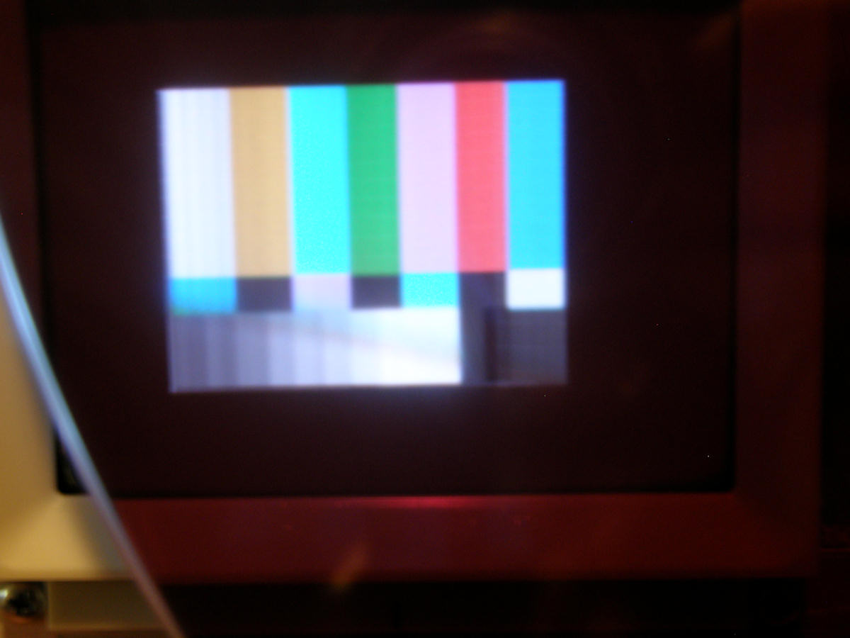
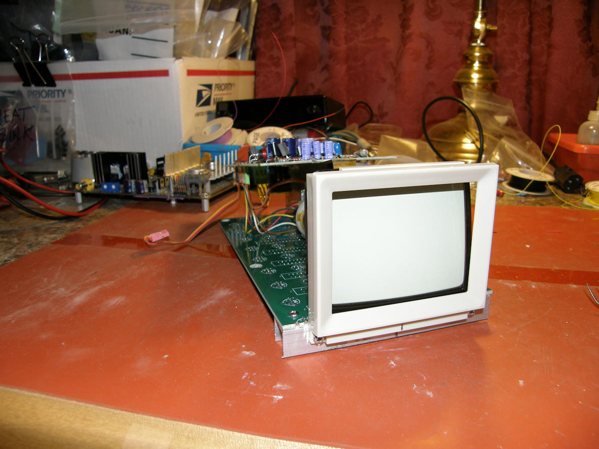
Goldmark 1 update. The video monitor achieved first light this week and there are now two YouTube videos showing it in operation. [GOLDMARK 1 with servo and other issues, 4 minutes.] [GOLDMARK 1 operating very close to normal, 3 minutes.] There are few issues left to resolve. Balancing the color wheel is now number one priority and I will devote some time to this, this coming weekend. Then the monitor must be addressed. The CRT is out of focus and the scan raster is being modulated by the vibration of the near by very large DC motor. This blurs the image even more. At 80% the resolution of NTSC, we have no margins to lose here. Goldmark 1 works! We made our first color pictures today at 4:45pm PST. There is still a lot to fix. But the basic operation was finally demonstrated. First, the new video monitor is scanning well enough to produce a fine undersized picture. All of my new circuits worked virtually first time. Initially had the video signal inverted. That took only five minutes to fix. Adjusted the pulse width of horizontal drive and got the monitor to operate at its normal voltages. The scans were short in both axis as I expected. Horizontal needs an inductor changed to widen it. Vertical requires a capacitor change. I don't anticipate any problems there. The picture is currently scanning about two inches diagonal and nothing is pulling abnormal current or running hotter than normal. Then I put it all together for the first time. The video monitor, servo board and color wheel assembly. Turned it all on and proceeded toward success from there. It is making pictures. But, that does not mean it is finished. The servo is very slow to reach speed and it is sloppy when it is locked. It drifts in and out of phase constantly. I will balance the speed vs phase servo summing ratios to resolve this. [FIRST COLOR PICTURE FROM GOLDMARK 1] The darned thing was hard to photograph clearly because the wheel still needs to be balanced. The whole rig was trying to walk off of the table! Still, this is an excellent milestone. I will update the project article accordingly in a few days. I fixed the horizontal pulse timing and now have the entire picture on the screen. It was folded over previously. Now I can set the drive pulse width to where the flyback and yoke are working perfectly and also have full image centering control now. [Retimed horizontal pulse, proper color bars now] Goldmark 1 project update. Completed the mounting of video monitor number two. It was made by Sony for Tektronix in the mid 1980s. The Akai CRT is on the side lines for now. We will be testing this 3.5" CRT monitor pulled out of an obsolete logic analyzer. It requires plus and minus five volts. So, I added two new voltage regulators and heat sink to the servo board just for this purpose. We will need to add an inverting video amplifier with some unknown amount of gain. I have three spare video op amps on board for just such an emergency. Next step is to measure and make two interconnect cables for between the video monitor and the main servo board. Then add the approriate connectors and new sync and video circuits to the servo board. I feel some trepidation about getting this new CRT monitor to work at 29.16KHz. It was running at near 15.75KHz in the analyzer. I have the full service manual and monitor schematics. So that helps. But, who knows? It just might work. Goldmark 1 project update. I have obtained another CRT video monitor to try in this TV. It is an instrument monitor rmoved from a logic analyzer. I fear it will also be a dud in the end because it turns out to be a Sony tummy TV. But the ciruits are stripped to the bare minimum. This might mean that bending the horizontal scan rate won't be as difficult as with the Akai monitor. Fingers crossed there. I started the day by adding the new plus and minus five volt regulators to the color wheel servo board. The new monitor use this for its primary power supply. Simple enough. Mounted a large solid heat sink for the regulators and had it all wired before lunch time. Have been slowly assembling the monitor support frame. I have created the base platform to fit where the Akai monitor previsouly did. Mounted the CRT bezel to some C channel extrusion and bonded that to the front of the base. Tomorrow, a trip to the harware store for three inch spacers to hold up the circuit board and to completely mount the CRT. Then it will be safe to power up. Please stand by. [Sneak peek 1] [Sneak peek 2]Happy New Year! Added an update status report to the bottom of [Goldmark 1, part 7] page. It details the latest progress in designing a horizontal magnetic scan circuit for the three inch field sequential color TV project. To see years 2007 to 2013 What's New pages, [CLICK HERE]. Scroll to the bottom of each year to find a link to the previous year. [HOME] Created: April 6, 2012, Last updated: April 02, 2014 |