|
LabGuy's World: 'Tiny Ike' - Iconoscope TV Camera Project
PART SIX - DEBUGGING. Can Tiny Ike finally see? 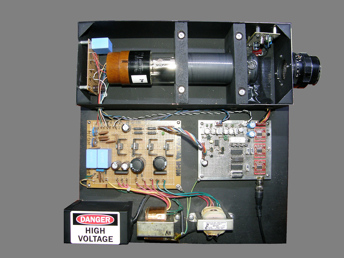
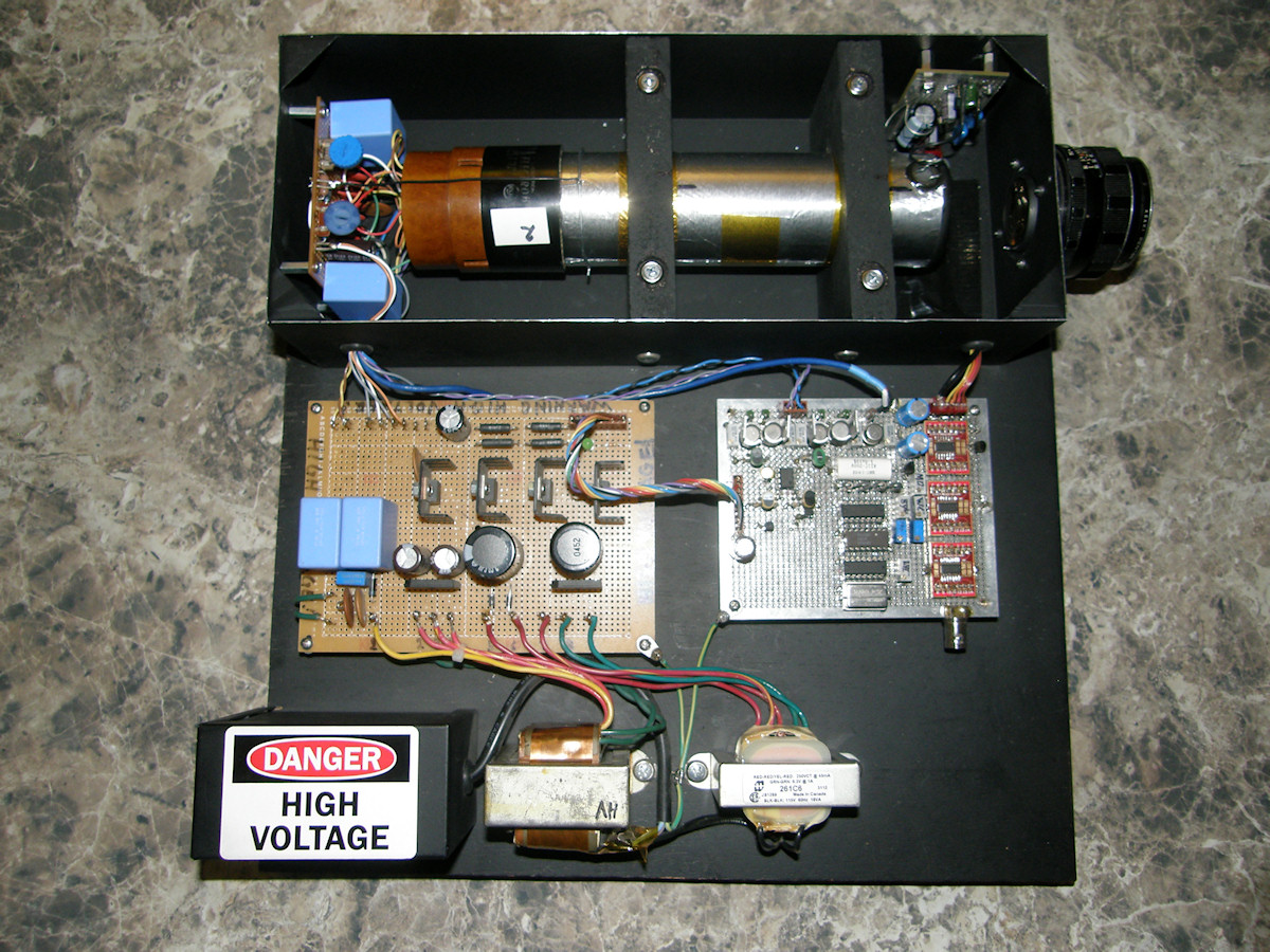
Completed Iconoscope Camera - 20170313 Here is the whole thing for all to see. The project has reached the point where complete testing could begin. Results are both promising and astounding. The scan circuits are working beyond my expectation. Blanking driver is working. Video preamp is working. Let's see the first recognizable video output from Tiny Ike, that occured on March 12, 2017. 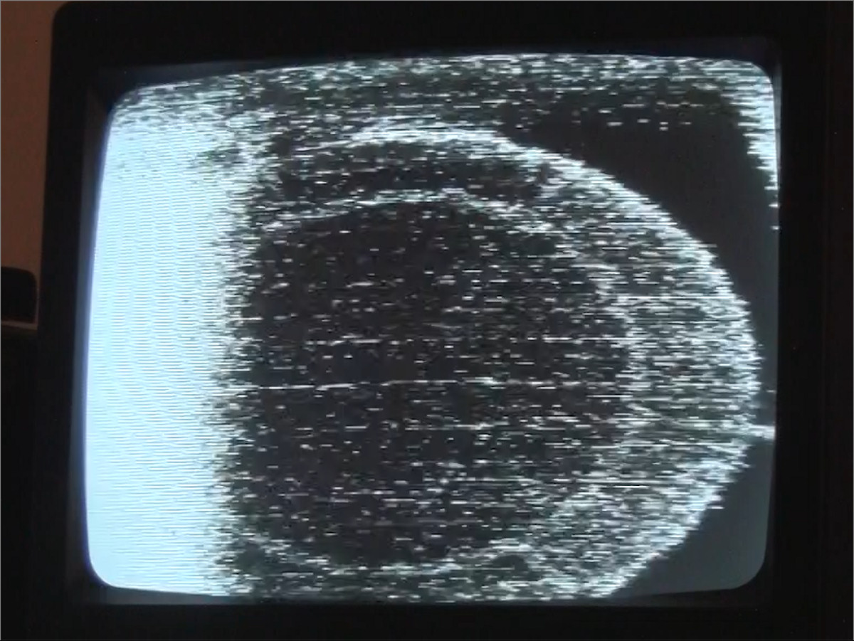

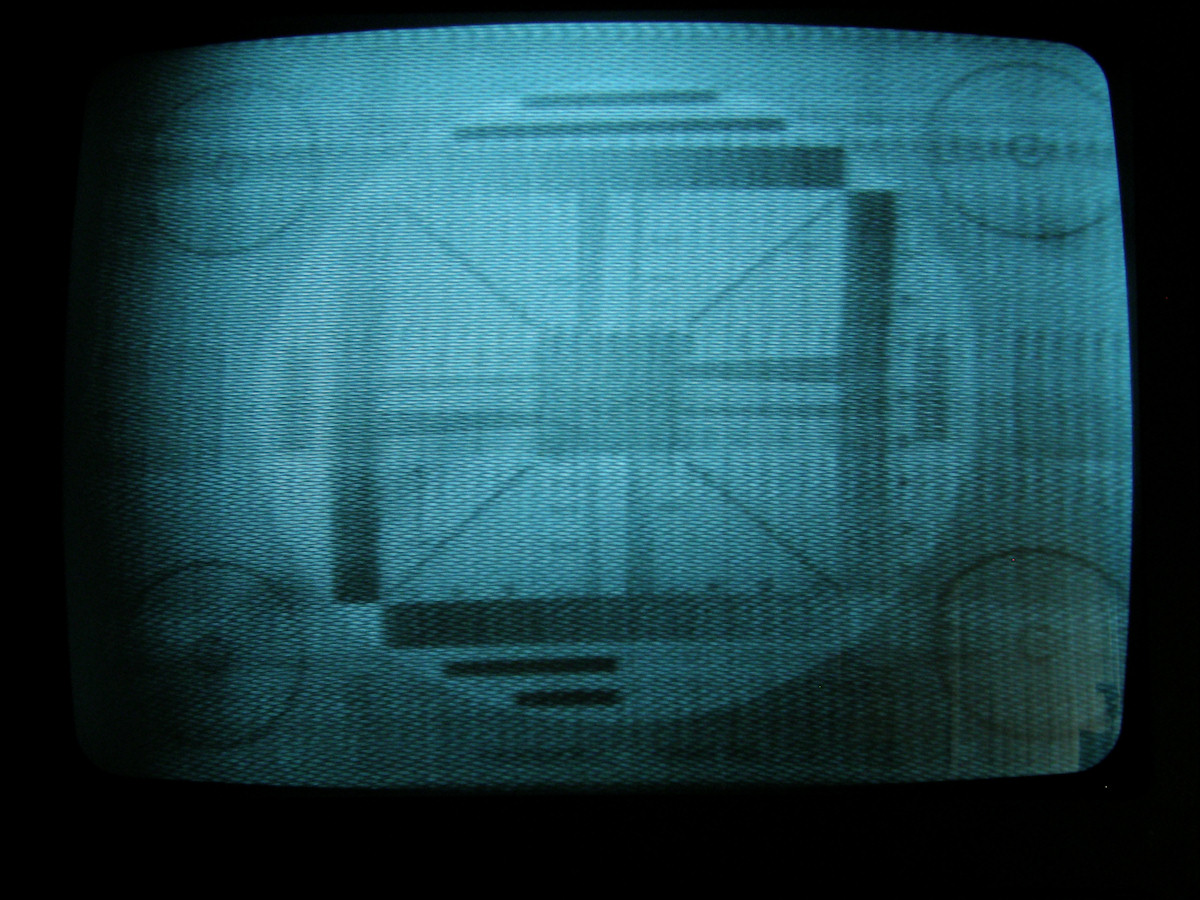
First Recognizable Images - 20170312 The first image that we saw was the mosaic support frame inside the tube. All this time, I had been supplying far too much deflection voltage which resulted in enormous overscan. The first time I noticed the circle it was about the size of fruit loop in the lower right corner of the monitor! After adjusting the scan size controls down, the first picture was seen. Probing and adjusting the video amplifiers and checking the electron gun voltages turned up several new problems. The beam control did not have enough range toward cutoff. All this time, the tube has actually had too much beam! I changed the BEAM control from a 50K pot to a 100K and readjusted the VSET for 800 volts between the cathode (K) and the second anode (A2) of the electron gun. Followed this with adjustment of the BLANKING AMPLITUDE control pot. This was adjusted until the visible retrace lines just faded away. The blanking circuit actually worked! I adjusted the gain of the video amps and readjusted the BEAM setting. We can now just make out the flash light in the second photo above. This is at the highest gain setting before the noise wipes out the image. I'm working on it...! Tiny Ike Project Video, Part 1, 4:00 - 20170312 A typical over reaction to the first sign of life in one of my projects. TROUBLE SHOOTING THE DESIGN: The signal to noise ratio of the preamp is like a children's fairy tale. Grim. Changed the iconscope mosaic load resistor from 100K to 1M ohm. RESULT: The preamp noise did not change. It remains intolerably high. 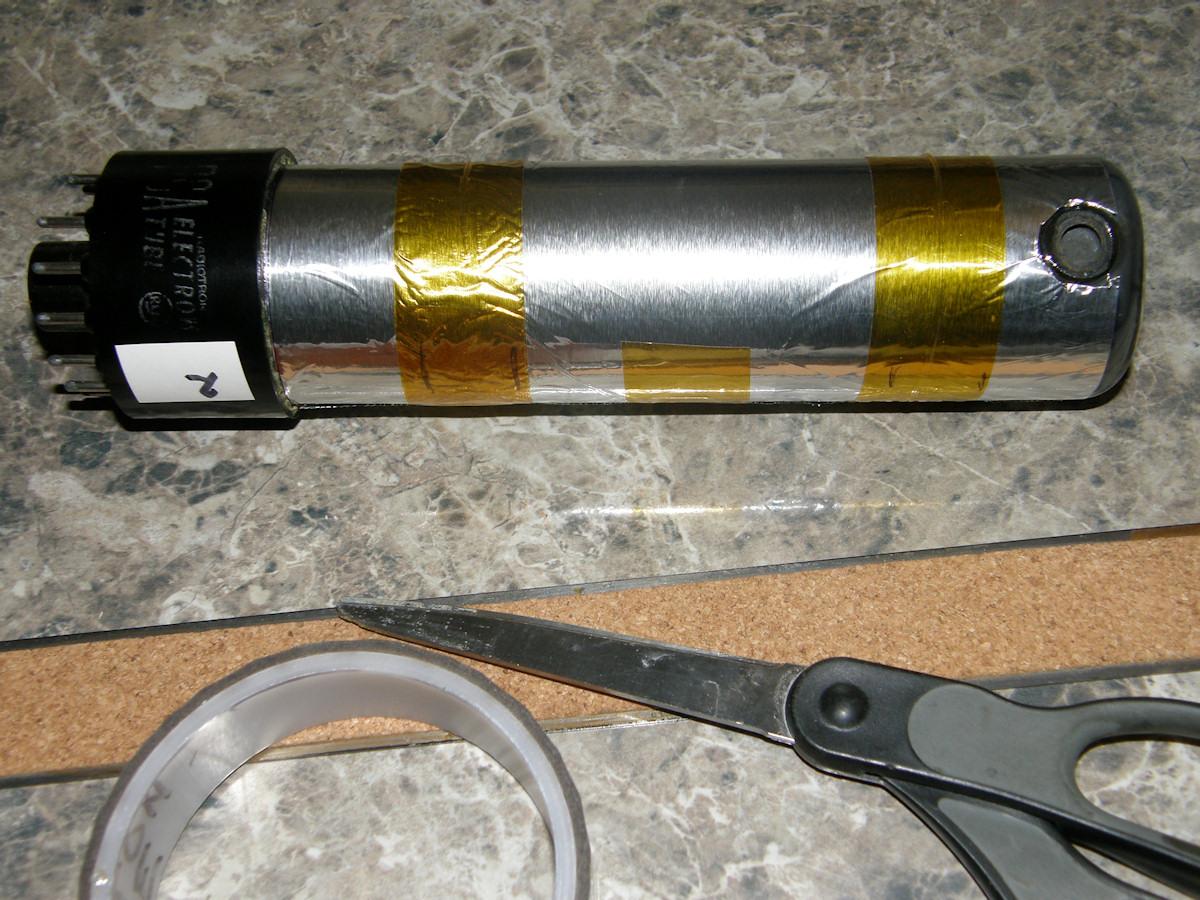
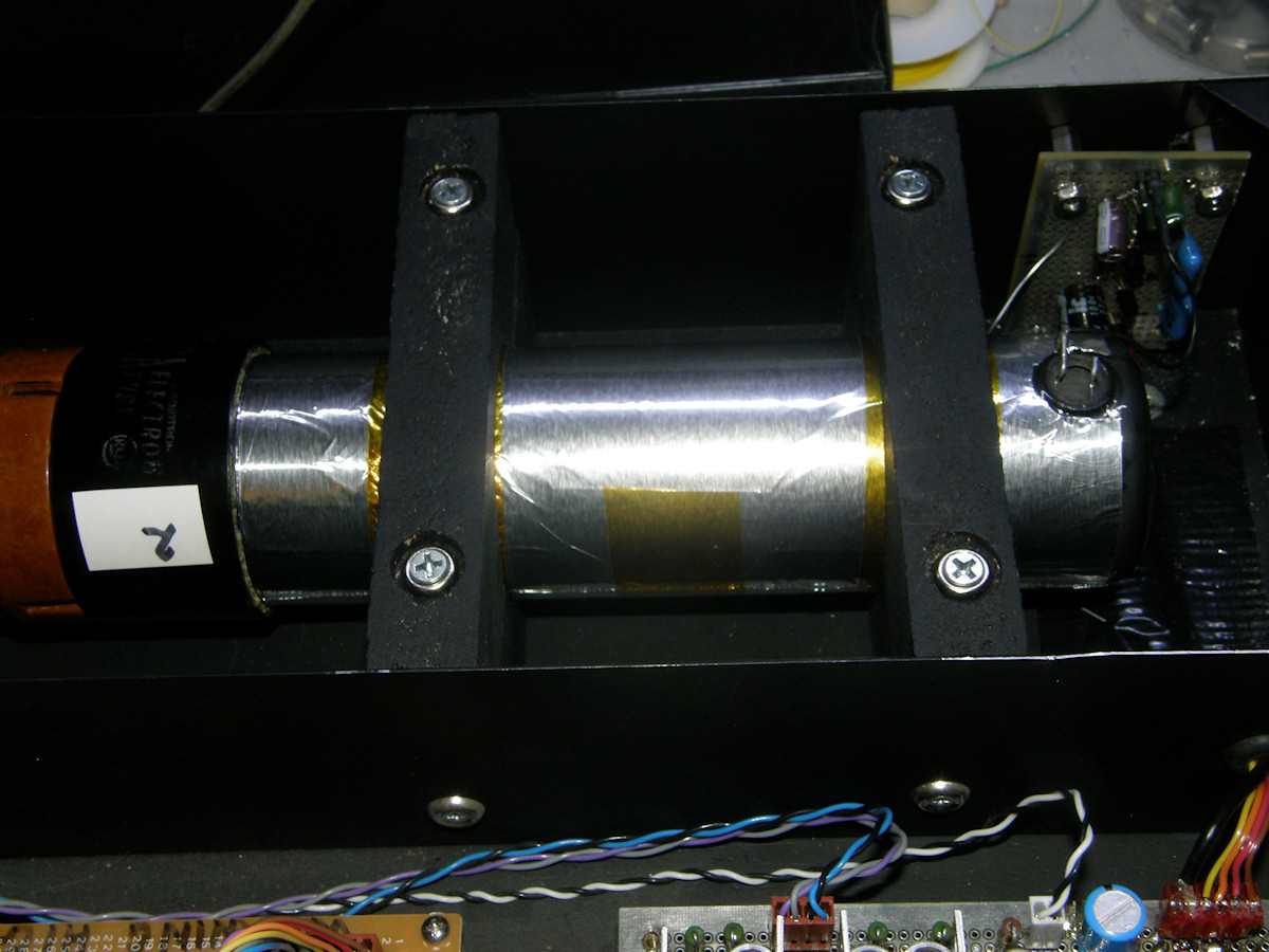
Shielding the 5527 with Aluminum Foil - 20170317 Let's try wrapping the iconoscope in a grounded metal shield. Some aluminum foil from the kitchen and kapton tape fits the bill nicely. First attempt is grounding the shield to the preamp. A bent heavy gauge paper clip is cinched down beneath one of the mounting nuts on the preamp vector board. It is bent shuch that spring tension presses it against the aluminum foil near the face of the tube. RESULT: This had no measurable effect on the preamp noise. It is still intolerably high. Discovered that the 0.47uF, 1KV capacitor that goes from the cathode (K) to ground had never been connected to the circuit. Doh! Its the blue capacitor visible on the relay board at the base of the tube. One wire was over looked. I installed the wire and now the capacitor is positively wired into the circuit. Checked for any other mistakes or oversights. None found. RESULT: This also had no measurable effect on the preamp noise. It is still intolerably high. Added a ground lead from the relay board to the aluminum foil. Tested with and without the preamp ground connected. RESULT: No change. Replaced the 2N3819 FET in the preamp. RESULT: SUCCESS! The high frequency noise is GONE! Replaced by a hideous amount of AC hum. That's progress for you! 
The Finally Working Preamp - 20170322 After replacing the 2N3819, the preamp was free of HF noise. But, now it suffered a strong 60Hz AC hum. This was repaired by placing the 10uF, 450 volt capacitor on the MOSAIC BIAS line, pin 1 in the main connector. This knocked all traces of hum from the preamp output when BEAM was blanked. But, there was still hum in the output video when the BEAM control was turned up, indicating a new problem in the electron gun bias circuit. Tiny Ike Project Video, Part 2, 5:30 - 20170327 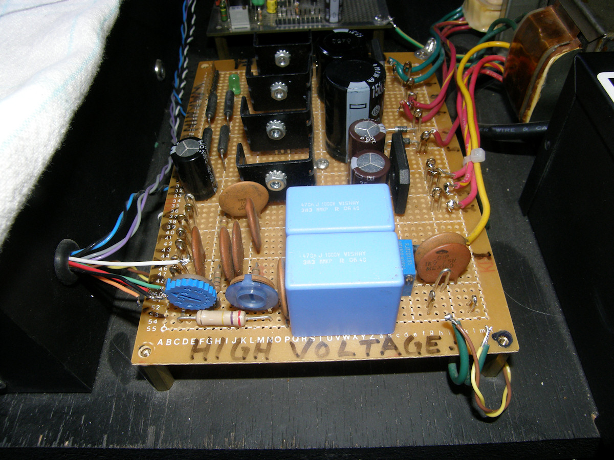
Start of the Major Rebuild - 20170323 Sometimes the obvious is not so obvious. To me. These unshielded bias circuits, to the left of the two big blue capacitors, make a spiffy antenna. Noise was being coupled through to the electron gun then to the mosaic. 60 cycle hum was so bad, half of the screen was blacked out. The circuitry has to to come off of the unshielded board and move inside the aluminum box at the base of the tube. What a rooky mistake. Ha-rumph! Moving right along... 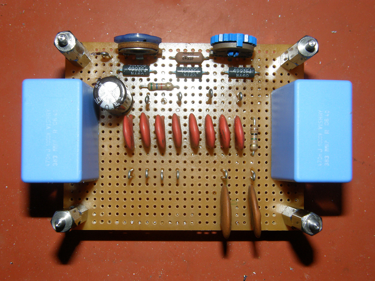
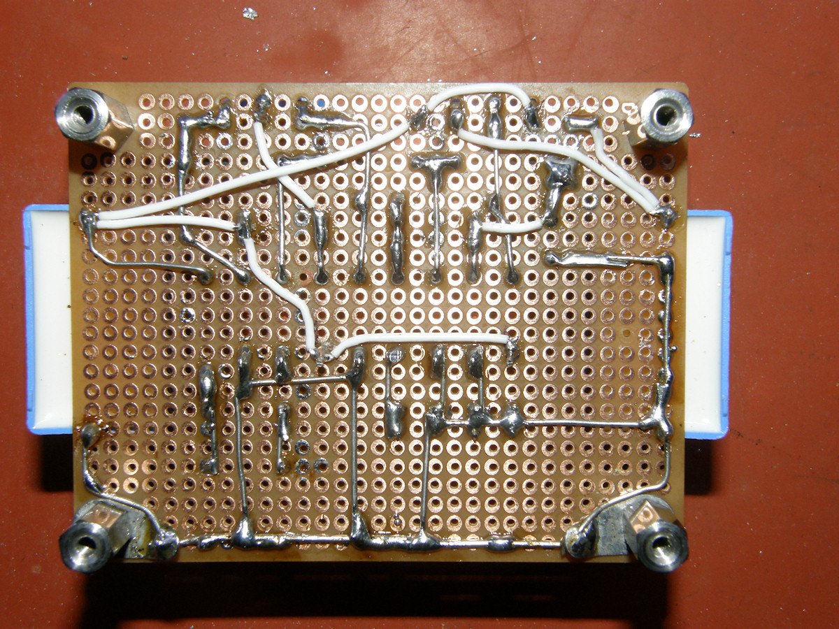
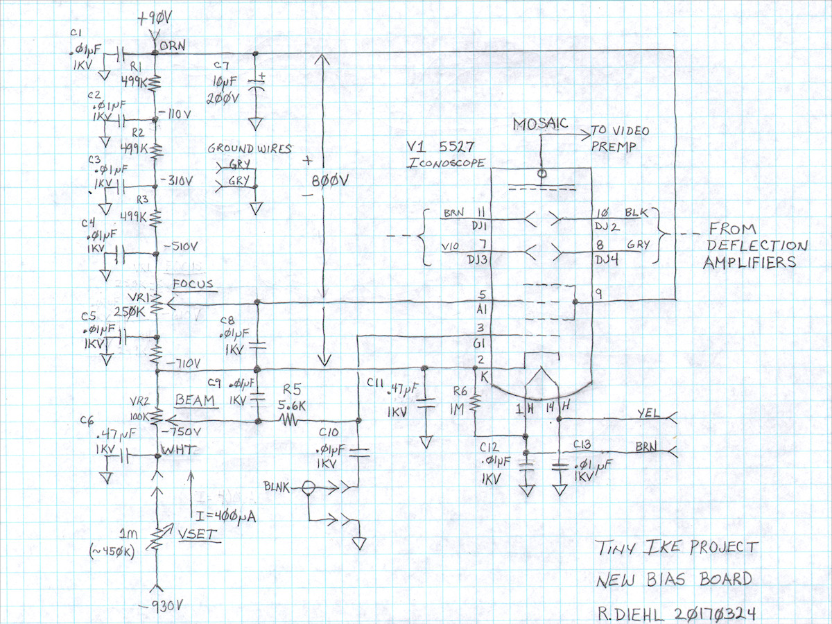

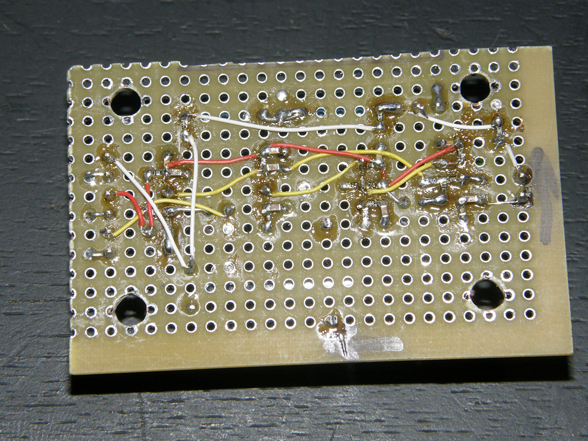
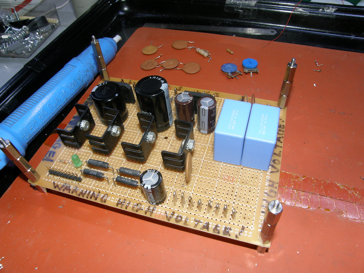
The NEW Electron Gun Bias Board - 20170323 Way more better! On the top edge of the board are located the BEAM and FOCUS pots. The voltage divider resistors are located just beneath them. All resistors, including the two pots, are 1/4W. In this project, anywhere you see a white wire interconnect on the circuit board, that is an indication that it carries high voltage. The other wires have a color code too. The color of the wire denotes the 5527 pin number. Brown for 1, red for 2, 10 is black and 11 is white again etc. Its not perfect. But, it makes connecting the wires much less error prone. Wires that enter and exit the board are called fly leads. The two large blue capacitors are the .47uF, 1KV units. One for the -750V power line bypass and the other is the cathode (K) bypass. The electrolytic capacitor is the 10uF, 200V bypass of the +90V. The row of eight orange caps in the center are the voltage divider bypass capacitors. The two tan colored capacitors, bottom right, are the HF bypass for the heater leads. All connections are via wire loops that all of the fly leads attach to. The four wire loops visible just below the resistors in the first photo are the electron gun connections in this order: A2, G1, A1 and K. The two loops at the top of the caps in the lower right are for the heater fly leads. Just to the left is the blanking input and three ground points. +90V and -750V loops are at the very upper left, +90V loop being hidden by the 10uF cap. The last two photos are the schematic and physical layout sketch of the new bias board, plus addtional system notes. Tiny Ike Project Video, Part 3, 3:00 - 20170327 
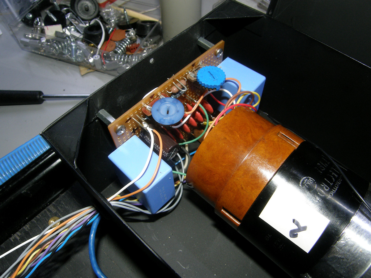

Before and After, New DC Wiring - 20170323 The completed new bias board board fits into the space behind the iconscope tube connector. Two holes were drilled in the cover of the box to allow convenient screw driver access to the BEAM and FOCUS pots. The leads from the divider resistors to the pins of the tube are now very short and are within the shielding of the box. 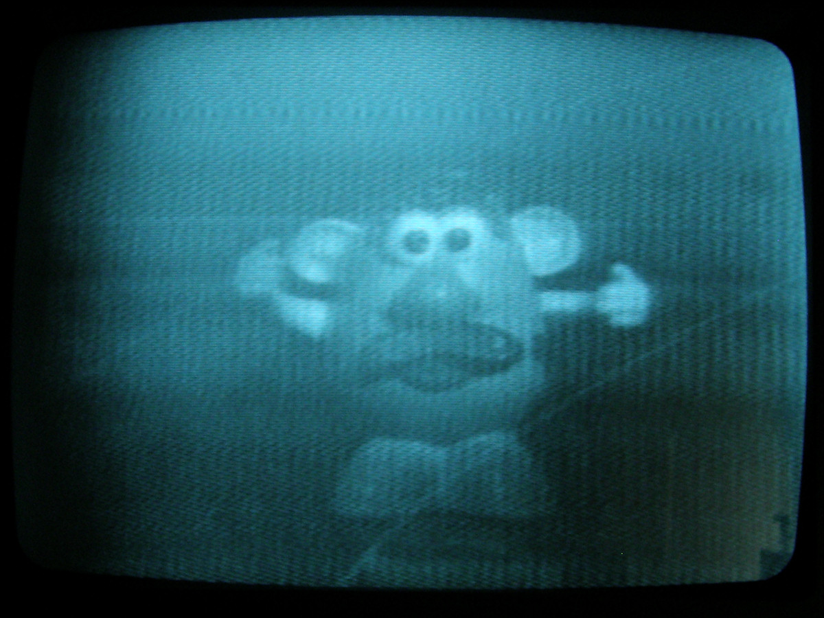
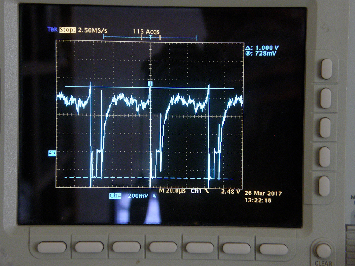
Finally Working! But it's a Glitch Fight! - 20170326 Tiny Ike is finally making reasonably framed images. For a while, we had 4/5 of a picture caused by a severe glitch in the active video. Still working on that. However, as you see, the camera now makes fairly noisy images. I'm still working on shielding everything. There is everything from CCFL noise to AM radio stations in the video as far as I can determine. Contrast is low, shading is heavy and there is still some AC hum to hunt down and exterminate. Tried to take some shots out the window today. No good. The brighter the light, the bigger the glitches! You can see the glitches in the waveform perfectly framing the blanking interval. More about that shortly. My stunt double, Spud, stands in for us, first photo. He is being lit with a large flashlight plus room ambient light. The test pattern, second photo, is from my Diamond Power light box and a standard resolution slide. The slide is lit with two 40 watt incandescent bulbs. This was how I received the unit. The light box is parked 19 inches (49cm) in front of the camera. The lens is an Asahi 50mm, f1.4 with a Leika lens mount. This is focused onto the mosaic which is scanned in a 4:3 raster. This comes out to 1.4" on the diagonal. Scanning is 525 line 2:1 interlaced NTSC without chroma. The last photo is of the video output waveform with blanking edge glitches. If I try to turn up the gain or boost the mosaic voltage, the glitches get very large and disrupt the TV monitor, causing the picture to undulate down the screen or just rip and tear. The video from the preamp also shows some form of "tilt" distortion. It is hooked down at the start of the line and hooked up at the end of the line. There are two possible causees for this. Either the blanking pulse coupling capacitors are too small or there is something wrong with DC clamping or BOTH. The clamp pulse is temprorarily HD. Turns out, the burst flag is not a good clamp pulse because it stops during the vertical interval. I think that was causing lots of picture bending at the top of the screen. Stay tuned as I hunt this demon and send it back from whence it came. The pictures are also a little soft as I intentionally rolled off the frequency response of the first video opamp after the clamp in an attempt to reduce some of the noise. Limited success so far. Will tune this to optimum or even remove it when the other circuits are working properly to spec. Tiny Ike Project Video, Part 4, 4:00 - 20170327 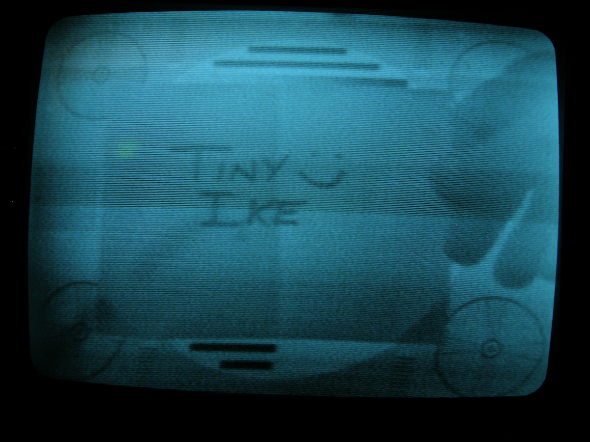

A Few More Photos - 20170327 I put an out of date photo of the Tiny Ike in the last video. So, here are a couple of the better screen shots and the latest version of the Tiny Ike. I changed the frequency rolloff capacitor from 100pF to 47pF to increase sharpness a little. The pictures are starting to look good now. Yet there is still room for many improvements. Tiny Ike Project Video, Part 5, 9:00 - 20170328 Allow me shed some light on the subject that you may become illuminated. 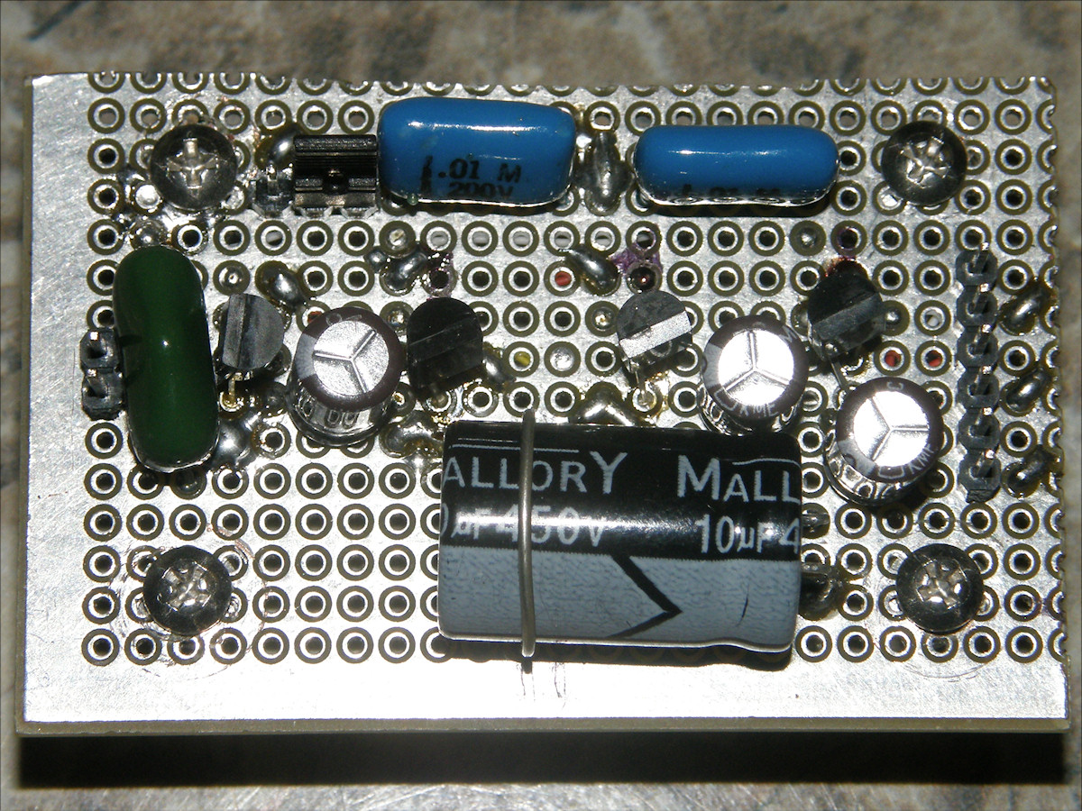
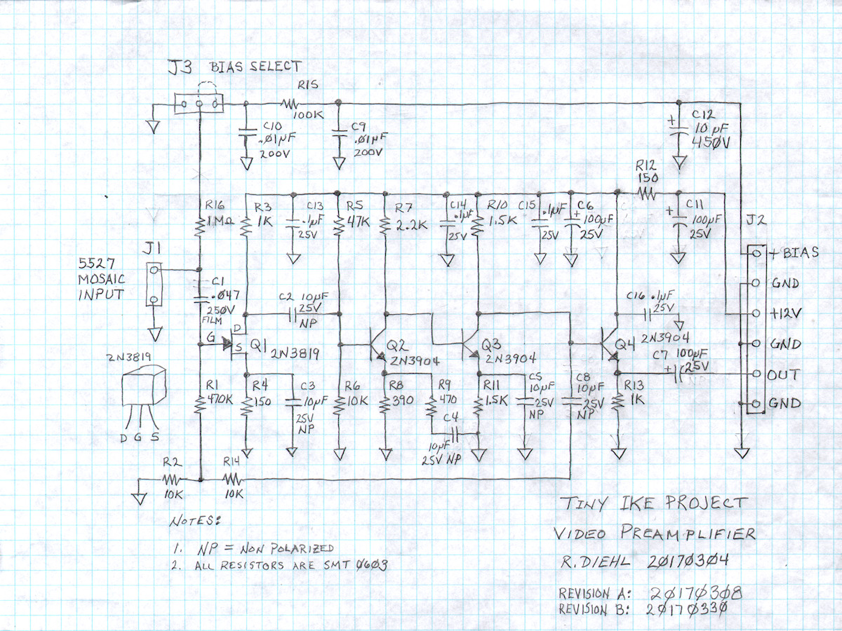
More Preamp Improvements - 20170330 Let us catch up on the state of the preamp. Ninety nine percent of my experimentation does not get documented. Mainly because so many of the experiments are duds! So, let's look at all of the changes just to the video preamplifier since it was last mentioned, eight days ago. I've been a busy little beaver. While fighting the noise problems I added a 0.1uF ceramic capacitor (C13 - C16) to the top of the collector load resistor for each of the four stages. I then added the two 100uF, 25 volt electrolytic caps (C6, C11) to the +12V power line. After replacing the FET (2N3819, Q1), I also added the 10uF 450V cap (C12) to the +BIAS line. After making changes to that BIAS control circuit on the main board, the original .047uF, 100 volt rated capacitor (C1) was not voltage rated high enough. It was changed to a .047uF, 250V model. Both are mylar film capacitors. It is the green one right next to the mosaic input pin. Next step was the installation of jumper jack (J3) to allow for selecting either a variable biased mosaic or a mosaic referenced to signal ground. In tackling the strange parabolic distortion of the preamp output, I increaed the size of the ouput coupling capacitor (C7) from 10uF to 100uF. The original 10uF ceramic cap is still in parallel with the electrolytic. This had no effect on the parabolic distortion. My suspicions lead me to the blanking circuit and the lack of a proper clamp pulses. That concludes a week's worth of changes just in the preamp alone. 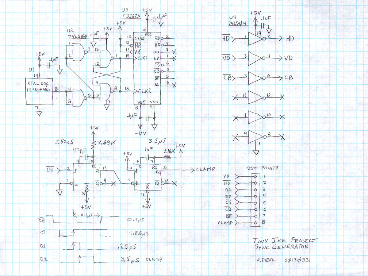
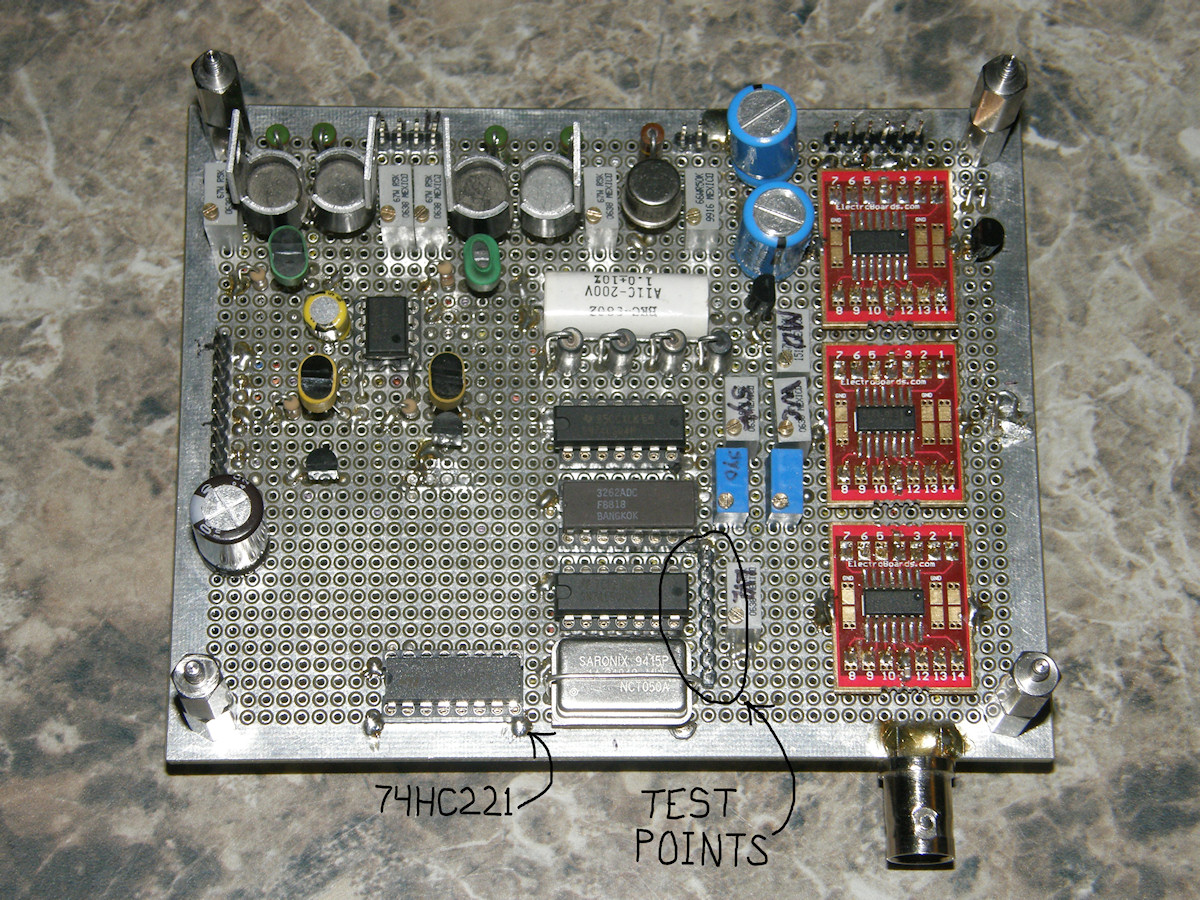

Clamp Pulse Circuit Improvements - 20170331 There are two areas of trouble in the DC restoration process. The big problem is that the electron beam blanking circuit is not working correctly yet. It needs to be adjusted with scene changes. Even without automatic circuits, this is wrong. Since this requires rework on the high voltage bias board, we will save that for later. I have decided to address the second problem first. Second problem. The F3262A sync generator IC does not directly produce a viable DC clamp pulse. Have added a 74HC221, dual non-retriggerable one-shot. It produces a very high quality clamp pulse based on the rising edges of composite sync. The first stage sets a 250nS delay before triggering the second stage for three point five microseconds. This is the middle of the horizontal back porch interval. In the vertical interval, this pulse will also clamp correctly in the presence of serration pulses and equalization pulses. This will clamp an AC coupled composite video signal's vertical interval flat as a plank. This circuit is used here because the glitches caused in the video by the clamp FET will occur completely inside composite blanking period. Because the video gate is open during active blanking, the clamping glitches will not appear in the output video. These glitches are caused when the clamp FET switches off and on. See: DC Restoration Circuit, at the input of the video output processor. Also added, during today's sync system upgrade, a 1x8 strip of header pins providing 8 test points for all the primary pulses in the sync generator. These are as follows: HD, VD, OD, EV, CS, CB, BF and CLAMP .

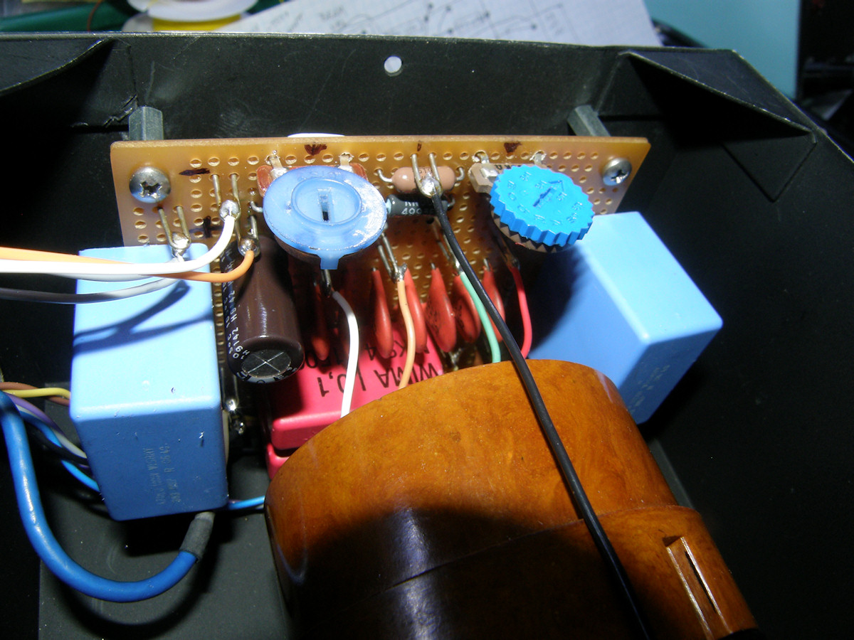
Larger Capacitors For Beam Blanking - 20170401 Referring to the schematic in the first photo. Capacitors C9 and C10 are rated .01uF. The original, all vacuum tube, design that I copied had called out these two capacitors as .1uF. I only had .01 values when I originally built the bias board. Two new .1uF, 1.5KV capacitors have been installed in parallel with the original C9 and C10. Those are the two big red monsters on the bottom edge of the board. This now gives us .11uF for each cap. This improved the coupling of the blanking pulse to the control grid (G1). The new capacitors do require much more space. But, we managed to successfully squeeze them in. Some of the wire loops were relocated because the huge caps crowded them out. The wires going to the 5527 were shortened again to eliminate the rats nest look behind the tube. If it looks bad, it probably is. After all that, the camera operates exactly as before, as far as I can tell. At this time, I will declare that the Tiny Ike is functionally complete. This is a completed project for all practical purposes. Over time, I will more than likely work on it and make various improvements. Those changes will be reported here if/when they occur. Will be closing this project now so I can move on to my next exciting project, "The Chief". Stay tuned! Tiny Ike Project Video, Part 5, 1:15 - 20170401 Tiny Ike is completed. [HOME] [ELECTRONICS PROJECTS] [TINY IKE INDEX] [PART 7] |