Between 1984 and 1987, I scrounged all of he the parts necessary to build a black & white frame grabber. In it's first incarnation, the frame grabber was connected to an S-100/CPM computer system. In 1986, it successfully captured it's first digital video image, received from a television tuner, and stored it to an 8 inch floppy disk! In fact it was this picture, right here:
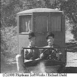
Laurel & Hardy in the film, "Them thar' hills" (The following discussion is somewhat technical) During the course of the frame grabber project, I learned about video speed A/D's & D/A's, sync separators, black level clamps, white clippers, HF phased locked loops, voltage controlled RF oscillators and enough other jargon to write a pretty narly sci-fi book. But I didn't. Instead, I continued to add circuitry, one block at a time, until I had a complete, stand alone, digital video subsystem. The hand wired circuit boards looked like this: 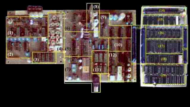
Frame Grabber Original hand built circuit baords (The text in the picture is impossible to read, so I re-list it here for your convenience)
TECHNICAL SPECIFICATIONS: . Resolution: 207 pixels x 240 lines at 8 bits / 256 shades per pixel. . Memory: 65,536 x 1 Byte @ 120 nS . Sampling rate: A/D: (NTSC) 4xS.C. 14.318 Mhz . Memory: (NTSC) Subcarrier 3.579545 Mhz. . Host Interface: Two 8 bit I/O ports: Port 00h: Data I/O port. Port 01h: Command / Status port. . Now, anyone who knows video spec's is probably nauseated by now. This is probably the worst possible combination of spec's around. (I told you, I scrounged the parts for this project.) Subcarrier rate sampling couldn't be worse! The aspect ratio (width x height) of the samples was a disaster! The memory wasn't large enough or fast enough to go to another frequency, even if I could. The sampling rate was trapped by the Fairchild 3262A TV sync generator chip that I had used. Even though I call it a Frame Grabber it's really a Field Grabber. . THE STORY of Richard's Frame Grabber: . 1. The Codec: . Considering that in 1984, the cost of the A/D converter chip was around $125.00, I wasn't going to be able to buy one. I had just purchased a house and was tapped out. I was working at Sony then as a "super tech" testing BVE-3000 video edit controllers. One day, I happened to mention this new A/D chip within hearing range of a fellow named "Senzo". Little did I know, but Senzo had worked for the guy that designed this new A/D chip. Within a day or two, I was handed a package of 3 brand spanking new: SONY 20052A & A1008's video speed A/D converters and matching sample & hold chips! That gift was worth over $1,000.00 and I knew it! Senzo, my bestest friend in the whole wide world, had relayed my enthusiasm to the right people and obtained those chips as gift for me. What a bunch of nice guys! . 2. The summer of the VCO: . By the summer of 1985, I had enough parts to consider assembly of the codec portion of the project. This entailed an analog front end with sync separator and D.C. clamp, sampling clock phased lock loop and the A/D & D/A converters proper. At this point, I realize that I have no idea how to build a high frequency, high stability, phased locked loop. The text of the time, on the subject, talked about subcarrier locked clocks. This allows the designer to incorporate chroma processing functions with relative ease, but devastates the height to width ratio of the frame buffer. (More on that later) . The center of a phased locked loop is the voltage controlled oscillator. Having decided on four times subcarrier as my sampling frequency, I then had to figure out how to build a 14.31818 Mhz VCO. Today, this is trivial, then it was NASA grade complexity! You have to find a transistor with enough gain to sustain oscillation, choose appropriate capacitors and inductors, filter the power supply lines to prevent modulating the VCO with line noise, etc.! I built the PLL circuit with a socket where the VCO was supposed to go. This allowed me to build multiple VCO's and test them until I got it right. . I built 11 VCO's that summer! I tried LC oscillators, Collpits and Hartley became my friends. I tried crystal oscillators, new wave people became my friends... I dreamed VCO's and PLL's! It even gave me nightmares! I talked about the circuits with anyone who would listen, many people tried to discourage me, saying that it would never work. I ignored them. I got help from many people who never gave up on me. By September I had a phased locked loop that would lock up to VCR playback (jittery) after it had been received from my 200 mW homemade TV transmitter on channel 3 (noisy). It was worth every bit of effort. . To those of you, out there, who are struggling with some sort of technical problem, keep struggling and ignore the nay sayers. For they are dense and full of shhhhh.... You get the picture! (pun intended!) . 3. Finally! A big enough memory module! . Up to this point, I could digitize video, but could not store it. In that era, memory speed was around 150 nS for ultra fast rams. At 14.31818 Mhz, I would need memory that was at least 70 nS or faster. One day, a friend of mine who worked in a stock room, was cleaning up (so he says) and found a memory SIMM module. He knew all about my "frame grabber", as did anyone who knew me, and gave this gem to me. I sent him back for the data sheets. The next day he brought them. NOTE: Make sure the data sheet is for the part you are holding in your hand! Not paying attention, due to orgasmic excitement, I believed that I had a 256K / 100 nS memory module. I guessed that I could push the memory speed to 70 nS as I didn't need absolute data integrity like a computer would. At worst, I expected to see sparkles in the image and would fix that by replacing the ram module when a 70 nS one became available. So built the circuits to support it on a new PCB and plugged it into the codec board with a short jumper cable. . The day came when it was done, so I turned it on. To my horror, I stared at venetian blinds on the monitor. 32 lines of video followed by 96 lines of black repeated down the screen. Scratching my head, I started reading the memory data sheet, probing the address lines on the module, etc. Nothing there. All drive signals present and accounted for. . So I probed again. That's when I noticed that there was no traces hooked to address pins 16 & 17! Looking closer, I discovered that the memory module I had been given, was only 64K! I fainted. . 4. But, why isn't it color?: . The only answer to fix it, was to lower the sampling frequency by the same amount. So divided the sample clock by 4 and got 3.579545 Mhz! Color subcarrier, the absolute worst sampling frequency on earth. Color operation was now impossible. To do color, Mr. Nyquist determined that you have to sample the signal at least twice as fast as the fast part of the signal. Boy, was I bummed for about 5 minutes. Once I had a full screen image, it was time to add a computer interface. . 5. How do I save the pictures to disk? . I pondered the issue of connecting the frame grabber to my computer. The computer I had then was a beauty, too! Z80 based, 4 Mhz, 64K of memory, dual 8 inch 1.2 MB floppies, and my new 5 MB hard drive! Frame grabber pictures were 64K, so theoretically, I could save 18 pictures on a single floppy disk or almost 100 of them on the hard drive! Realize that this is fantastic specs for 1986! . My interface was based on two I/O ports. One for the data, the other for commands and status. By doing it this way, I would be able to migrate the frame grabber to each new computer that I knew I would eventually get. The interface worked flawlessly. . The first program was written in MS basic. I was not able to save the image data perfectly with that program, because documentation of the day failed to mention the binary file modes. Basic was horribly text oriented. So, to compensate, I had to filter all of the bad binary codes in the video, pushing them to the nearest "safe" text value possible. This worked like shhhhh..... . So, next I switched to assembly language. I had never written file operators in assembly so I experimented. Crashed the hard drive, where by the way, all of the source code was located. No backups of course.... . Starting over I worked from the floppies from then on. Finally, having grabbed the Laurel & Hardy image from the local PBS affiliate, I successfully saved it to floppy and was able to reload it to the buffer! Immediately, I made a dozen copies of that image because I knew that was HISTORY! . 6. Conclusion: . From then on, I hooked the frame grabber to half a dozen different computers and even loaned it to a friend of mine for two years. It was one of the most rewarding experiences in electronics that I ever had. I learned a voracious amount from it. I laughed, I cried, I cursed! This simple, in hindsight, project made me a better engineer than all the books or lectures combined. To those of you who would consider an impossible project like this, go get 'em! - - - rnd 12/13/97 [HOME]......[EXTINCT DOCUMENTATION] Last updated: January 09, 2005 |