|
LabGuy's World: NBTV - 32 Line Televisor Color Conversion - Part 1
[HOME] [ELECTRONICS PROJECTS] [PART 2] What would Rowan and Martin's Laugh In look like on a 1929 mechanical color television set? Let's find out! 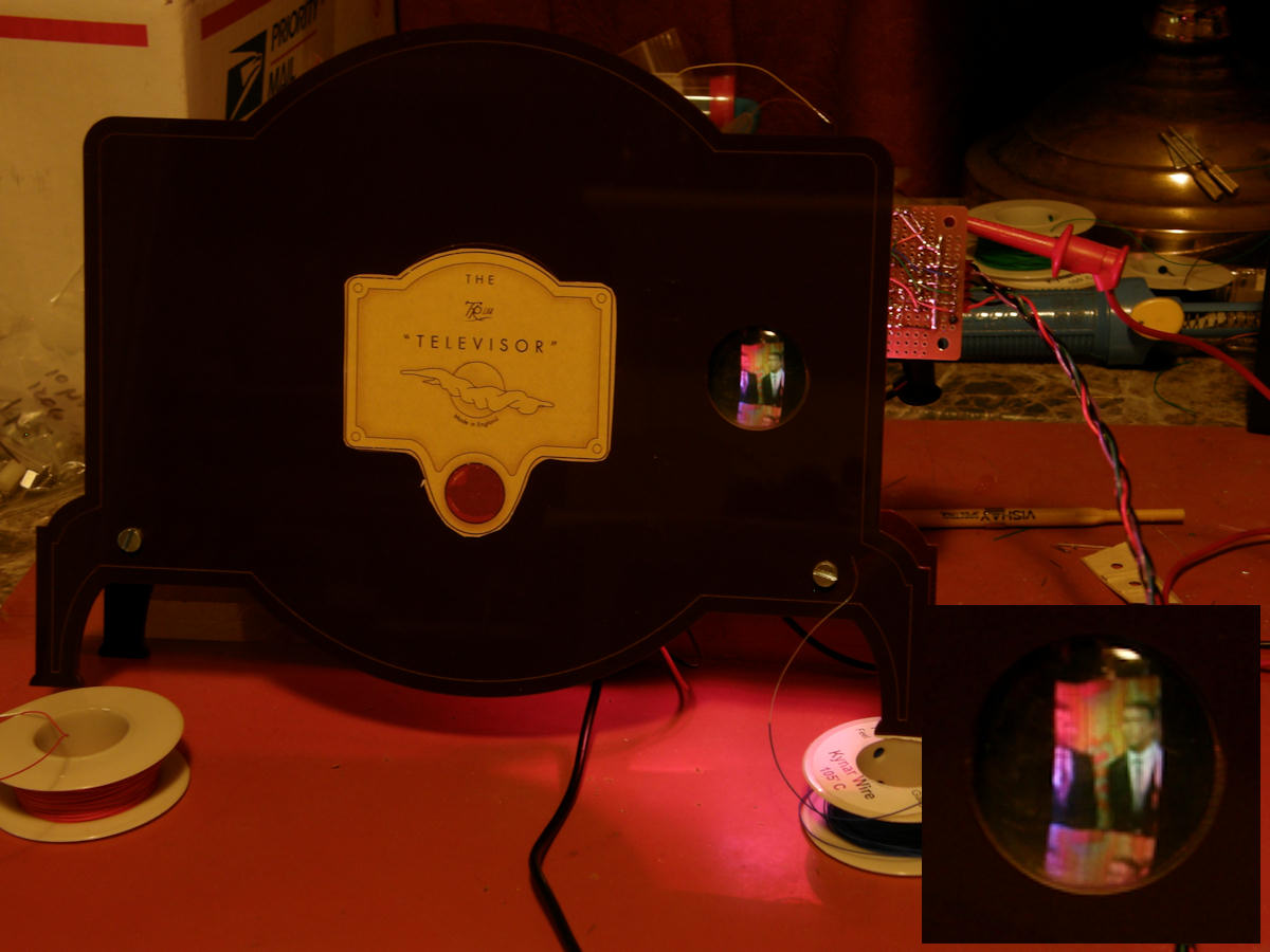
Labguy's NBTV Baird Televisor replica doing its thing in COLOR! By 1929, [John Logie Baird] was transmitting moving images across his lab and across Britain and the world. Not bad for high school drop out. Reminds me of a labguy I know somewhere... But, I digress. Baird applied the Nipkow (nip-cough) scanner disc, along with selenium photo cells and neon lamps to produce remarkable pictures with bare minimilist technology. You might say that Baird was attempting to recreate a mnemonic memory using only stone knives and bear skins! The image consists of 32 lines, scanned vertically from bottom to top, right to left. At only 12.5 frames per second. This is not much more resolution than an icon on your computer desk top! But, with more colors! It flicker like the dickens too. Be amazed. I insist. Learn more about the Narrow Band Television Association at their [website here]. Mechanical TVs, tools, medthods and plenty of great example projects. 
You want a Televisor. Don't you? Admit it. It's true. Here's your chance! Click either image above to visit the Mindsets web site. Design, technology, science, art, gifts and much more. Once there, use their search window and type in Televisor. Mindsets is in the United Kingdom and has many kits and parts for the science experimenter. It is a great resource for all the European friends of Labguy's World. Hi guys! The Televisor kit took me about 20 minutes to assemble. No soldering. All you need is a small straight blade screw driver. It comes with an audio CD containing 25 minutes of images and sound. You play one channel to the Televisor. The other channel to your amp and speaker. Easy. About a hundred bucks. Cheap! 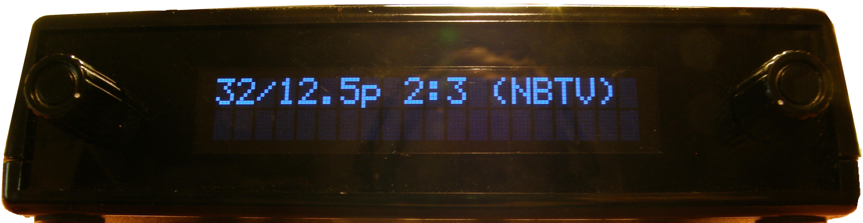
Labguy. From where do you get those spiffy 32 line RGB video signals? I'm glad I asked! They come from the [Aurora Design World Converter] Model WC-01, of course! Read the [World Converter User Manual] for yourself to see what a powerful tool this is for the person interested in all aspects of antique television. From restoration of authentic antiques or the construction of modern tech replicas, Aurora makes amazing products! They are Labguy approved for versatility, quality and value. Now back to the project! 
Labguy's NBTV Baird Televisor color LED driver circuit (This circuit is duplicated three times. One for each color of LED.) Could this be any simpler? The video is received into the 100 ohm pot and its parallel 300 ohm resistor. This forms a 75 ohm termination load for the video drivers in the World Converter. Next the wiper of the pot is connected to the + input of the op amp. The - input is connected to the emitter resistor of the 2N3904 general purpose NPN transistor. I designed it so that an input, at the op amp, of half a volt will produce a current of 100mA in the resistor labeled RISET. It is designed to pull the maximimum current through the LEDs when video is at 1 volt peak. In this case, .5 volts across RISET, produces 100mA of current. The op amp is trying to make the - input equal to the + input. It is as if the wiper on the pot were connected to the top of RISET. Without RISET loading the potentiometer in any way. Recall the transistor's emitter current equals approximately the collector current, as long is the beta of the transistor is 100 or better. So, this is a direct voltage to current translator. LEDS are current operated devices. Double the current and you double the brightness. Up to the LEDs natural limit of course. At some point, though current is increasing, every atom available that can make light is doing so. More power only means more heat until the device fails by melting. The driver circuit input voltage of 1 volt peak is scaled to a current of 100mA peak. The transfer of input voltage to equivelant light is nearly linear. The LEDs forward voltage drop is only relevant in that you must take care to have a high enough B+ to overcome the forward voltage drops of the LEDs. The more toward blue that LEDs go, the higher the junction voltage drop. The red LEDs have a foward drop of 1.9V each at 20mA, the green LEDs have a drop of 3.1V at 20mA, and the blue LEDs have 3.6V drop at 20mA. One other detail. The motor circuit is locked to the 32 line monchrome video output coming from the world converter. It spins at exactly 12.5 RPS or 750 RPM, locked to the video sync pulse. Separate red, green and blue video is sent independently to the light board. This makes for a total of four input signals to the colorized 32 line Televisor. Normally, the Televisor has its own one channel LED driver which gaves us the monochrome orange neon-like images. I removed the original single LED circuit board and replaced it with an assembly of my own design. The original board received the power through the two support posts. You will see that my board has the ground planes cut around the screw heads so as to not short out the monchrome LED driver. 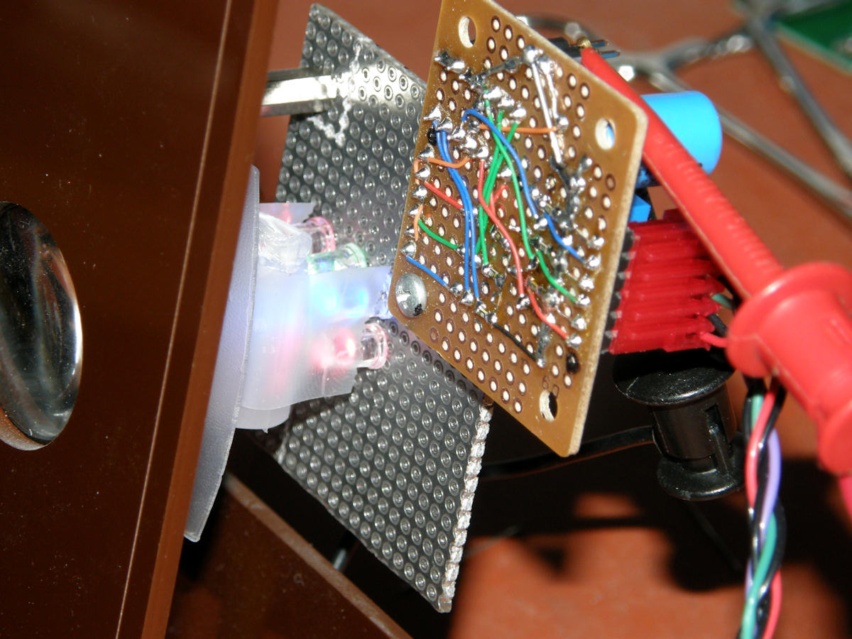
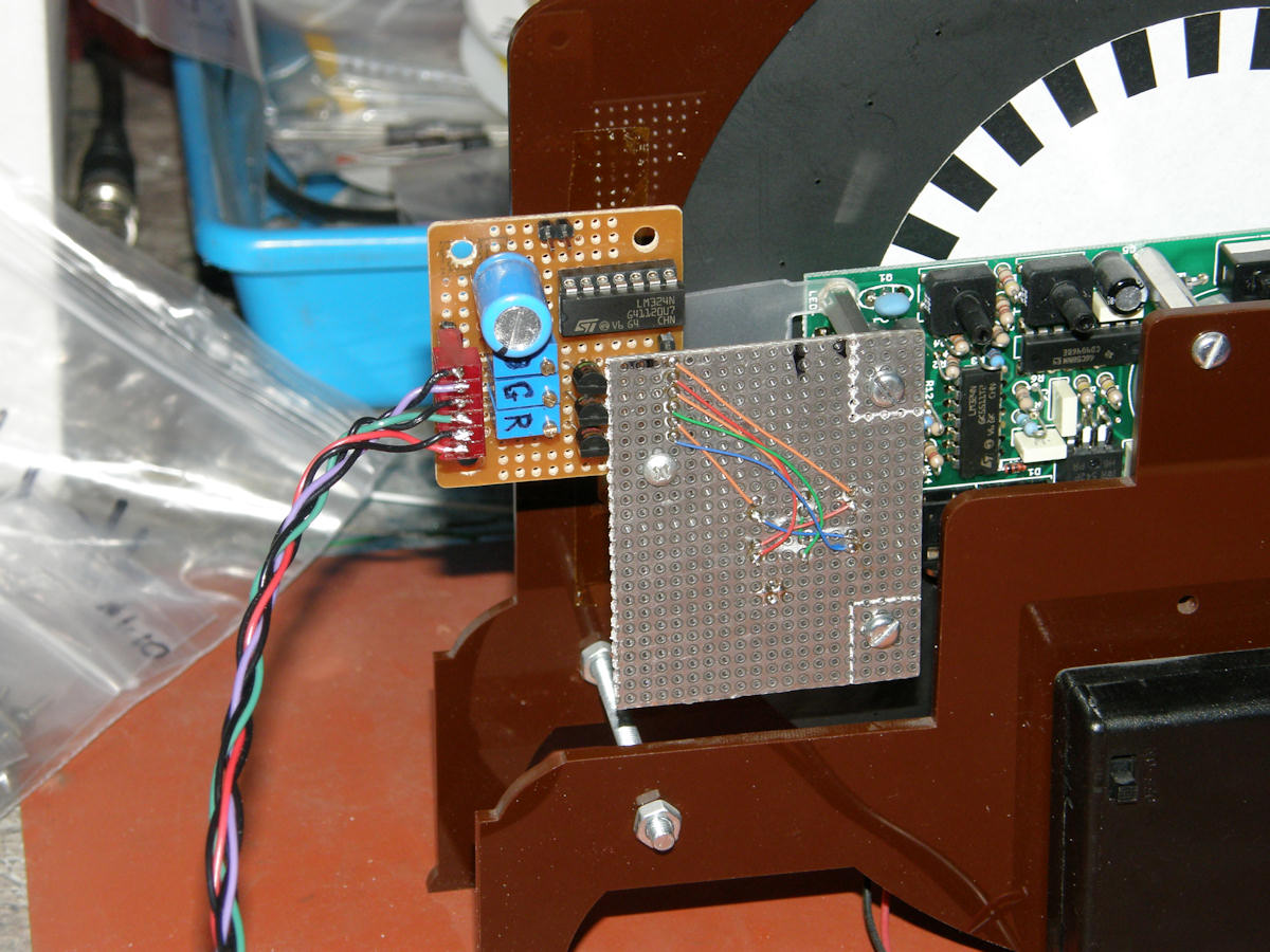
Labguy's NBTV Baird Televisor color LED driver assembly I chose some extra high brightness red, green and blue LEDs which I purchased from [Anchor Electronics]. These were rated at 15,000 mcd at 20mA current. I used two of each in each channel of the driver board. Video drive is delivered by the Aurora Design World Converter. It has video level RGB out puts (1Vp-p terminating in 75 ohms) for all of the mechanical TV standards. An optional programmable LED current driver board is available from [Aurora Design] for those who do not wish to do the soldering. The two stacked PCBs were not originally planned that way. I ran out of space on the first, smaller, board due to severely underestimating the space required. This happens in engineering all the time. The two boards are interconnected by eight straight connector pins forming both an electrical bridge and a mechanical support. The remainder of the mechanical support is provided by a #4 1/4" length spacer and two screws. In the right hand photo, we can see where the LED wires tie to these bridging pins. On the amplifier board, you can see the LM324 quad op amp IC, the large filter capacitor, the three gain pots, the three 2N3904 general purpose transistors, and the interconnect cable coming in from the World Converter. The two pin connector at the top of the board is the entry point for the 12 volt power supply (not shown). Just barely visible are the six 0603 size surface mount resistors and one capacitor that are installed on the bottom. Each video channel's wires are color coded accordingly. The orange wire is +12 volts. Black is ground. This color scheme applies to the video cabling as well. Building this way makes trouble shooting and circuit tracing so much easier! The RGB video cable is made of three twisted pairs of 22AWG stranded teflon coated wires. Made these by twisting the pairs of wire with my electric drill. At less than 3 KHz bandwidth, and the low 75 ohm impedence adopted, along with the short run of less than twenty inches, noise pickup is very small. Coax or shielded cable was unnecessary. I also live be a rule that each wire that carries a signal in an interconnect cable, must be mated to an identical, or heavier, wire tied to ground. For noise control in your projects, keeping the ground system impedance as low a possible is the best first order solution. In the same way a sink's faucet is a small high pressure source and the drain is a large low, to no, impedance exit path, for a simplistic analogy. At this point, I encountered the problem almost everyone else does. Getting the LEDs to blend into a perfectly flat 'white' light source. The diffuser is the most important part. I do not have this perfected (yet). Diffusing the light without losing almost all of it is the challenge. Currently, I placed a translucent random bit of plastic over the LEDs to break up the 'hot spot light' effect. The light consists of six primary colored spots. But, the principal can be proven with this set up. Judge for yourself. 

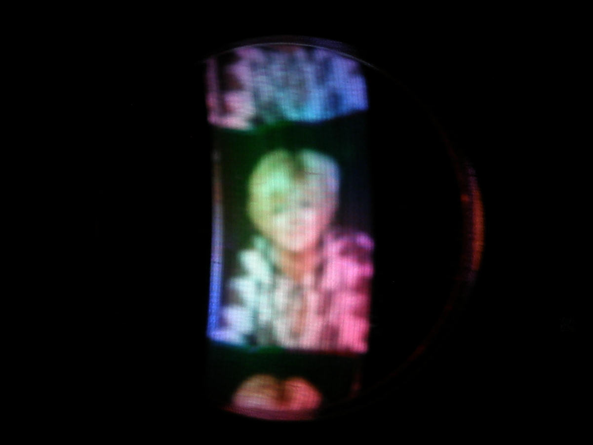
Labguy's NBTV Baird Televisor color pictures Here are the results of my efforts. You can see that the images have color purity issues due to the poor flatness of the white light diffusion. An opportunity for a future project, no doubt. Now, it's your turn. Go give this a try. Share your results and discoveries with me and I may add your info to this page. More info at the [NBTV - Narrow Band Television] web site. Thank you for visiting and viewing this page. [HOME] [ELECTRONICS PROJECTS] [PART 2] Created: February 3, 2015, Last updated: February 7, 2016 |