|
LabGuy's World: Cyclops, The 5AXP4 Project
NEWS FLASH 20141020: After working through this project for several days now, I have finally settled on a name for this project. From this day forward, this project will be referred to as Cyclops, the one eyed monster. Or just Cyclops for short. [PART 1 - START HERE] [CYCLOPS, PART 2] 
HIGH VOLTAGE PROJECT! The 5AXP4 five inch round television cathode ray tube PROJECT GOAL: Test my 5AXP4 and SC4679B-PSP five inch round CRTs and discover their purpose. I dusted off the old Scope Tube TV Project boards and tested it with a 3JP7 radar CRT. Still working. This got me to wondering if the Scope Tube TV board would have voltages close enough to test the five inch magnetic deflection CRTs that I just have lying about. 3D PRINTING ARRIVES AT LABGUY'S WORLD! FILM AT 11! Tinkercad Preview Images no longer available as of 20141102 Before we go any further, I must point out a landmark achievement. This is my first project that incorporates 3D printed parts! This is very cool. The cradle that you see the CRT resting in was 3D printed with ABS plastic over a period of five hours. The remaining pieces are the top half of the Face Frame and the two pieces that form the CRT Neck Support at the rear of the tube. These have yet to be printed. The pieces are held together and to a base substrate (3/4" piece of wood) by two threaded rods that are custom cut to length. The Face Support pieces are held by #6-32 threaded rod and the neck support uses #4-40 threaded stock. All hardware is either brass or stainless steel to avoid unnecessary magnetism in the region of the 5AXP4.
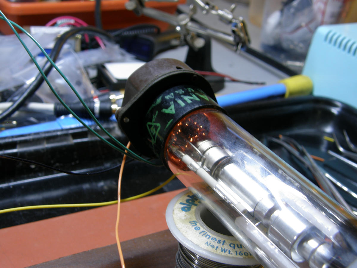
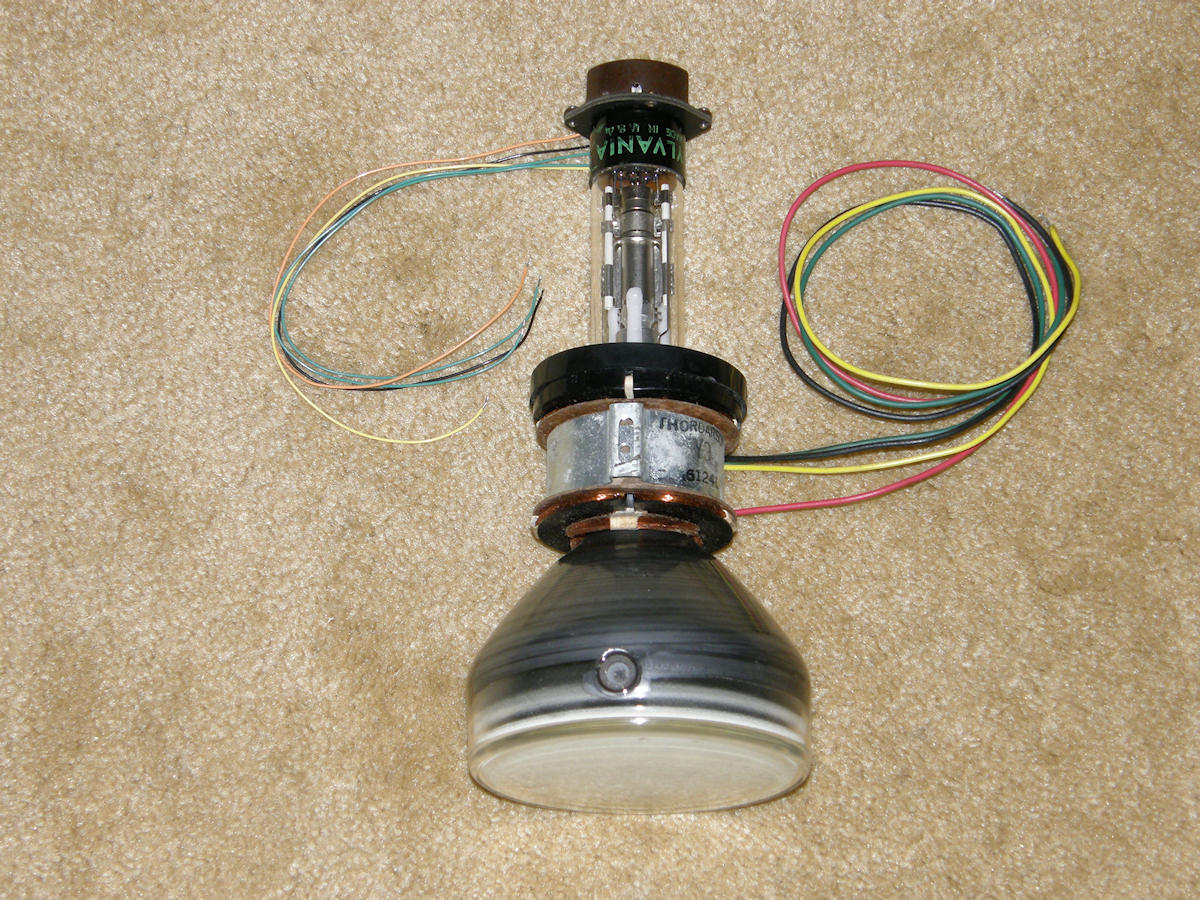
Above, enjoy the glow of a true to life tube heater. It didn't seem like it would work. But, it was worth a try. So, I swapped the tube connectors and hooked up the 5AXP4. Whadda ya know? It sort of worked. According to the data sheet, the 5AXP4 would like a nominal 14KV to really do its thing happily. That's fourteen thousand, drop you like a stone, volts of pain. This tube was designed, however, to operate over a very wide range of voltages so that it could serve as a small substitute picture tube for TV repair. The Scope Tube TV project board is running this 5AXP4 at only three kilovolts. The spot was unable to be focused as finely as one might expect. Attribute this to the A2 voltage being far too low at 3KV. My friend, Eric, tells me his 5AXP4 is working rather well, displaying Atari Asteroids(R), on about 6,000 volts. The new EMCO high voltage power supply is completely adjustable from zero volts to 15 kilovolts. So, I will eventually report back to you on what the lowest usable voltage really is. At the very least, this tube has been proven functional. See the [Sylvania 5AXP4] data sheet for the details. This tube was marketed as a TV service technician's tool. Instead of lugging that 200 pound 27" console BW TV back to the shop for service, the tech simply popped out the set's chassis and took that back to the shop. Once there, he'd pop the 5AXP4 into the deflection yoke, connect the leads and run the chassis. Watch a short video demonstrating a 5AXP4 test tubes on Bandersentv's Youtube channel: [Sylvania 5AXP4 Universal Picture Tube]
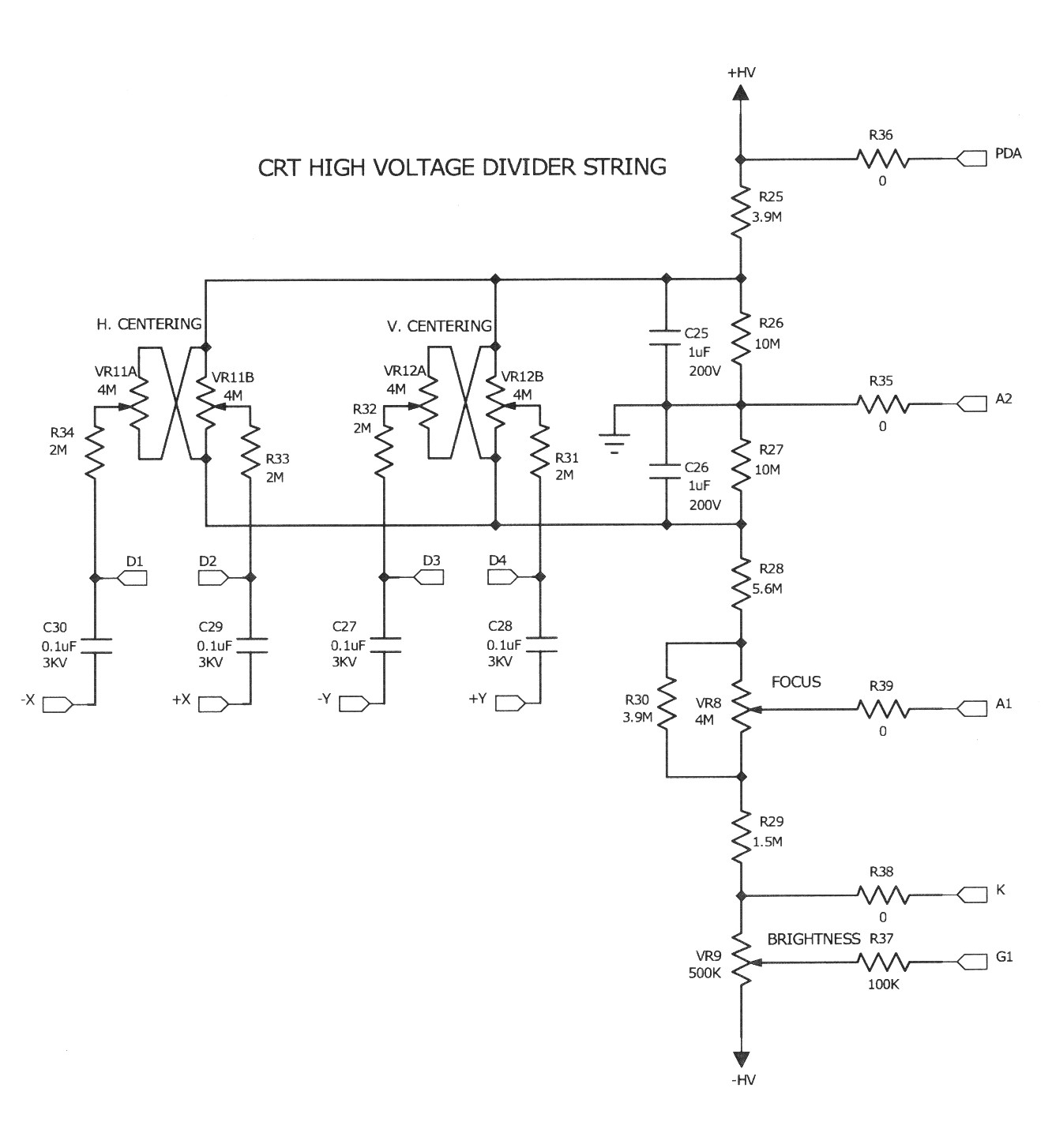
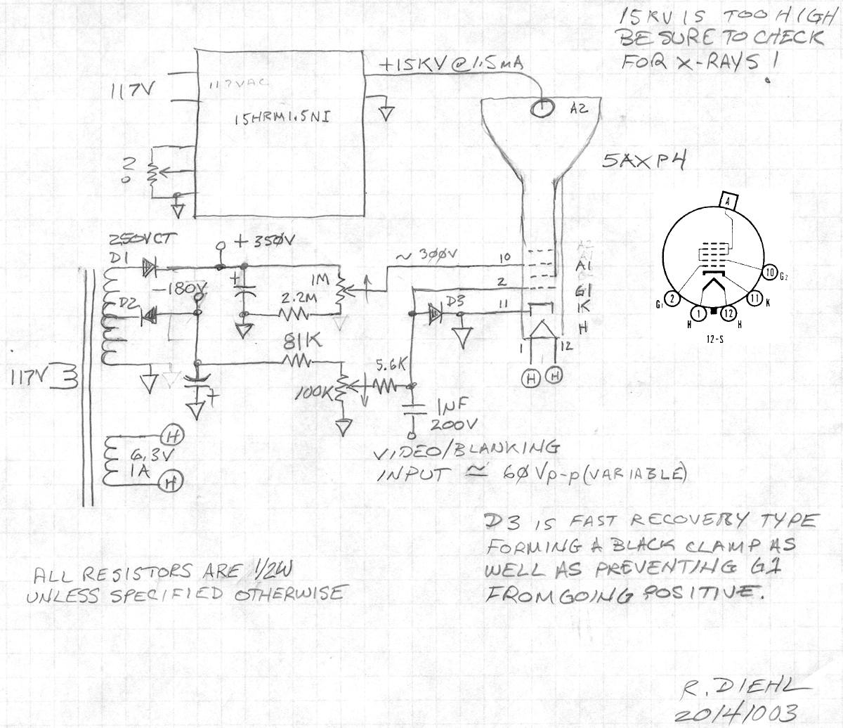
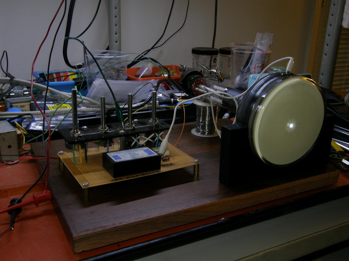
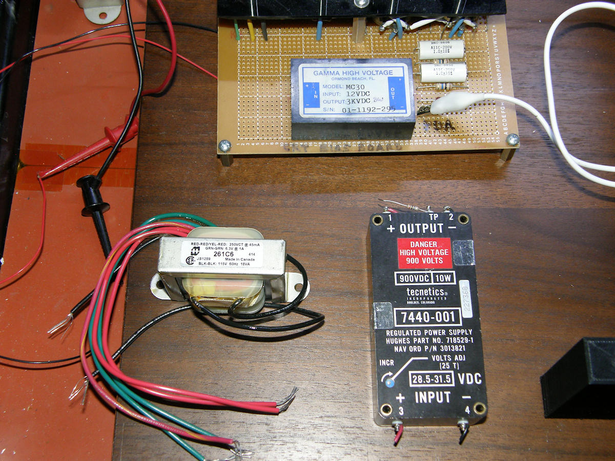
The first schematic shows Scope Tube TV CRT electron gun voltage divider. This is powered by the Emco 3KV high voltage brick power supply. The connections on the right side go to the electron gun elements of the tube. The deflection plates, in the case of electrostatic type tubes, connect to the 2Meg resistors coming from the wipers of the X & Y position pots. These are ignored, of course, in testing the 5AXP4. The second schematic shows one possible power supply arrangement. The lower end of the gun is biased from a table radio transformer, [Hammond Power 261C6], while the second anode is driven from a separate high voltage B+ supply. The one shown in this drawing, a Dell 15HRM1.5NI, is larger than the CRT and weighs at least twenty five pounds! I thought I found a much better high voltage power brick about the size of a chalk board eraser. Is this 9,000 volts? Upon closer inspection, it turned out to be 900 volts not 9KV. The search continues for a 10,000 to 14,000 volt power supply for this tube. The 900V power brick is visible in the next photo, lower right.
The table radio transformer, rectifiers and filters produce +360V and -180 volts. The +360V drives a voltage divider made up of a 1M ohm pot and a 2.2M ohm resistor in series. The pot is on the high side and covers a range of +250V to +360V. A1, the focus electrode, operates at a nominal +300V relative to the cathode. The G1 voltage divider consists of a 100K pot in series with a fixed 81K resistor. The pot is on the ground side of the circuit and produces a G1 voltage range of 0V to -100V. This should be more than enough to cut off the beam completely. Also note, that by design, it is absolutely imposible for the G1 voltage to ever go positive relative to the cathode. Speaking of which, in this design, the cathode is grounded. Zero volts on K. Still refering to the second schematic, above. The +360V Focus voltage is obtained by D1, a positive half wave rectifier. The -180V Brightness voltage is obtained from D2, a negative half wave rectifier. The bottom tap of the 250V winding is grounded. This way, D2 sees the 125V tap while D1 sees the full 250V tap.
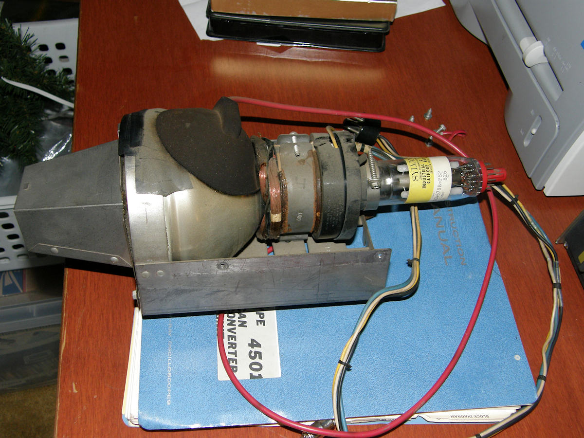
Since the 5AXP4 is a magnetic deflection CRT, I will cover that topic in the future. The deflection yoke that I purchased for this tube, on Ebay, has yet to arrive. Also in my arsenal of tubes, a five inch color flying spot scanner CRT. It comes from a Sylvania Home Theater Console Television that had its own carousel slide projector. The slides were scanned by this CRT and displayed on the console's 25" color tube. It ran directly from the same 25KV as the 25 inch CRT as well! Note the size of the insulated cup over the second anode.

TWENTY FIVE THOUSAND VOLTS AND X-RAYS. YIKES! The phosphor was a remix of P24. The new phosphor, called PSP, has an extended red component. However, it will still appear greenish to the human eye. Did I mention this tube is also a nice X-ray source! I hope to demonstrate the Sylvania SC4679B-PSP five inch flying spot scanner tube one day soon. Coincidentally, the research into my image dissector tubes led me straight back to photomultiplier tubes which are also a necessary compnent of any flying spot scanner. There are projects based on PM tubes in the works as well. One project is fed from another.... I need the 5AXP 4 running in order to use it to visually see if my magnetic scan circuits are working with good linearity and such before applying them to the image dissector tubes. Stay tuned! UPDATE 20141008 There are two brand new high voltage power supplies in our future. I will be purchasing these from [EMCO High Voltage] of Sutter Creek California. Not cheap. We are looking at a cost just north of $1,600 for the two power supplies. Both are rated for ten watts. One is variable from zero to 15KV. The other has arange of zero to 30KV. The first is for powering the 5AXP4. The second supply is for powering the SC4679B-PSP. The input power for these supplies is 24VDC at less than 1 amp. I puschased two tiny 24V, 1A switcher supplies from Digikey for $17.50 each yesterday. This solution will give me the safest, most reliable CRT power and it will acheive this NOW. Or in a shorter time frame than hacking power supplies from junk. Possible. But, not a very efficient use of time. That's a great question! Since I plan to run the deflection at virtually any scan rate that the coils are capable of, the high voltage supply must be separated from the deflection. Remember the problems I had trying to make the Akai VM-100 monitor run at 29KHz scan rate? Imagine what the HV will be if horizontal is running at 15Hz, the scan rate for classic slow scan TV. I believe the flyback's primary output would be.... smoke! One final critical point to make. It occured to me yesterday that I had no idea if the Sylvania FSS CRT was viable. That is, was the heater open or not? I tested it last evening and it works great! Still seeking pinouts for the rest of the gun elements in that tube. It would suk to drop nearly $900 for a power supply that ends up being usesless. UPDATE 20141009 The order was placed for the high voltage power supplies today. One of each, EMCO 4150 and 4300 positive output high voltage power supplies. The 4150 is the 15 kilovolt unit for the 5AXP4 and the 4300 is 30 kilovolt model for running the Sylvania tube. Both of the 3D printers, to which I have access, are broken. This is putting a delay on getting the rest of my CRT mounts fabricated. If I had not blown so much money on the power supplies, I'd consider having these parts printed commercially. But, that's not going to happen this month.

The design schematic for the 5AXP4 test fixture is completed. The project goal is now in focus. Click the picture for the larger view. Heater power, focus bias and brightness bias are provided by a small iron core power supply. The high voltage for the 5AXP4 is delivered from the EMCO 4150 high voltage power supply set for 14KV output. The EMCO supply itself is driven by a small 24 volt 1 amp switching power supply. Indicator lights are provided to tell when heater/bias is on and when the high voltage is on. Double AC switching is employed. Starting with both switches OFF, you turn on switch S1 first and wait for the heater to warm up in the CRT. This takes ten to fifiteen seconds. Then switch on the high voltage. Placing B+ onto the tube with a cold heater will damage the surface coating of the cathode. Possibly creating a K to G1 short. The EMCO supply provides a scaled voltage monitor output for convient setting. The formula is Vmon = (10/15,000) x HVout. At 14KV output, the monitor voltage will be 9.333V. Simple as pi. Last, but not least, concerning this design. The deflection yoke and G1 control are brought out to banana jacks. This tube is now a self powered magnetic deflection development test system. Both raster and vector scanning will be explored with this rig.
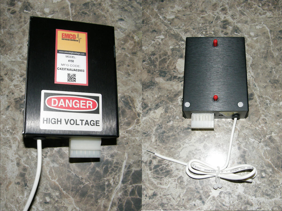
The EMCO power supplies have already arrived. I only ordered them the day before. Nice! I was lucky they were in stock. Lead time can be several weeks. This supply is quite compact, only sliughtly larger than a pack of cigarettes. Approximately 4" x 3" x 1.5" and is mounted by a pair of threaded studs on the bottom. I presume this mounts to a heat sink. The connector shell and pins are also provided by EMCO. The high voltage lead is a measured 26 inches long. I will attach a standard J1-22 high voltage connector to this lead for attachment to the CRT. 20141011 - Moved the Sylvania SC4679B-PSP scanner CRT to the [Color Flying Spot Scanner Project] page. 5AXP4 MAGNETIC DEFLECTION SYSTEM - 20141012
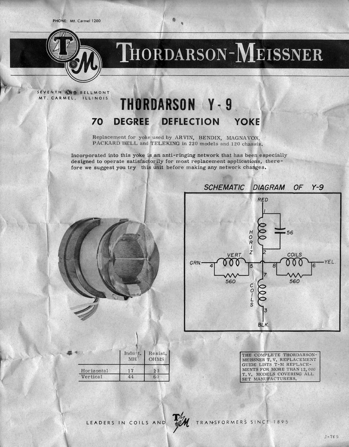
Moving right along... A Thordarson-Meissner Y-9 old timey CRT deflection yoke! Early 1960s vintage NOS (new old stock) part for sure. This will be the (first?) deflection yoke to be tested on the 5AXP4. This is a high impedance vacuum tube yoke. So, ultimately, it may not work the way I need. Low voltage modern circuits may not be able to push enough current through the high resistance of the coils. But, this is where I will start since it is the only one available for now. Let's hook the yoke to a power supply and measure its paramaters. 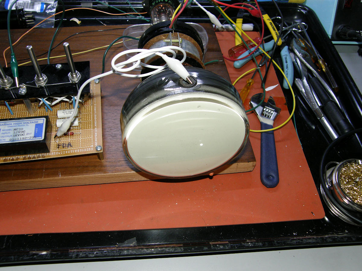
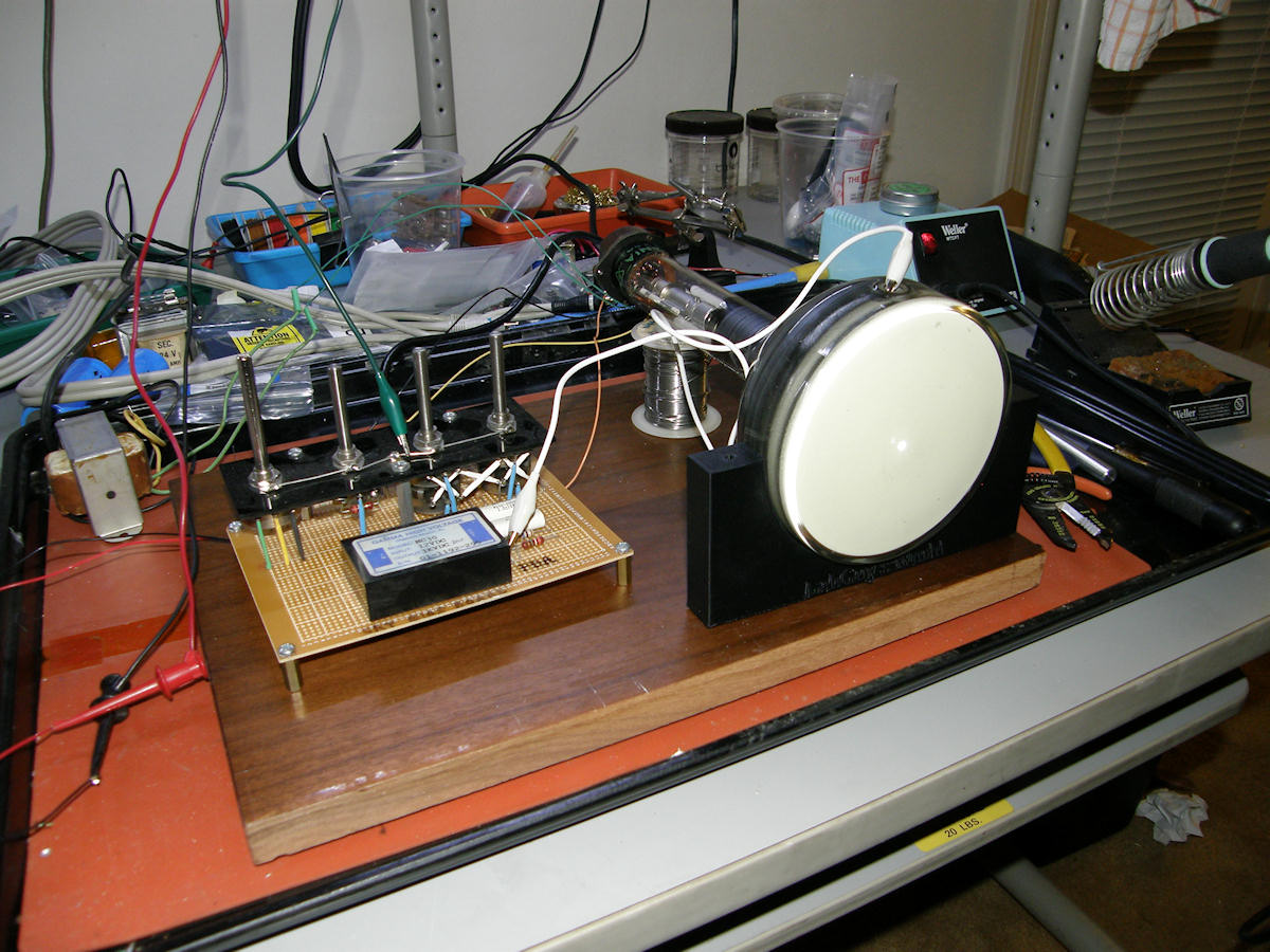
First magentic deflection of the 5AXP4 - 20141012 Using a current limited DC power supply, I was able to do some cude testing of the deflection yoke. Running the 5AXP4 on my Scope Tube TV board while driving measured DC current through the deflection coils. Vertical coils run about +/-5 volts and about +/- 90mA. Horizontal deflection moved the spot with only +/-2.5V and about +/- 125mA. This is reasonable conisdering the beam in the CRT is only running on 3KV. It is extremely easy to deflect. Like increasing pressure in a fire hose, as electron beam voltage increases, it takes more energy to bend it. What is really happening is that the electrons are speeding up and spending less time in the region of deflection. Thus they bend less. When the tube is eventually operated on 14KV, deflection power requirements will increase by quite a bit. Watch! First dynamic test of the 5AXP4 deflection yoke - 20141012 What a fun video. I liked making that one. Enjoy a recorded demonstration of the 5AXP4 being deflected like an oscilloscope, using the output of an old stero amplifier. PROGRESS REPORT 20141015 Still being stymied by 3D printing issues. But, I have a lead on a resource that may deliver next week. Stay tuned on that. 
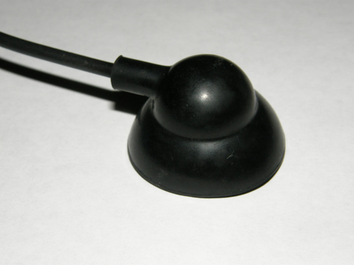
The Just Right second anode connector - 20141015 In mundane news, I've successfully located an anode connector that is just right. It is the lead from a small broken flyback transformer I found at the surplus store today during lunch. These are not hard to find in general. But, finding one that appears to be specifically made for a smaller CRT is uncommon. The anode contact of the 5AXP4 is only half an inch back from the face of the tube.The more common "standard" anode connector is about twice the size of this one and will ultimately hang over the face of the CRT. It attaches to the tube by two springy wire clips that grip the inside of the contact shell. The silicone rubber cover provides insulation and prevents accidental contact with the high voltage. 
100 to 240VAC, 50 or 60 Hz, in - 0 to 15,000 volts out - 20141015 The 24 volt 1 amp DC power supplies arrived yesterday. These, in turn, will power the EMCO high voltage power supplies. I will be duplicating a lot of this circuitry in the [Color Flying Spot Scanner Project] as well. Note the white high voltage wire is currently unterminated. The round connector above will be attached to this lead and attached to the side of the CRT in the finished project. 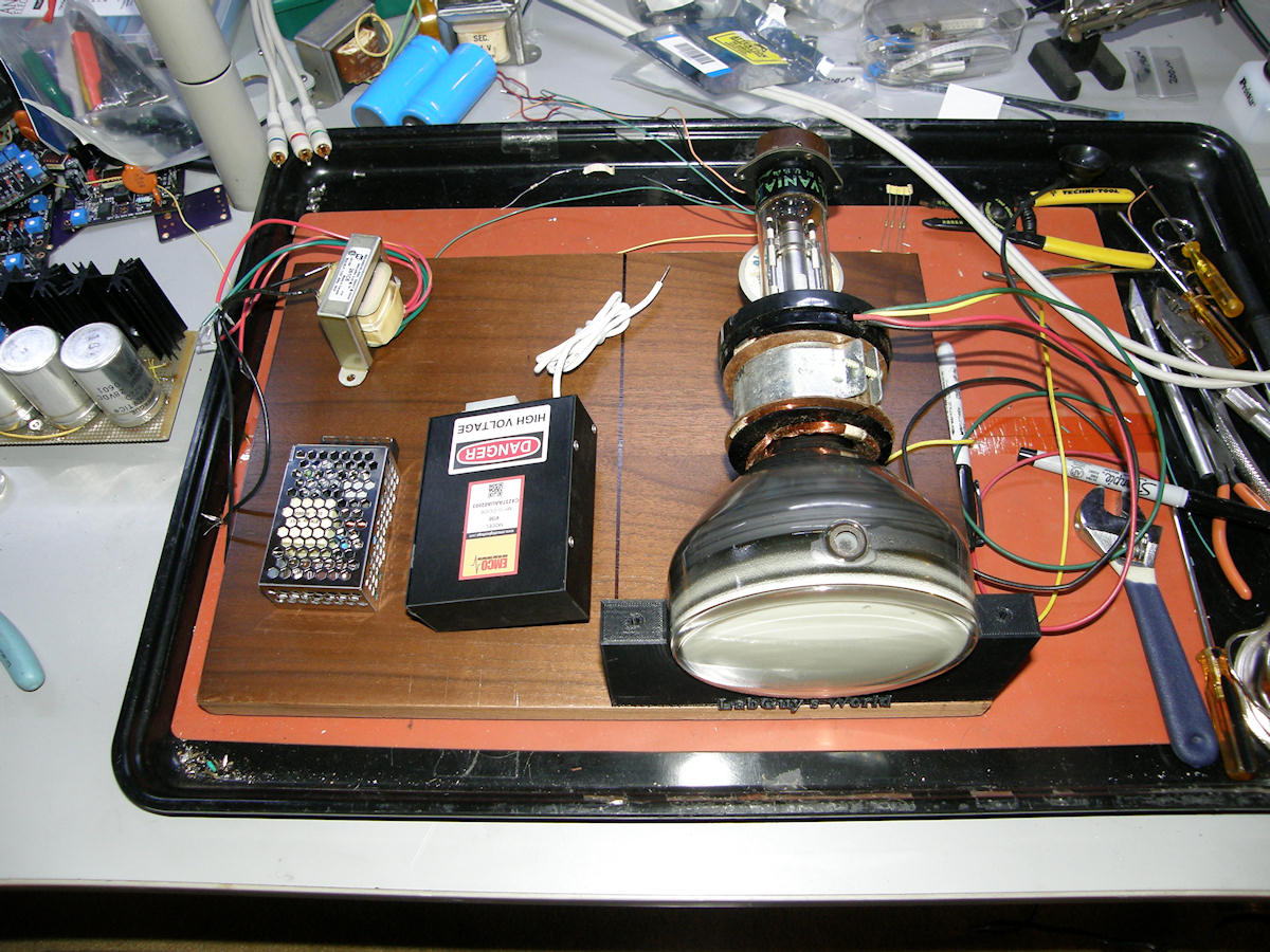
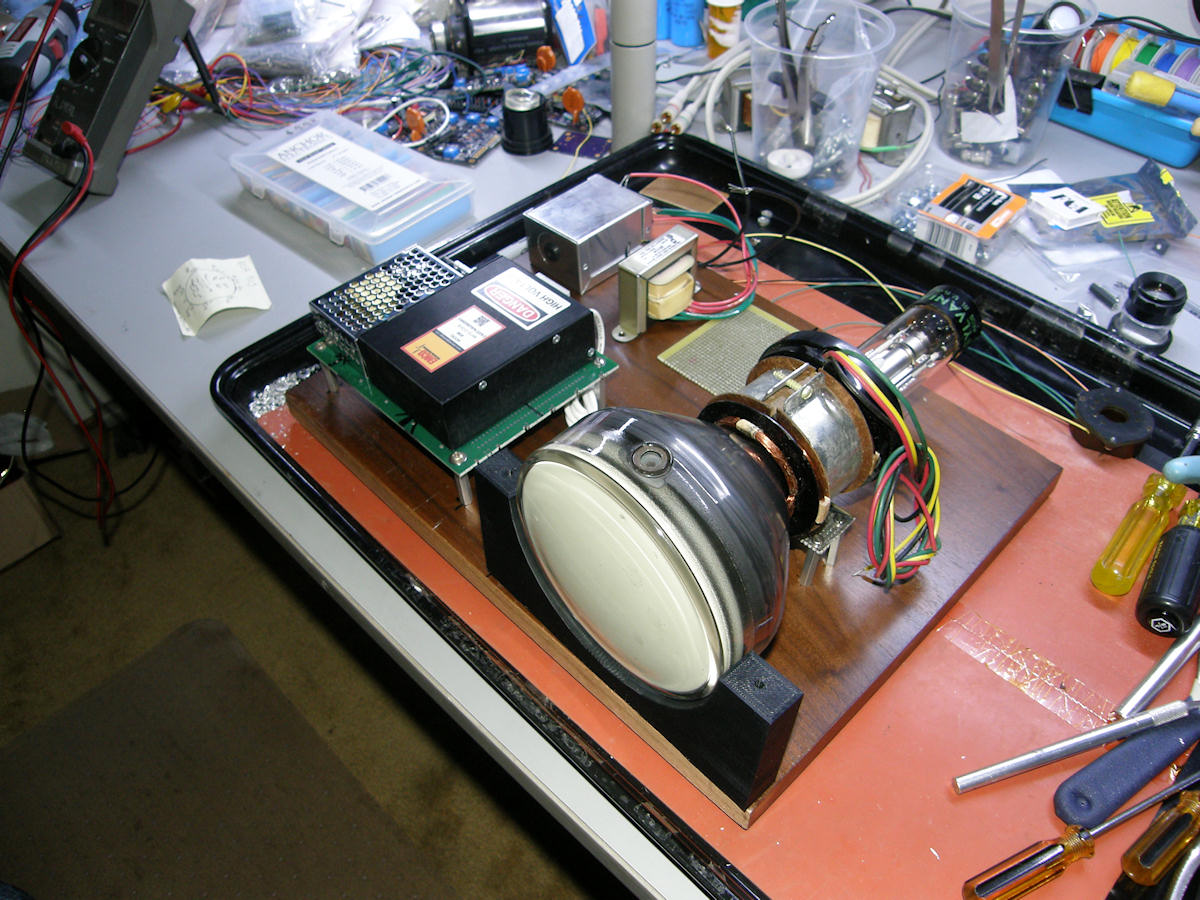
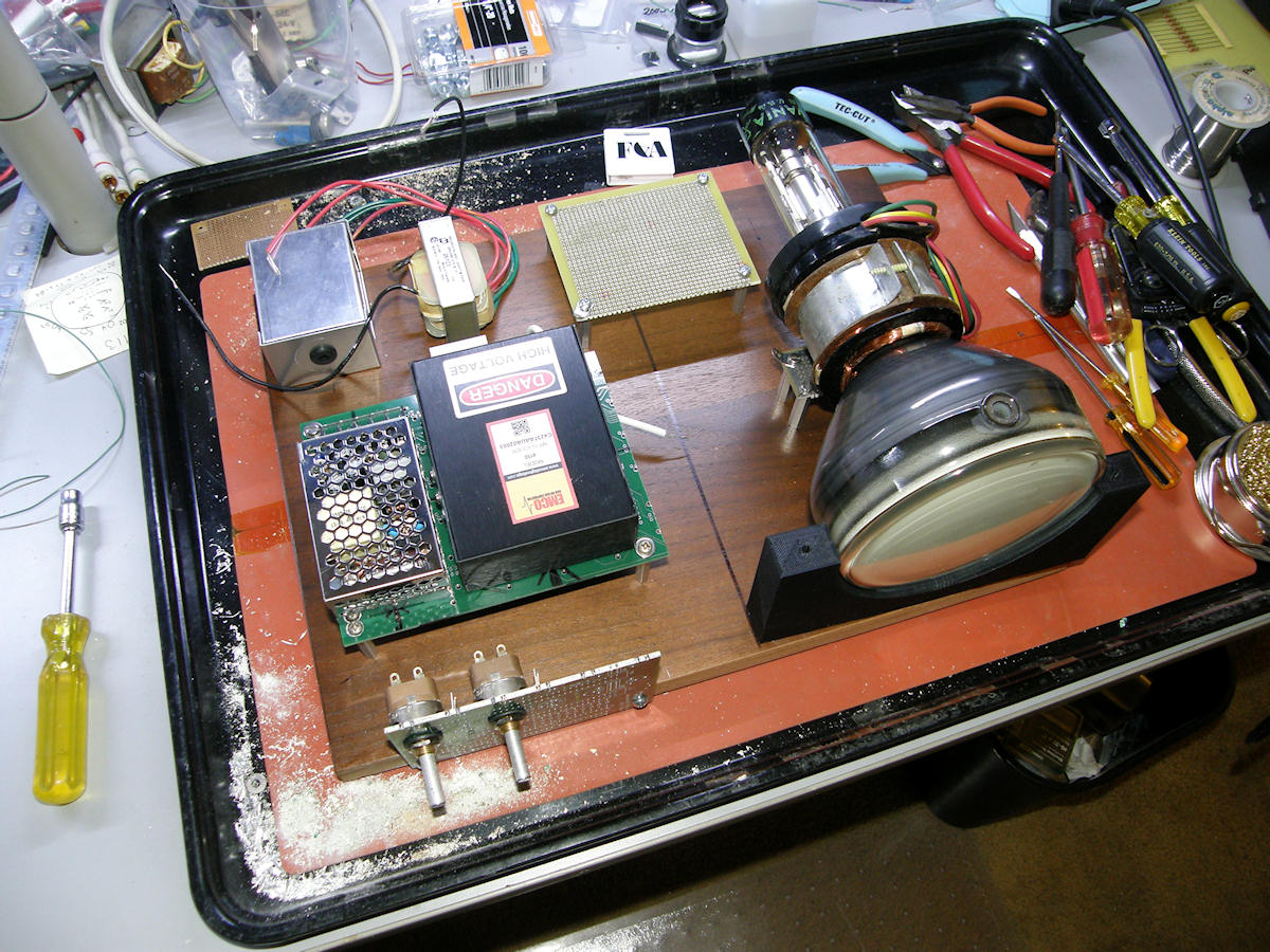
First fitting. Choosing placement of components on baseboard - 20141015 It is time to start placing the parts into their final positions and see if it will truly fit onto this base board. There will be a circuit board to support the rectifiers, filter capacitors, resistors, pots and blanking / video input connector for the electron gun control section. Not visible is the #8-32 mounting nut on the bottom of the deflection yoke. It is in a slot allowing the yoke to slide forward and back. I will build a bridge like support that stands 1-3/8" off the base board. Think scrap PCB and standoffs. The support bridge will also have a slot for the mounting screw. It is oriented 90 degrees to the first slotted nut in the yoke. This will allow me to locate the yoke precisely and support it separately from the CRT. Having the yoke bolted to the base means it can't break the neck of the CRT if the board is dropped. This is a particularly tough light emitting bottle. But, everything has its limits. PROGRESS REPORT 20141016 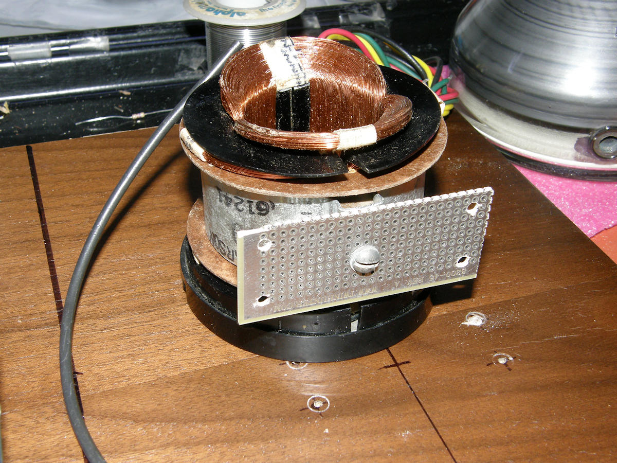
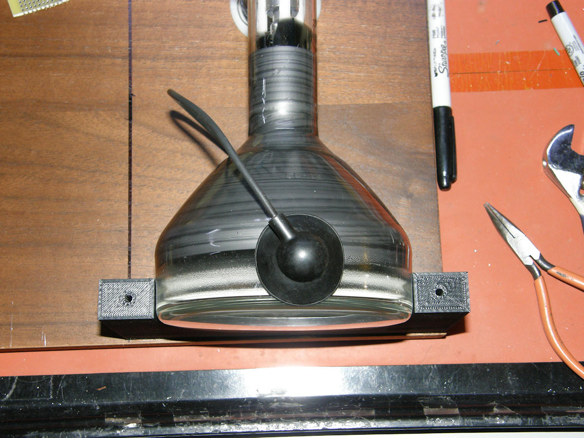
Deflection yoke support and second anode connector - 20141016 It's time to start fitting the pieces together. This deflection yoke is designed to be mounted separately from the CRT. It requires support from below. A #8-32 threaded nut set loosely in a channel allows for fore and aft motion of the yoke. The CRT will sit in its own set of of printed plastic supports. You can see the holes where the threaded spacers will attach to the base board and yoke. I cleaned the high voltage connector with isopropyl alcohol and it now looks brand new. The upper plastic support has a cut out to accomdate the high voltage connector. 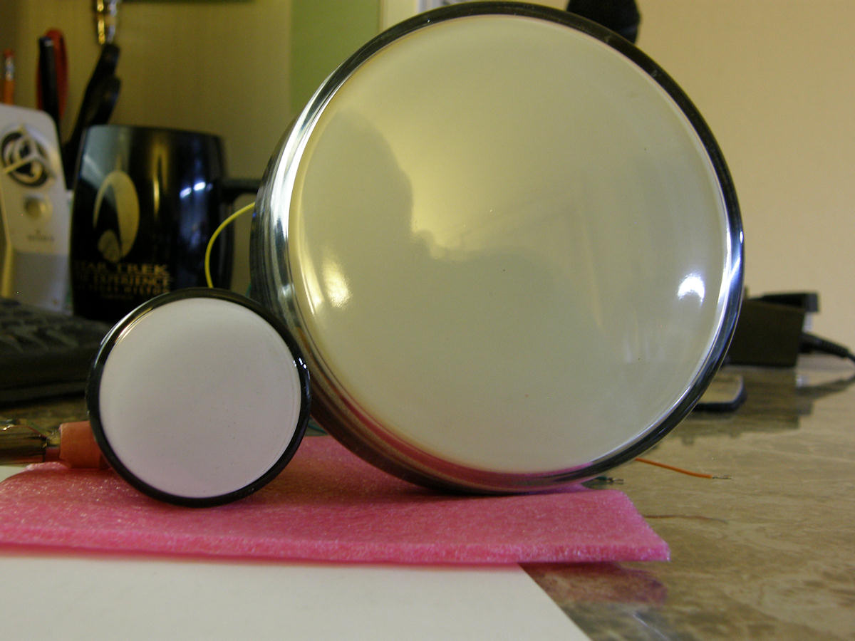

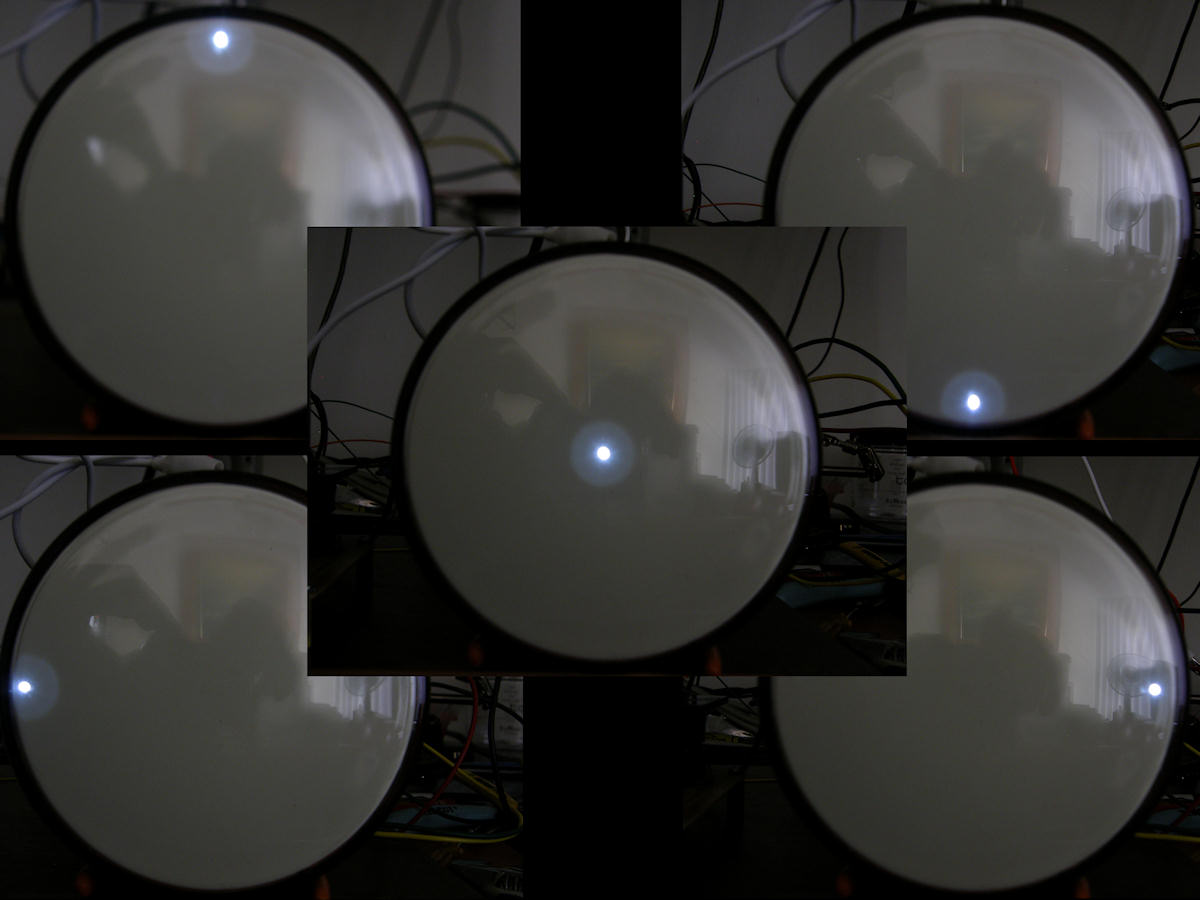
Let's shine UV light on the P4 phosphor in this 5AXP4 - 20141016 Let's grab the ultraviolet flashlight and see what glows. To my surprise, the 5AXP4 started glowing. Normally, P4 phosphor does not glow under UV. This is an older blend of two phosphors, a yellow as we see here and a blue. Yellow and blue blend to make white because you are adding a primary color to its opposite secondary color. The result is white light. The wavelength of my UV flashlight only stimulates the yellow component. Electron stimulation will make the blue phosphor glow as well and the screen will appear white with that classic P4 bluish tint. 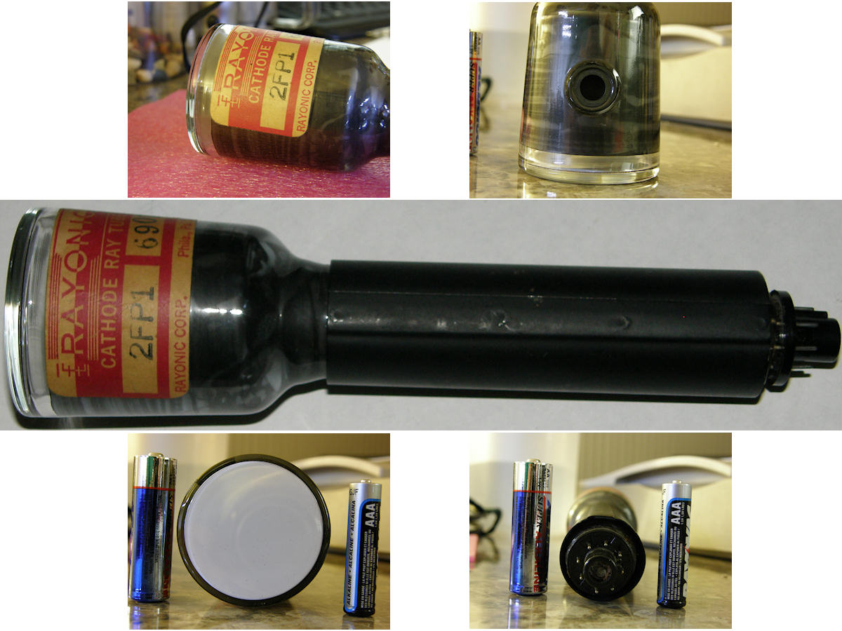
Rayonic 2FP1 - 20141016 The smaller tube in the previous photo is my latest acquisition. A Rayonic 2FP1. I place this tube in the photo as reference. This tube is a two inch magnetic deflection CRT with P1 oscilloscope phosphor. A variant, the 2FP4 was used in the 1958 Philco Safari, the very first commercial transistor television on the market. Documentation for that set is available and I can get the pinout and voltage for this tube with ease. The glass in the 2FP4 is very heavy and thick. This is no doubt a ruggidized military tube. My guess is night vision viewfinder. More fun with this funky old tube must wait for another day. In the competely amusing department: Google searches for information about this tube turn up pictures of this very tube. Only. It is the same serial number in all images everywhere. This guy gets around! Will being searching my photo archive from around 2000 when I get time. I am beginning to suspect I may have owned this tube once before! 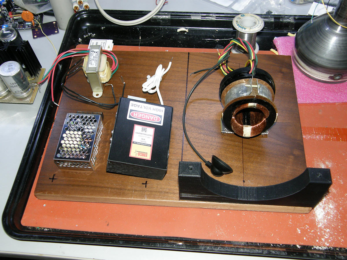
Getting back on topic... - 20141016 Here is a parting shot of the project layout. Imagine the possibilities. PROGRESS REPORT 20141018 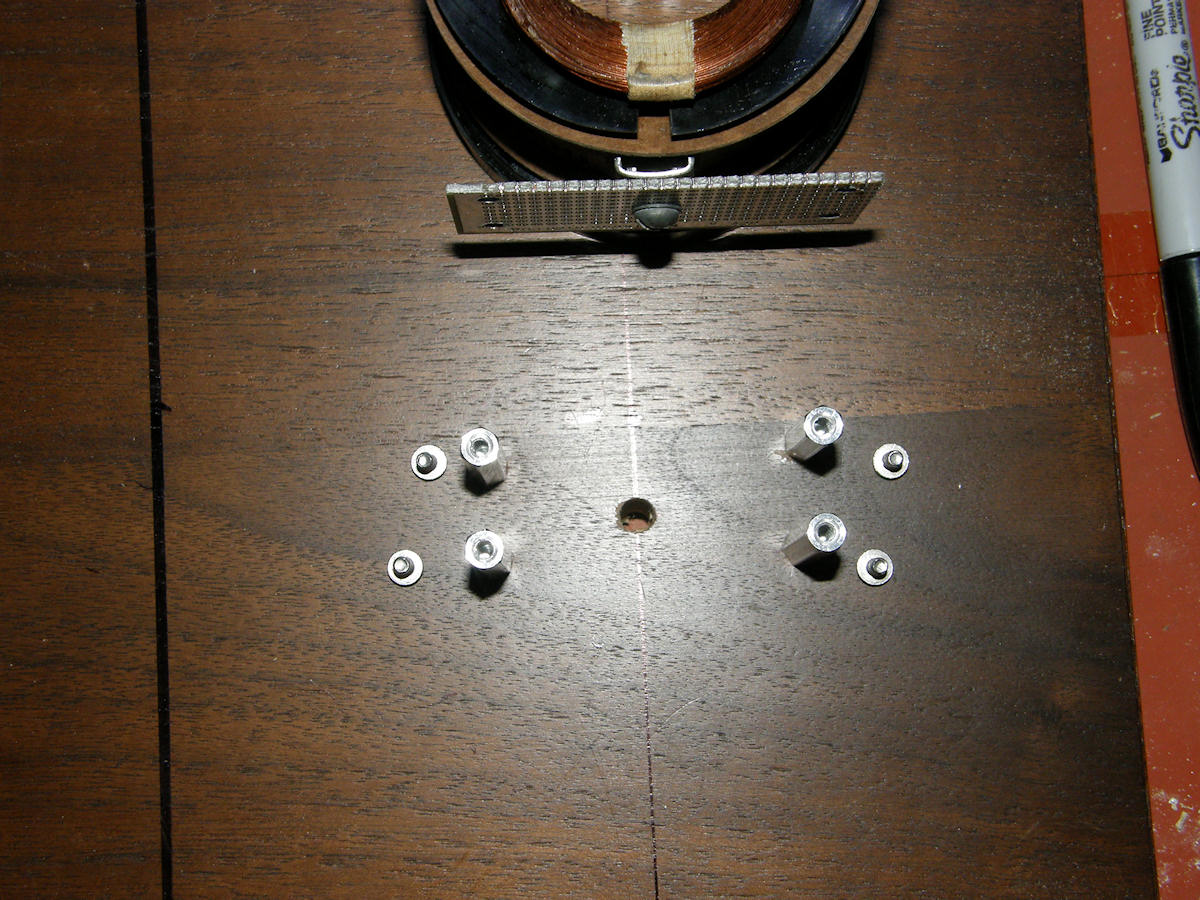

Supporting the deflection yoke assembly - 20141018 This deflection yoke is of the type that was supported separately from the picture tube. It would sit atop a metal frame that was attached to the chassis. In modern sets, the yoke is an actual part of the CRT. Not so in the early days of easy to break glass cathode ray tubes. I have attached the yoke to a piece of scrap PCB material, fibergalss with a skin of copper to serve as a ground contact as well. The hole that is drilled through the base board, dead center under the yoke, is for screwdriver access to the yoke alignment screw. This allows for final alignment when everything is finally assembled. When this screw is loosened, the yoke can be moved forward and back about half an inch in order to position it on the tube's center of deflection. 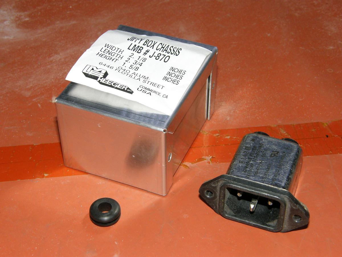
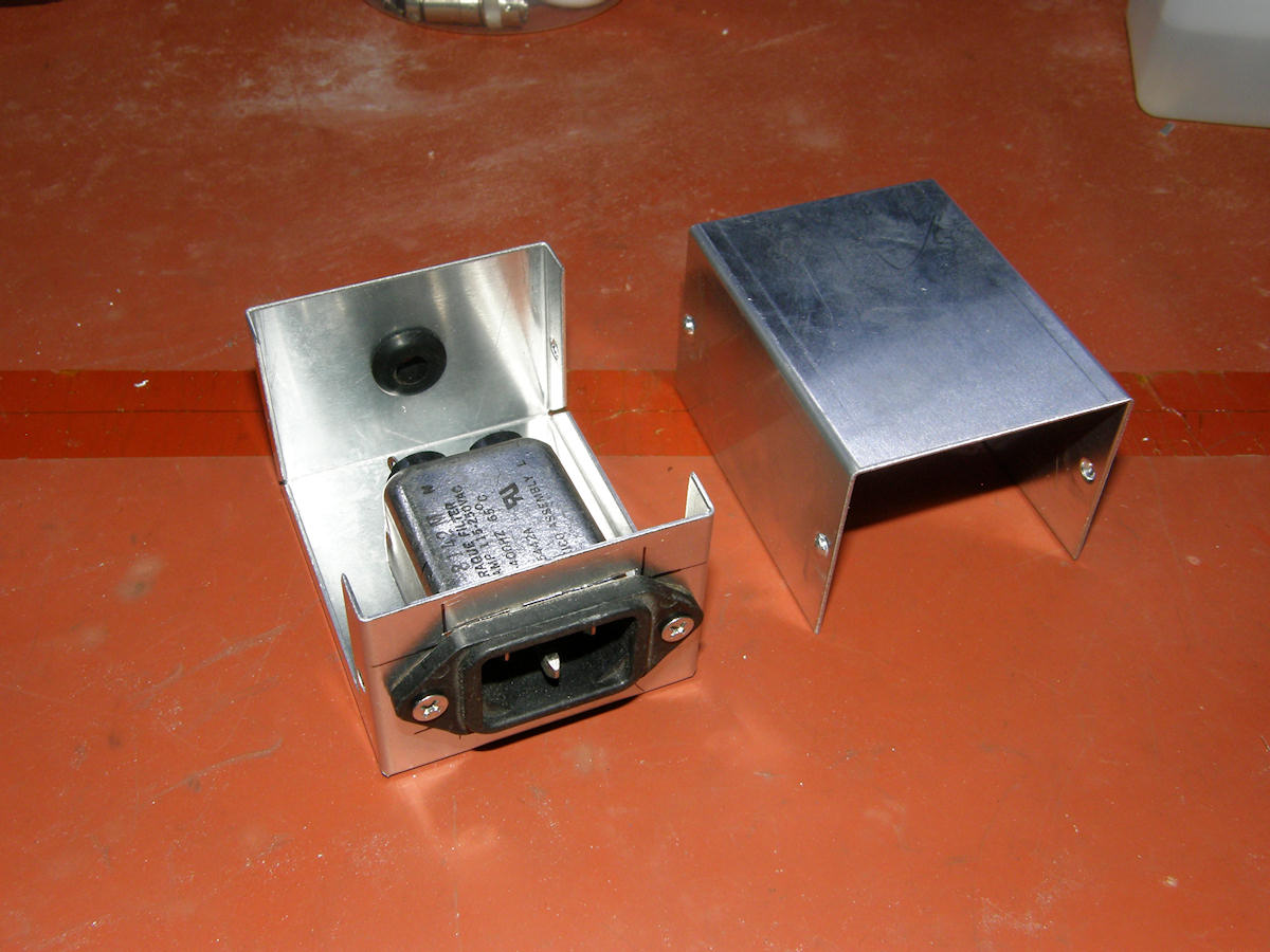
AC power entry - 20141018 The AC power entry allows the attachement of a standard EIA style power cord to the project board. It contains the entry module, a unit that not only receives the cord, but also contains a jim danday power line noise filter. This unit is housed in a small aluminium project box. I cut the main hole in it with a nibbling tool. On the back end of the box, I drilled 3/8" hole and installed rubber grommet to prevent chafing the wires where they pass through the wall of the box. The half of the box that holds the entry module will be held to the base board via two short wood screws. With the cover installed, we are kept safe from accidental contact with AC line voltages. 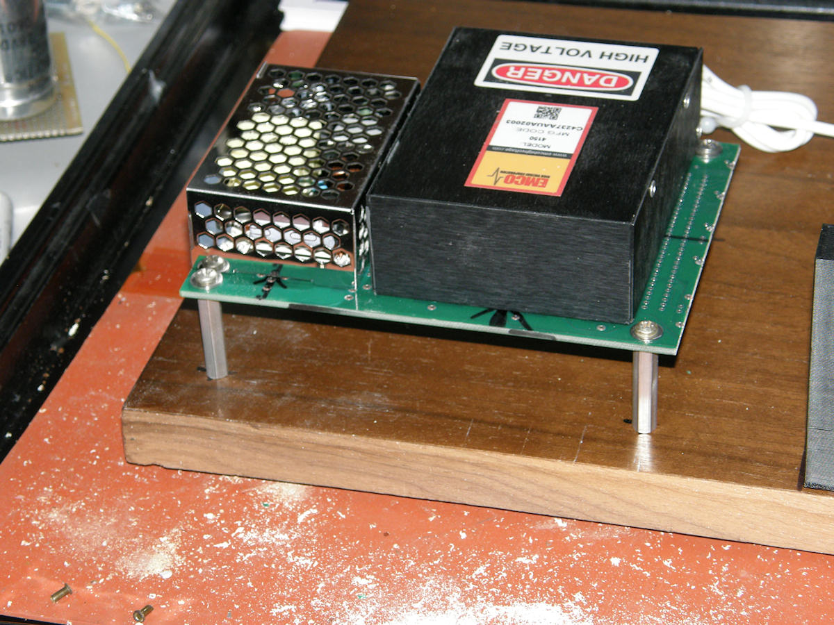
High voltage power supply assembly and more placement - 20141018 The two modules that comprise the high voltage power supply are mounted together to a piece of surplus PCB with four aluminum standoffs forming the legs, which I am calling a table. Both supplies required fastening from the bottom. So, they had to be raised up from the base board. The smaller 24V supply attached with two 2mm screws and the EMCO supply is held down with two #6-32 kep nuts via the male stud bolts provided. Beneath the table, a solder lug will be attached to each power supply directly. A ground wire will be tied to these and all other major ground points on the actual circuit board. These will all meet at a common node, in a star configuration, the common node to be located just behind the AC entry module. Another bit that will need fitting and some more thought is the bias voltage board. This is the circuit attached to the small radio transformer and supplying the 5AXP4 G1 brightness and A1 focus voltage controls as well as the two series-ganged AC power switches. The rectifiers and filter capacitors will be on the board. The brightness and focus control pots will be mounted separately on a front panel. I purchased two panel mount potentiometers with built-in switches just for this function. The brightness control is MAIN AC off/on. The focus control is the high voltage off/on switch. This works out very well as I will not have to figure out how to mount the switches now. Win win! The current plan is to place the two pots on a metal front panel mounted in front of the HV supply table. The eight banana jacks will also be mounted to the front panel. The HV supply table mounting holes have not been drilled in the base board yet. So, there is some play in the placement of the various modules. PROGRESS REPORT 20141019 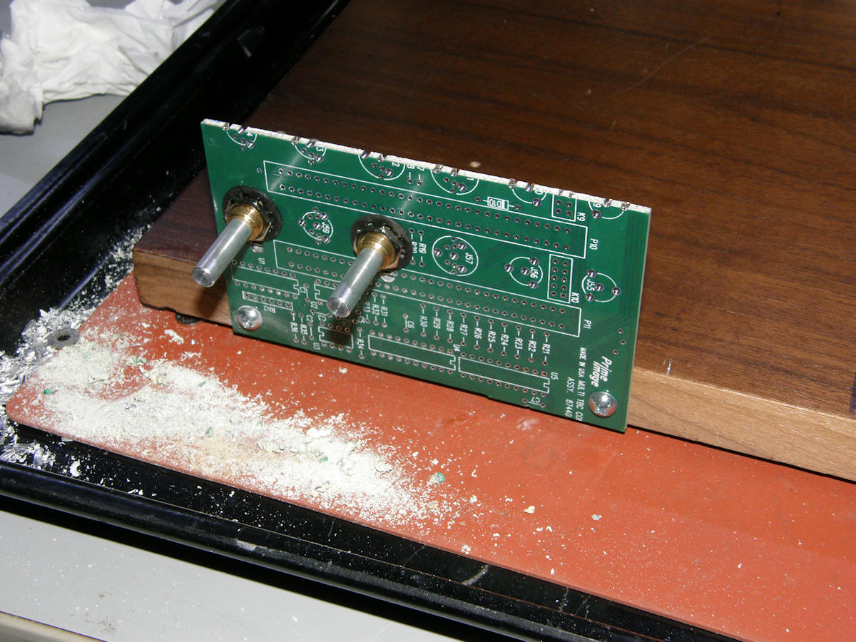
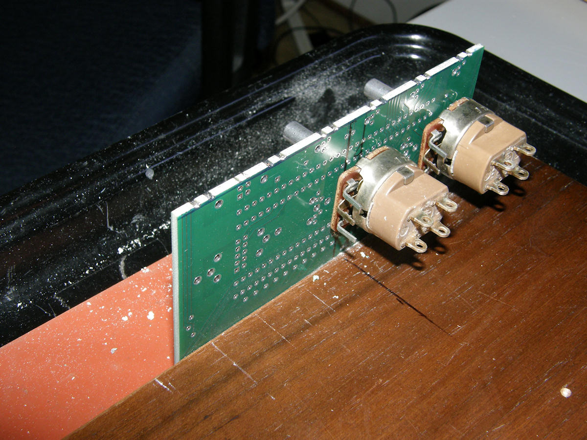
Mounting the brightness and focus controls - 20141019 A simple scrap of PCB makes an excellent, simple, front panel. The PCB has ground plane on both faces and the two pots are grounded together by good fortune. All exposed surfaces will be grounded in the final product. Each pot has a push/pull off/on switch. The switch on the brightness control will be for Standby Power. The switch on the Focus control turns high voltage off and on. The pots are left justified on the panel as I plan to install the power pilot light LEDs to the right of them. I feel more comfortable placing the low voltage LEDs a safe distance from the pots. The focus pot has +350 volts on it. The LEDs will be placed in the two smaller silk screened circles toward the right of the panel. These old circuit boards have natural landmarks which sometimes can be repurposed to our needs! 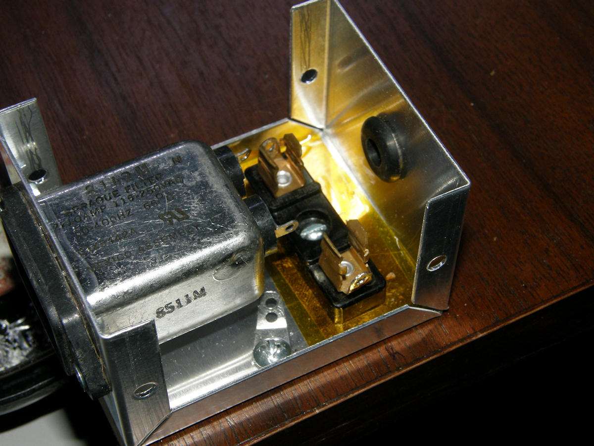
AC entry box and electrical safety components - 20141019 The AC entry module is attached to the base board now. The fuse holder fits nicely inside the aluminum project box and thus does not have to sit exposed on the project base board. Two layers of [Kapton tape] beneath the fuse holder will help increase the insulation between it and ground. The solder lug visible in the AC entry box is the primary safety ground point of the system. Not visible in this view, is the ground lug that is spot welded to the AC entry unit itself. This lug is located below the two line connections that are visible. The AC unit has a very small ground lug that can not hold all the wires that it may need to. So, I will use a very short heavy guage solid copper wire to connect that to the ground lug in the bottom of the box. This is all done on top of the fact that the case of the entry unit is in intimate contact with the project box by default. You can never build in too much safety. LABGUY'S SAFETY RULE #65.1: It is not connected electrically until it is soldered or welded. If you look closely at the assemblies on the main board, you can see a solder lug on the corner of the yoke support table and the rectifier and bias PCB. Under the high voltage table, each power supply has a ground lug as well. A ground wire will also be connected to the front panel PCB rendering the control shafts at ground potential. Since this project is not constructed on a traditional metal chassis, extra care must be taken to insure no exposed surface is at any voltage other than ground. No wiring has been started as, at some point, all the assemblies will be srtipped down and many of the parts will be painted traditional* optical black. Will also hold out until the 3D printed parts arrive and everything can finally be fitted together. * A tradition at Labguy's World since last year! This page is long enough now. Breaking it off here. Follow the link below to Cyclops, Part 2. [HOME] [ELECTRONICS PROJECTS] [CYCLOPS, PART 2] Created: October 5,2014 Last updated: November 9, 2014 |