LabGuy's World: Color Flying Spot Scanner Project
 Block diagram of Color Flying Spot Scanner for photographic slides 20141011
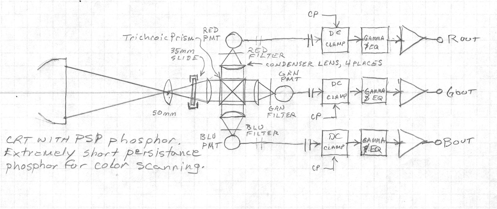
PROJECT GOAL: Scan 35mm slides and see them on TV. A high intensity blank raster is produced on the face of what is essentially a five inch projection CRT. It is run on extremely high voltage, twenty five thousand volts, in the case of the Sylvania SC4679B-PSP. This blank raster is projected through an objective lens and focused onto the photographic slide. As the scanning spot traverses the image in an orderly fasion, left to right, top to bottom, light passing through the slide is sent to a color sensitive photo detector. The photo detector consists of three photomultiplier tubes, their support circuits and color separating optics. The optics divide the white light into red, green and blue bands and routes the light to the appropriate photo tube / color channel. Color separation will be performed by the same trichroic color prism and color filter gels I used for the [Tiny Triniscope Project]. The photomultiplier tubes convert the light into voltage. Each tube sees the scanning light after separation and further filtering. Three channels produce simultaneous red, gren and blue video signals. The R,G & B signals are DC clamped prior to passing through a gamma correction amplifier. This compensates for the density of color slide film of the 1960s! How cool is that? Once gamma corrected red, green and blue signals are recovered, they may be sent directly to a monitor for display or to an encoder for further processing. More on that later. The most important component in the system is the phosphor in the CRT. For scanning, two qualities are desired. Broad spectral bandwidth and rapid light decay. That is to say, the phosphor must produce a usable amount of red, green and blue light, despite not looking like what we humans call white light. P24, the original standard color scanning phosphor, looks very green to the human eye. The imbalance is corrected with color filters in front of the photo tubes to achieve good white balance. P24 had a decay time, to 10% of peak brightness, of 1.4uS. Sylvania's PSP phosphor used in this tube, decays to 10% brightness in a only 120nS. Rapid decay is needed to get the highest scanning resolution possible. The inevitable frequency response distortion is reduced by an equalizing network in the video process amplifiers. 
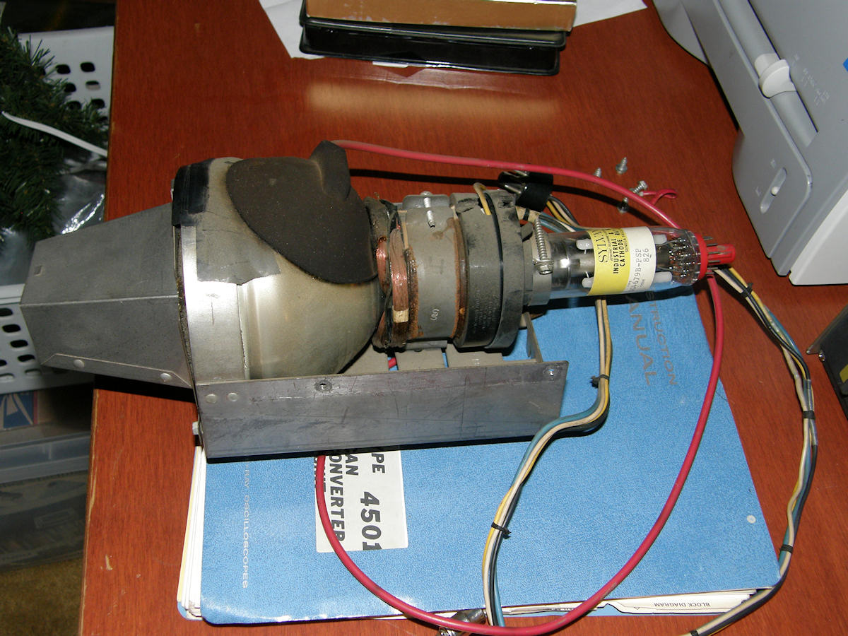
 HIGH VOLTAGE PROJECT! - SC4679B-PSP Color Scanning Cathode Ray Tube - X-RAYS! Enjoy the kitsch! The heart of this project is the special scanning tube. It is five inches in diameter and twelve inches long. It is mounted in a special sheet metal enclosure which also includes a cover piece, not shown. The reason for the sheet metal is X-ray shielding. 
The right tools for the job. A geiger counter and a 40KV high voltage probe When electrons are accelerated above 16KV, they can cause X-rays to be emitted when they strike certain materials. A CRT of five inch screen size would normally operate in the region of 10KV to 15KV, in the directly viewed mode. This one is being operated at 25KV (25,000 volts). The scanner tube emits X-rays in normal operation. That's a fact. In order to construct this project safely, one must have the right tools for the job. Above, you see my geiger counter and high voltage probe. These tools will remove the guess work from the process and keep me much safer as I proceed. This project is living mostly on paper at this point in time. The 25KV high voltage power supply has already been purchased. Documents have been unearthed and have dramatically improved the project's chance of success. There is a complete explanation of the process of the original Sylvania scanner system, from the IEEE, and a few patents articles. See the citations at the end of this article. More will be added as they are discoverd. I will attempt to duplicate the Sylvania-Color-Television-Slide-Theatre-Model CFNP20BT in principle. 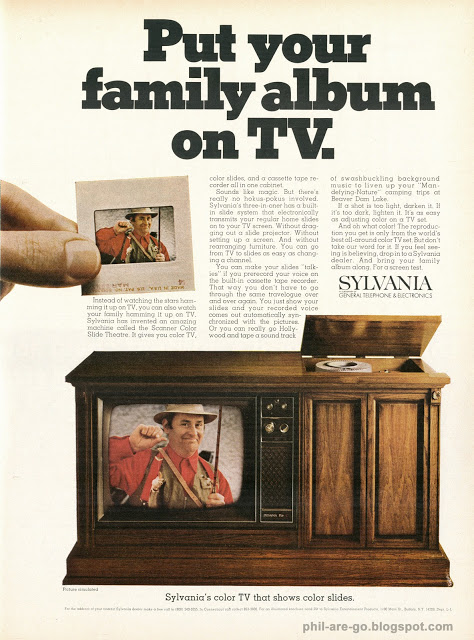
1968 Sylvania Color Television Slide Theatre Model CFNP20BT Photo found at: phil-are-go.blogspot.com Once again, I'd like to thank Cliff Benham for his valuable assistance. He identified the model number of the actual Sylvania product, model CFNP20BT. With that tid bit of information, I was able to immediately purchase a copy of the service literature. From that, I should be able to learn the pinout of and, hopefully, the correct voltages to operate this scanner tube. UPDATE ! UPDATE ! UPDATE ! 20150409 Cliff Benham is the luckiest guy I know. He recently obtained, and is actively restoring, an RCA Colorama NTSC flying spot slide scanner! Read about it at the Early Television Foundation website: [RCA Colorama Flying Spot Scanner]. The idea, in the early 1960s, was to sell these to dealerships and service shops to provide a source of color video during the parts of the day when the broadcasts were black and white. It is possible that RCA sold very few of these. In all my years, I'd never encountered even a rumor of this device in my studies. The cost of the thing must have been enormous too! Quite likely over $1,000 in 1962 dollars. Possibly a couple of grand. This is why I don't think many were sold. The article contained enough information for me to identify and obtain the same three photomultiplier tubes as used in the RCA Colorama scanner. Two RCA 5819 and one RCA 6217 two inch photomultiplier tubes. The latter has a bi-alkali photocathode which is important to enhance red sensitivity. These tubes normally favor the blue to ultraviolet parts of the spectrum and are insensitive to red and IR. I have managed to obtain all three photo tubes now. In addition, the PSP phosphor in the Sylvania scanner CRT has enhanced red. So, maybe my attempts will have good signal to noise in the red channel. 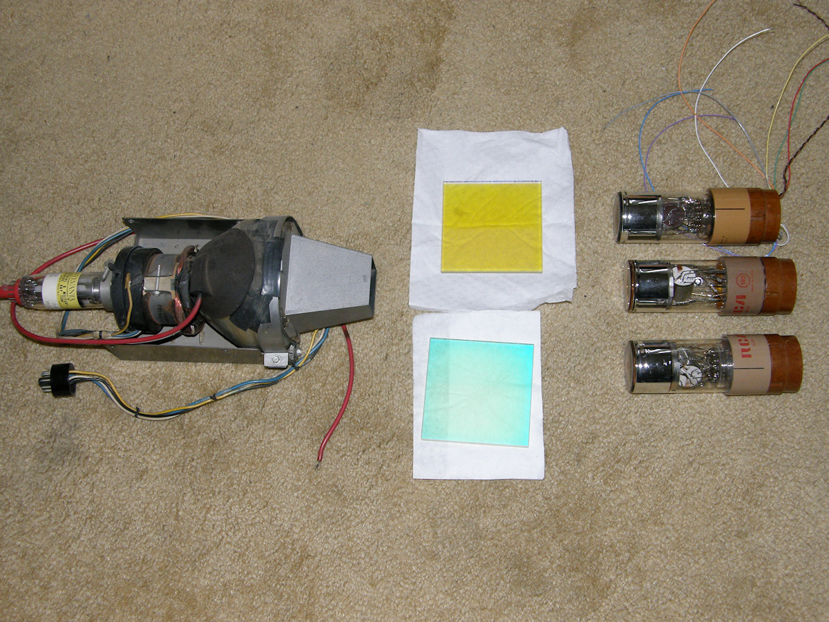
Color scanning CRT, dichroic filters and photo multiplier tubes I just purchased the color optics from a scrapped General Electric PE-250 four tube color television camera. This camera contained an image orthicon tube in the luma channel and three vidicons or plumbicons in the color channels. The optics for this are huge! The two color separating mirrors are four inches by four inches. This simplifies the system as compared to using the smaller trichroic prism. The big filters eliminate the need for the relay lenses and their light loss. Not shown is the Emco 25Kvolt power supply for the CRT. This is an excellent start to the optical system. I have decided to use a black and white video monitor to drive the CRT. I don't want to design deflection systems at this time. The three photomuliplier tubes will produce red, green and blue video signals to drive the NTSC encoder. Two of the tubes are RCA 5819s and they will be in the blue and green channels. The third tube is an RCA 6217 specially fabricated for the red channel. These tubes are easy to set up and operate. These will live with the dichroic mirrors within a box constructed of doubles sided copper clad circuit board. It will be soldered at all seems and then painted flat black. The whole affair must be RF tight to keep out local radio stations and other sources of interferrence. Photomultiplier tubes are extremely sensitive with current gain of six million. It has taken me a couple of months. But, I finally located all three photomultiplier tubes. The 6217 was tough because it is somewhat rare and seems very popular for home made scintillation based radiation counters. I finally obtained this one for $75. I got both 5819s for $60 in a single purchase. The glass filters, along with other awesome optical tid-bits, cost an additional $90. 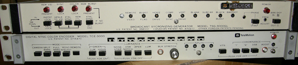
Proffesional NTSC sync generator and NTSC color encoder - Could it get any simpler? As luck would have it, these two items have been consuming space in my storage unit for some time now. It is time for them to pay their rent. The top box is the NTSC sync pulse generator. This box puts out every pulse required for driving the deflection and blanking of the CRT. It also produces the sync, blanking and subcarrier signals for the encoder too. The lower box takes in sync pulses with the RGB video produced by the photo multiplier tubes and encodes it all into a single composite video signal. This would be 80% of the project if I did not have this unit. Additional bonus! The sync generator will genock to an external reference source. This allows for it to be used with a video switcher and effects gerneator. Should I choose. This project is going to be very large. So, it will broken into three parts. The first part, called the projector, contains the CRT, it's support electronics, power supplies and projection lens. Part two, called the color sensor, contains the 35mm slide holder, color separating optics and the photomultiplier tubes. Part three is the sync generator and color encoder stack. The projector and color sensor units will be physically connected during operation. But, can be separated for transportation and storage. AS ALWAYS, STAY TUNED! REFERENCE DOCUMENTS:
1. IEEE: INTEGRATED FLYING-SPOT COLOR SLIDE SCANNER AND TELEVISION RECEIVER 2. United States Patent 3,787,750 Flying spot scanner system high voltage and horizontal deflection circuitry 3. United States Patent 3,527,884 Demountable system for flying spot scanner. (This covers the actual CRT assembly in my possession) 4. [SAMS Publishing ] / SAMS Photofacts folder #1021-2, [Item #176632] Service literature for the Sylvania color television and slide scanner "Home Theater". 5. [RCA 5819 mulitplier phototube ] datasheet. 1949 6. [RCA 6217 mulitplier phototube ] datasheet. 1952 [HOME] [ELECTRONICS PROJECTS] Created: October 11,2014 Last updated: June 28, 2015 |