|
LabGuy's World: Electrostatic Cathode Ray Tube Project 1
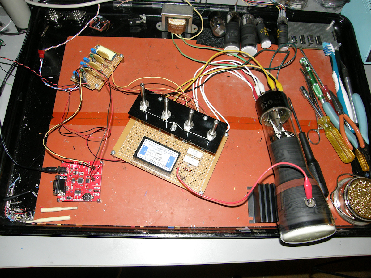
Project Start - 20141030 PROJECT GOAL: Display television pictures on a small oscilloscope or radar display tube with my Tiny TV Mark 2 video rasterizer board. We will accomplish this using a three board CRT driver circuit designed by my friend Eric Schlaepfer. I had assembled his CRT driver boards several months ago. They have been awaiting the arrival of the fully debugged Tiny TV board. Adding a scope clock board kit is in the plans as well! So, let's go! 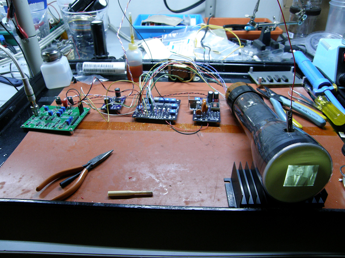
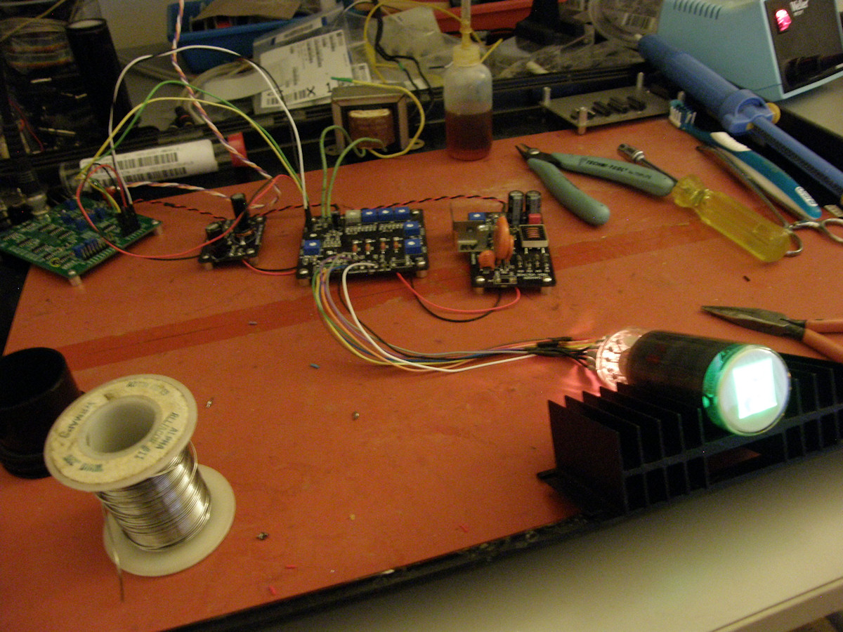
Tiny TV Mark 2 and Eric's 3 boards driving a 3JP7 radar display tube - 20141212 The main distinction of this project is that the tube uses electrostatic deflection. The electron beam is passed between two parallel metal plates that are charged to a particular voltage. If both plates are at zero volts, the beam passes between them uneffected. When one plate is driven more positive than the other, the beam will be attracted to the more postively charged plate and repelled by the negative plate. The deflection plates, and other elements within the tube, operate at and require very high driving voltages. Thousands of volts in many cases. The function of Eric's boards is to convert low voltage drive from Tiny TV to the extremely high voltages required by these cathode ray tubes. 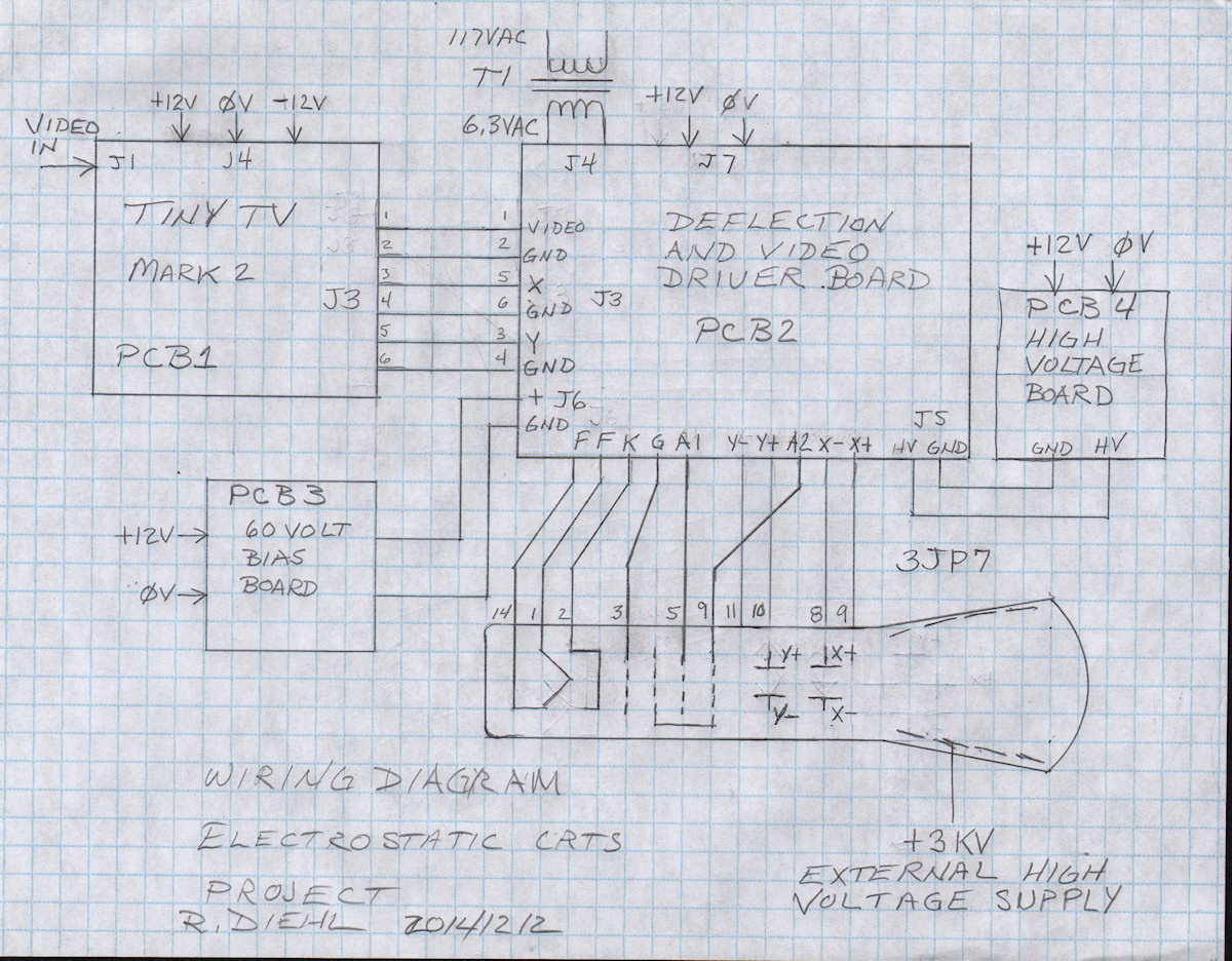
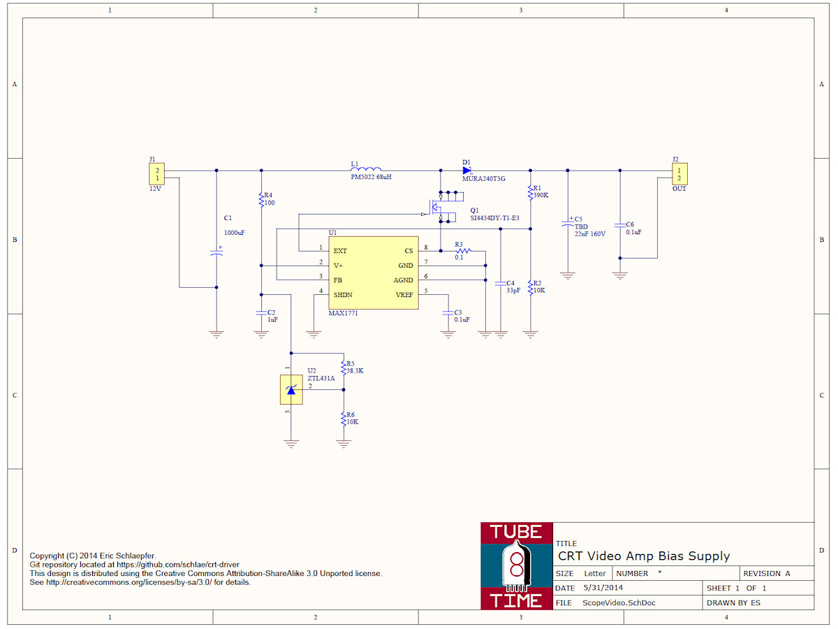
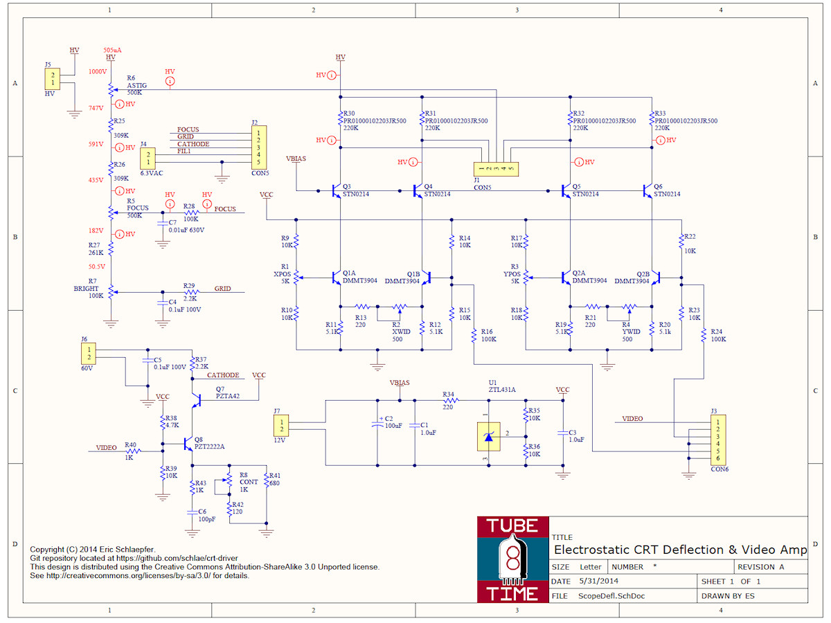
Circuit Schematic - 20141212 The Tiny TV Mark 2, PCB1, provides buffered, gamma corrected, video to Eric's CRT driver boards. It also creates two scanning ramp voltages, in sync with the video, for horizontal and vertical scanning. These are also sent to PCB2 via J3. Horizontal, vertical and video drive are known as X, Y and Z signals when discussing graphic or oscilloscope displays.
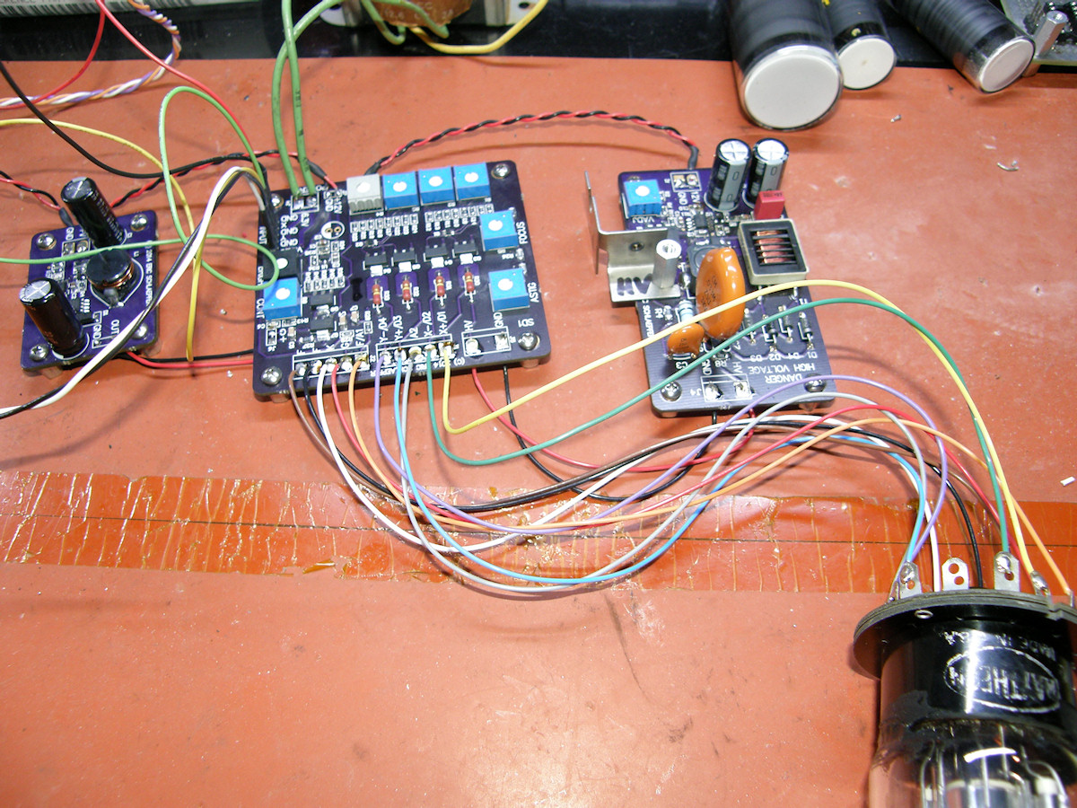
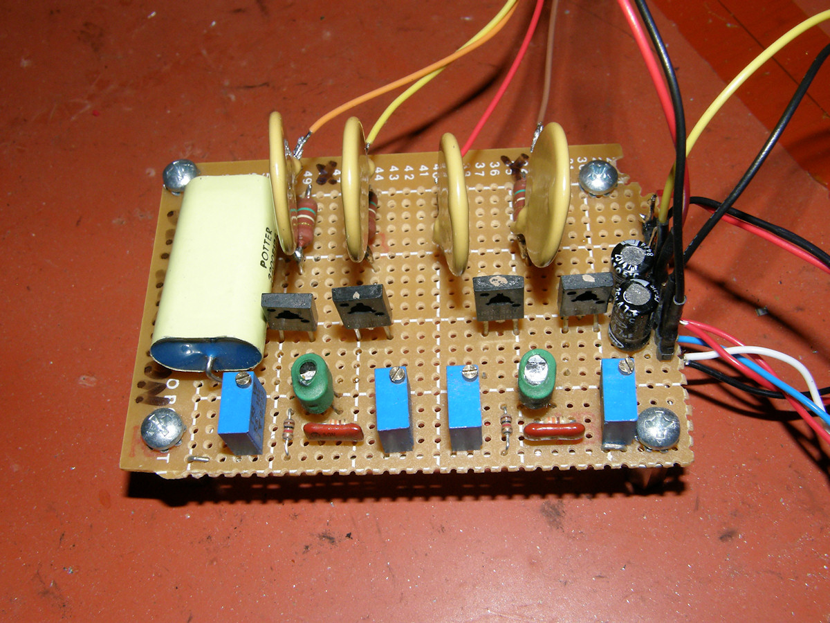
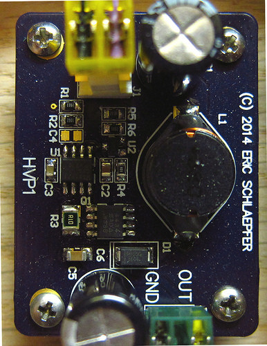
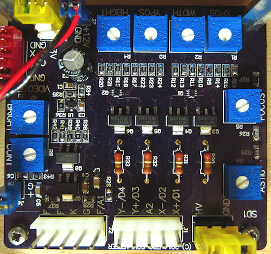
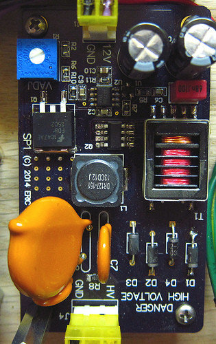
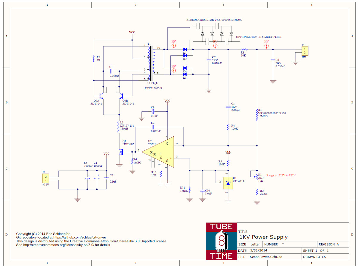
First photo: 60 Volt Bias Board, PCB3. Converts +12 volts to +60 volts for the CRT cathode driving video amplifier. Second photo: Deflection and Video Driver Board, PCB2. This board runs on four power supplies. They are; 6.3 V for the tube heater, +12VDC for low voltage circuits, +60VDC for the video amplifier and up to +1,200VDC for CRT second anode and deflection plate driver amplifiers. Then the board provides all of the DC levels and other appropriate driving voltage to the CRT. A generous array of potenetiometers allows for very flexible set up so that it can support the greatest number of CRTs. Last photo: 1,200 Volt High Voltage Power Supply. Steps 12 volts up to +800 to +1200 volts at several milliamps. Voltage is set with potentiometer. Work around this board with great care. 
3,000 volt external power supply for the post deflection anode - 20141212 Here we see my plus and minus 3,000 volt bench power supply. I use this for when a CRT is equipped with a PDA or Post Deflection Anode. This is a conductive coating on the inside of the CRT between the deflection plates and the screen phosphor. This way, low velocity electrons pass between the deflection plates and are deflected more than fast electrons. After passing the plates, the electrons are now influenced by the PDA electrode and accellerated to the phosphor. This gives high deflection gain along with higher brightness than a tube lacking this feature. 
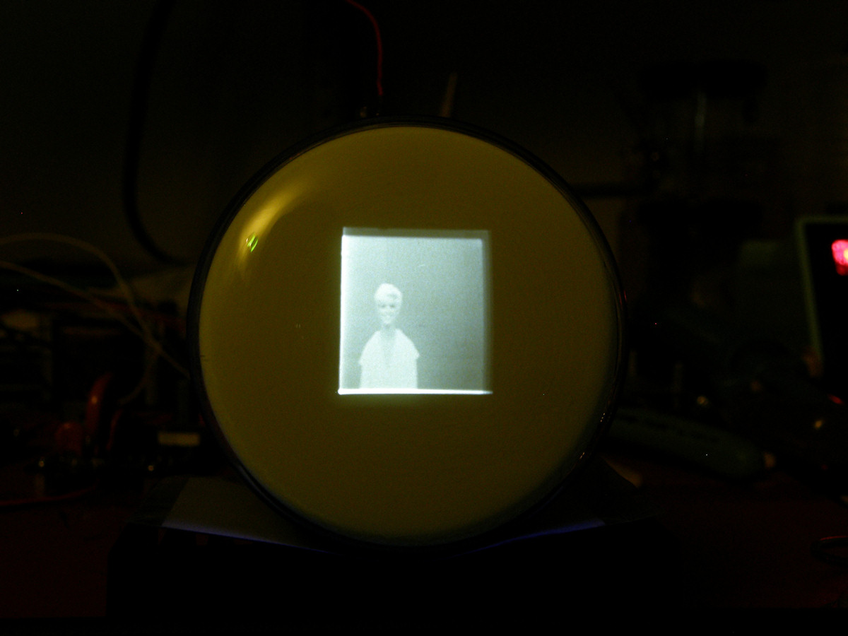
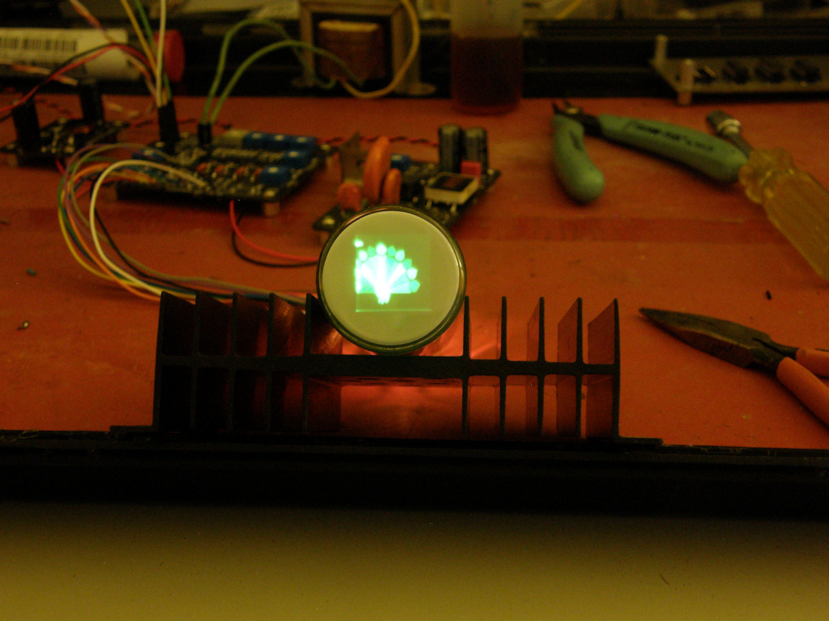
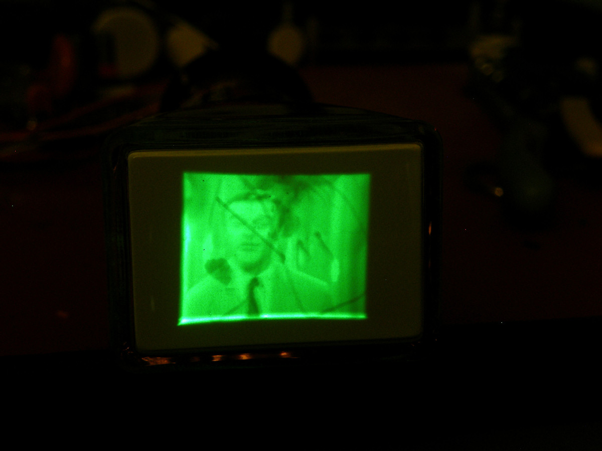
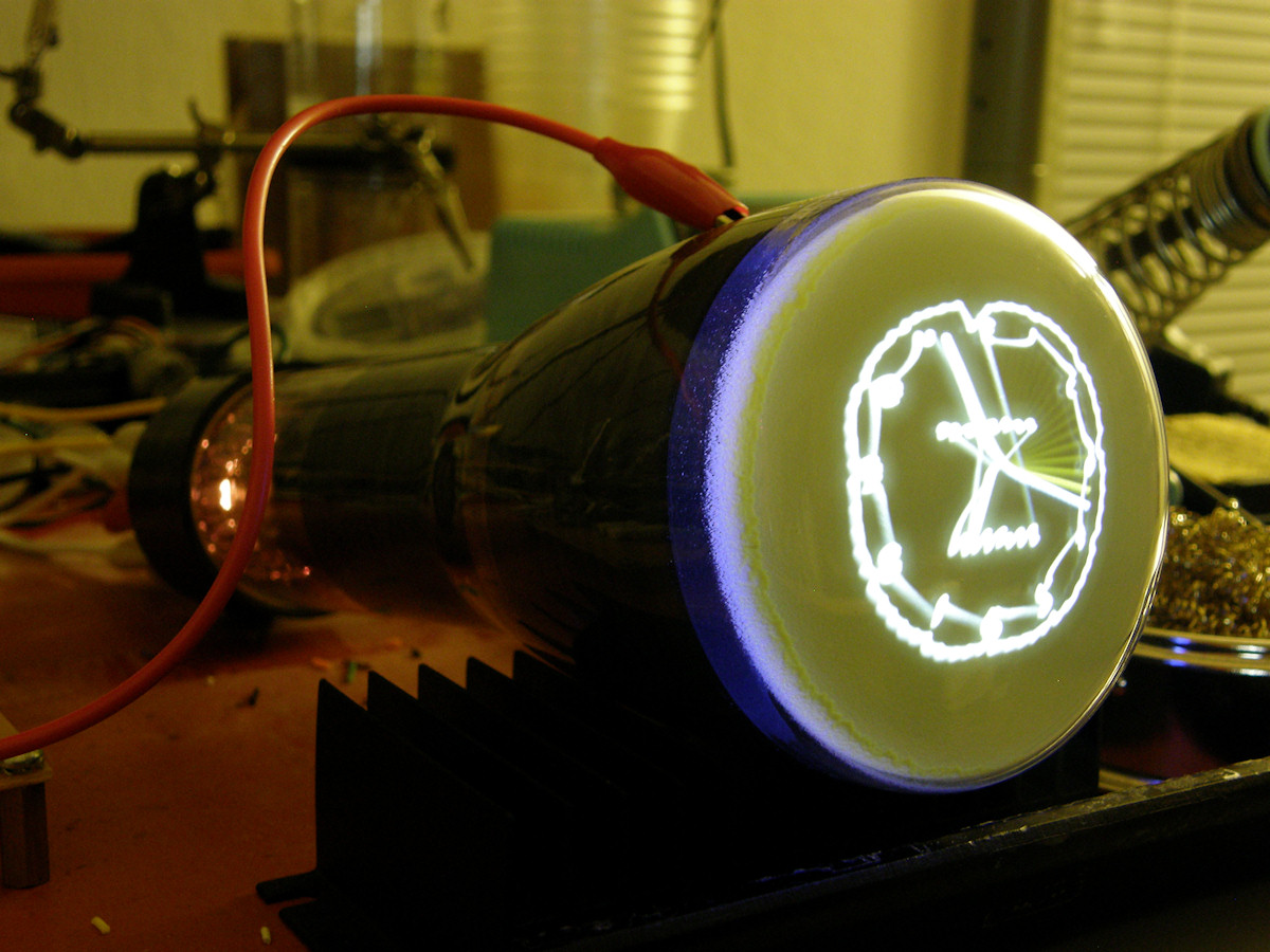
3JP7 screen shots - 20141212 So, here we go. Fired up the boards. No smoke. Tweaked the pots until I got the best image possible. Began debugging the problem visible in the photos when my Tektronics TDS744A oscilloscope died. Dead as a door nail! No scope, no more troubleshooting this weekend. Looking at the pictures above, there is an obvious problem with the horizontal scan on the left side. Before the scope died, I was able to prove to myself that the Tiny TV board was putting out three good signals at about 3 volts amplitude. I probably missed an update somewhere on Eric's page. Will investigate that next time I sit down to the project. Obviously, this is now on hold. Let's discuss P7 radar phosphor. P7 is a two stage phosphor. A long persistance yellow phosphor with a very short persistance blue/ultraviolet phosphor deposited on top. The electron beam does not have a strong effect on the yellow phosphor. The yellow phosphor is, instead, excited brightly by ultraviolet light. The yellow phosphor's second desirable property is that it glows for a usable period time after stimulus is removed. Up to 30 seconds in a darkened room. This long persistance was used effectively as an image storage memory in the earliest days of analog radar and before computer memory was plentiful and cheap. If one wishes to view the long persistance effect of P7, a yellow filter can be placed over the tube to block the blue light. Conversely, if one wishes to view, and perhaps photograph, the blue phosphor, a blue filter is used. 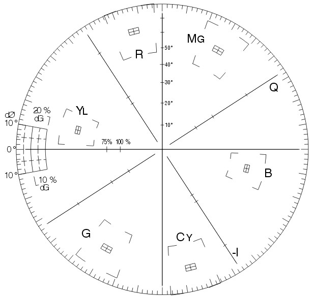
Video Vectorscope Display - the color signal analyzer - 20141213 Image Source Credit: Wikipedia The scale above represents the relationship between the color difference signals in composite video. The vertical axis is R-Y and the horizontal axis is B-Y. I chose this example as it shows the primary colors and their inverse evil twins. Additive and subtractive primary colors. Note the color boxes on the vectorscope display above. The opposite color of blue is yellow. The other primary colors and their negatives are red/cyan and green/magenta. In fact, many broken NTSC color TVs fail to either a green or magenta picture when the color decoders malfunction. In the case of a black and white video signal, the vectorscope displays a dot at the center - no chroma info, only lumanance. In this view of the video signal, the luminance is the vector going straight into and out of the screen at the center of the scale. To read more about that at Wikipedia, click the link below the image. I present this to you to visualize the color relationships. To summarize, the P7 screen images in the photos look grey. They are. This is because both the blue and the yellow light are summing together to produce white light. Or at least as far as the human eye is concerned. It happens that blue and yellow are primary opposites. Blue is an additve primary while yellow is a subtractive primary color. When two primary opposite colors are mixed, the hues cancel out and only the luminance, or brightness information, remains. Hence, the appearance of grey scale. This is only valid for still images on P7. Moving images have the most annoying yellow comet tails and blinding bright blue edges. Not good for TV viewing. Perfect for radar. 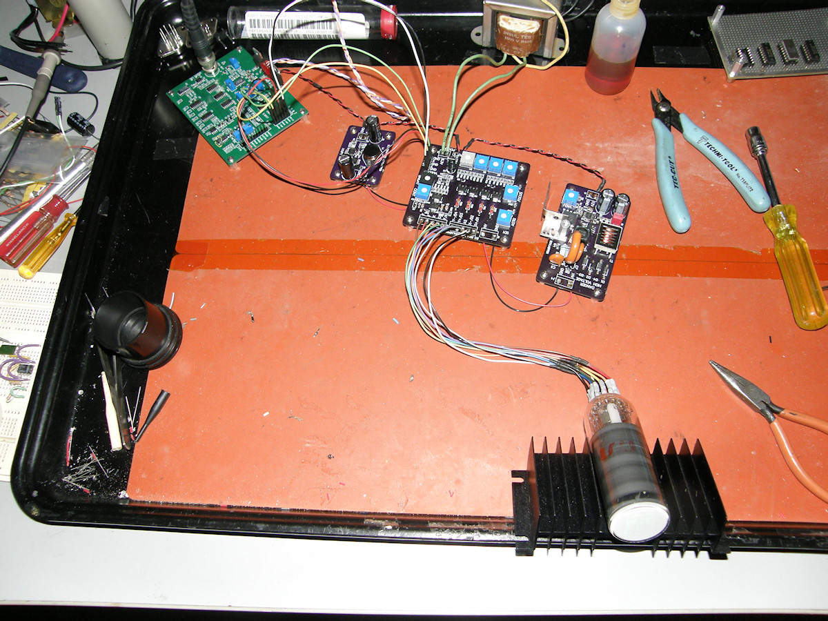

1EP1 screen shots - 20141213 Hooked up the 1EP1 CRT to Eric's boards. Turned the high voltage down to 800 volts and it worked just fine. Not good for a TV as the beam spot is too large even when focused as well as possible. Still pretty impressive. 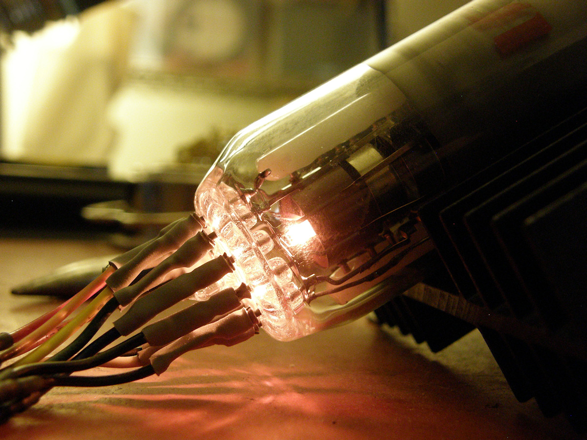
Glow, baby, glow! (1EP1 heater) - 20141213 

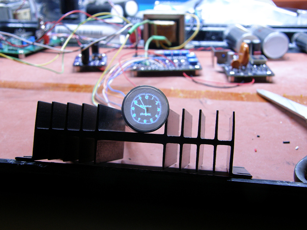
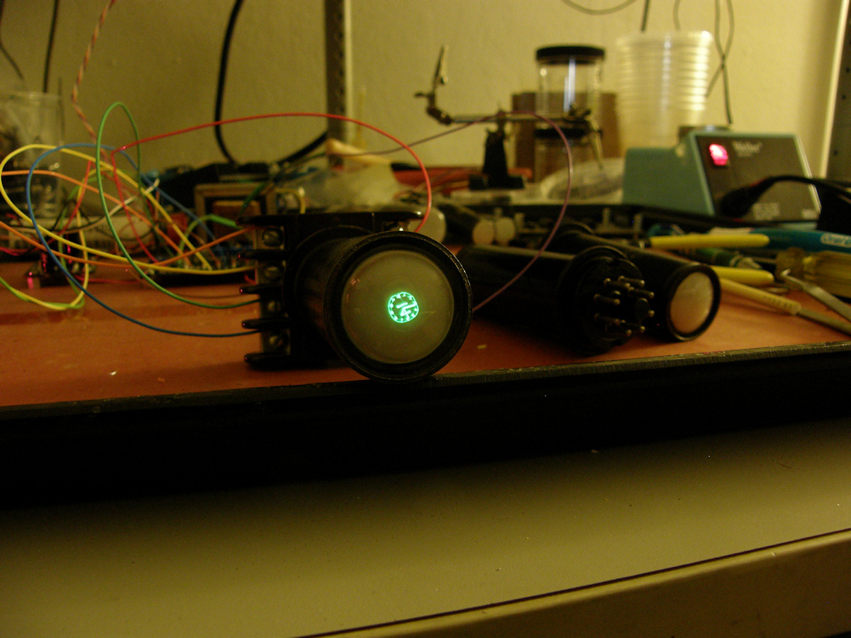
SparkFun O-Clock, AVR Oscilloscope clock kit and Labguy's various CRTs - 20141216 In the first photo we see the [Sparkfun AVR Scope Clock] kit, on the left. In the background are the high voltage driver boards and in front of those is my 1EP11 blue phosphor CRT. The second photo is the same set up with my green phosphor 1EP1. Pictures 3 and 4 are of the scope clock output as it was inteded, driving a high bandwidth XYZ display. In this case, my Tektronics 606B. Eric's high voltage driver boards have less bandwidth in their amplifiers. This accounts for the visible distortions on the smaller tubes. The next CRT I tried was the 1DP1. However, Eric's board does not necessarily support CRTs that have one pin shared by one side of the heater and the cathode. I placed a jumper on the deflection board from the cathode pin the non-ground side of the heater pin. After that, the board does not light the tube. This is deflection board number two that I have damaged this way now. One left! I'll have to purchase more high voltage transistors from Mouser. Good thing I like to solder! Datasheet for these tubes are references section, at the bottom of this page. 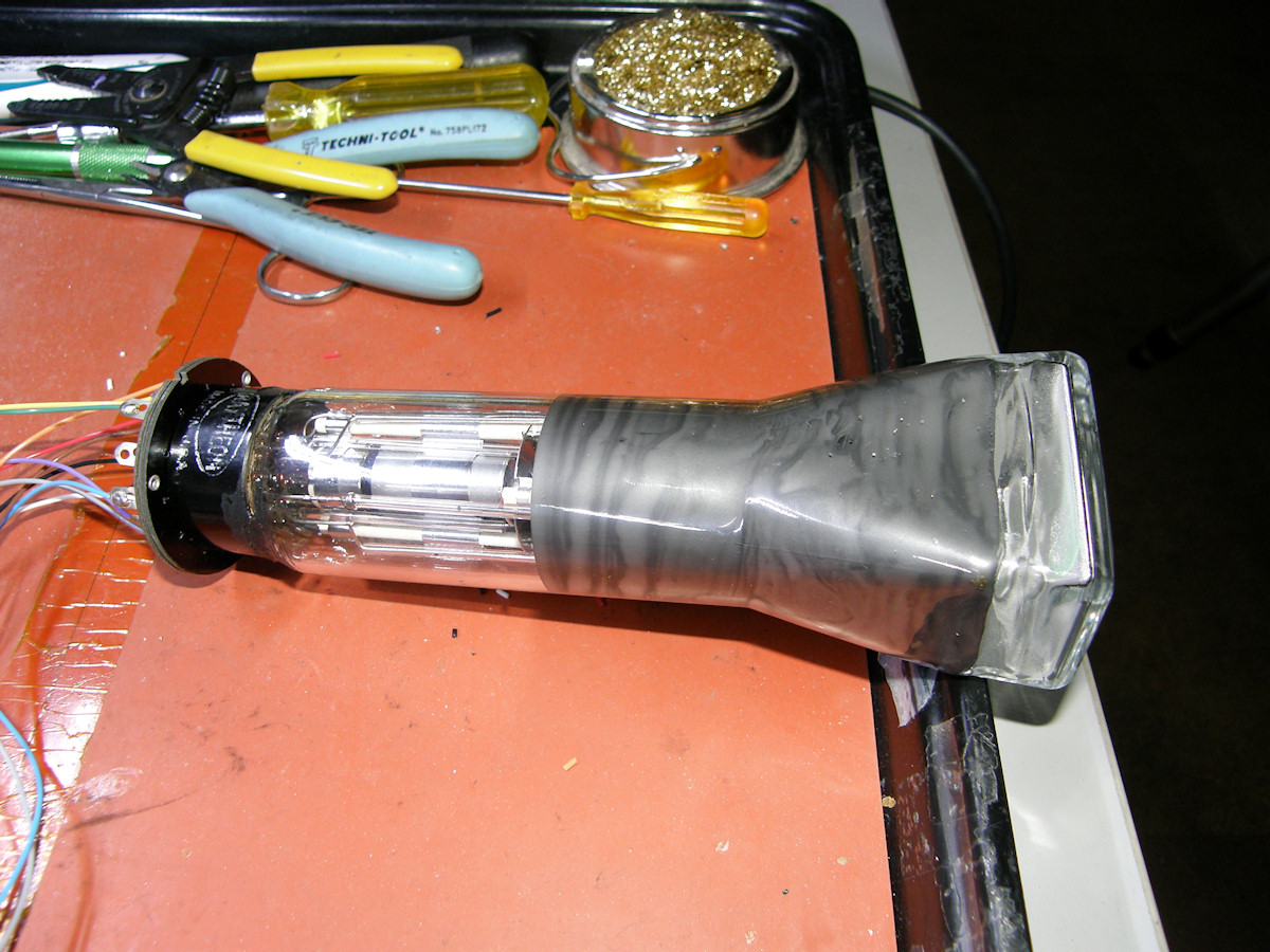
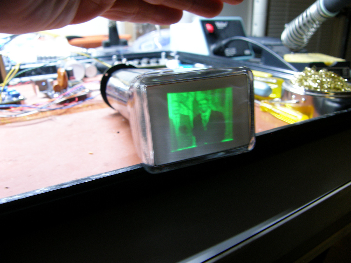
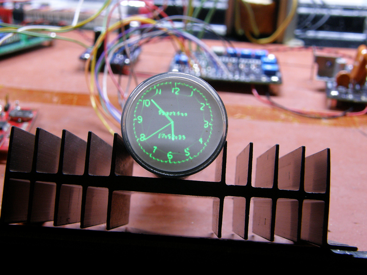
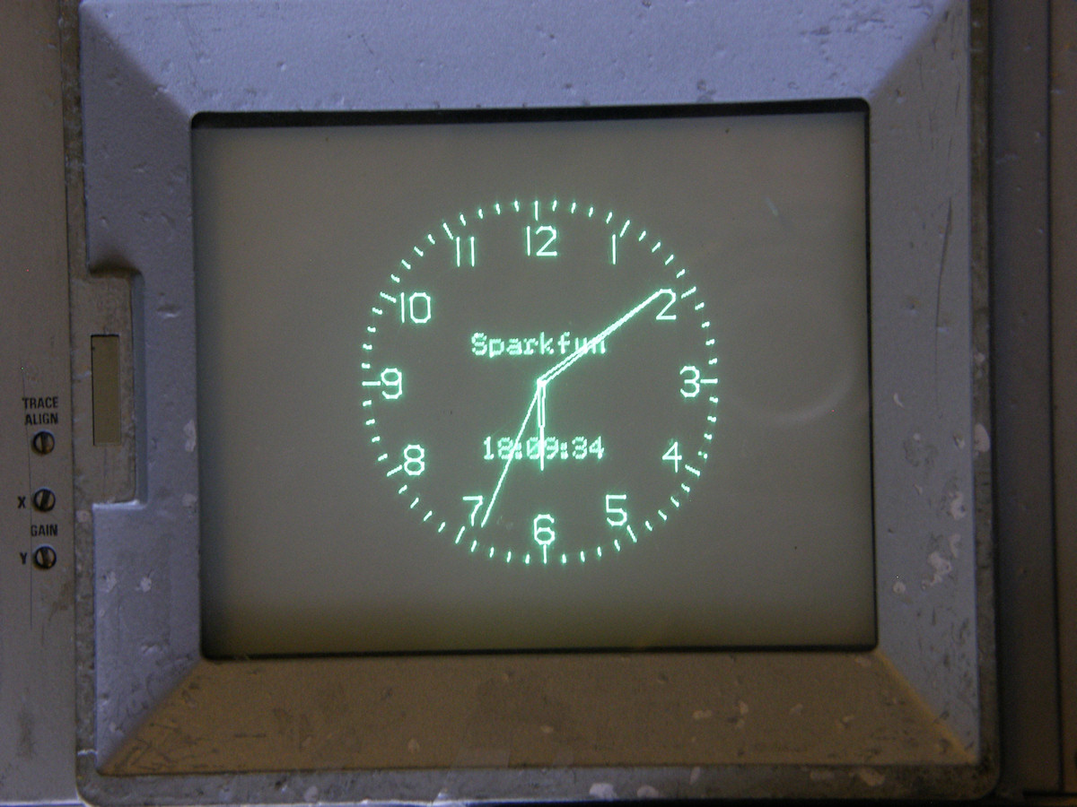
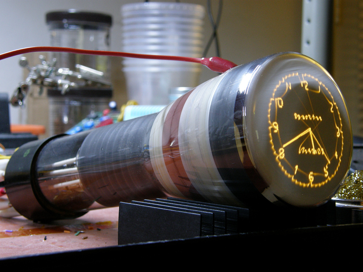
Raytheon 3UP1 2.5 inch rectangular electrostatic CRT- 20141219 The 3UP1 is a compact rectangular oscilloscope CRT circa 1957. As old as Labguy! It is 1-3/8" wide, 1-1/8" high and 7-1/2" long. The gun runs on 2,000 volts. So, it is coasting at 1200 volts here tonight. The higher I set this voltage, the smaller the image becomes. This is normal for these tubes. As A2 voltage increases, electron velocity also increases. Now the electrons spend less time between the deflection plates and so are deflected less than slower electrons. Datasheet for this tube in references section, at the bottom of this page. This tube works extremely well! The picture is nice and sharp with clear details. This 3UP1 is being driven with my Tiny TV rasterizer and Eric's high voltage drivers. Unfortunately, this tube has been sadly abused. There are many distracting burn marks in the phosphor. It might look better with the scope clock.... 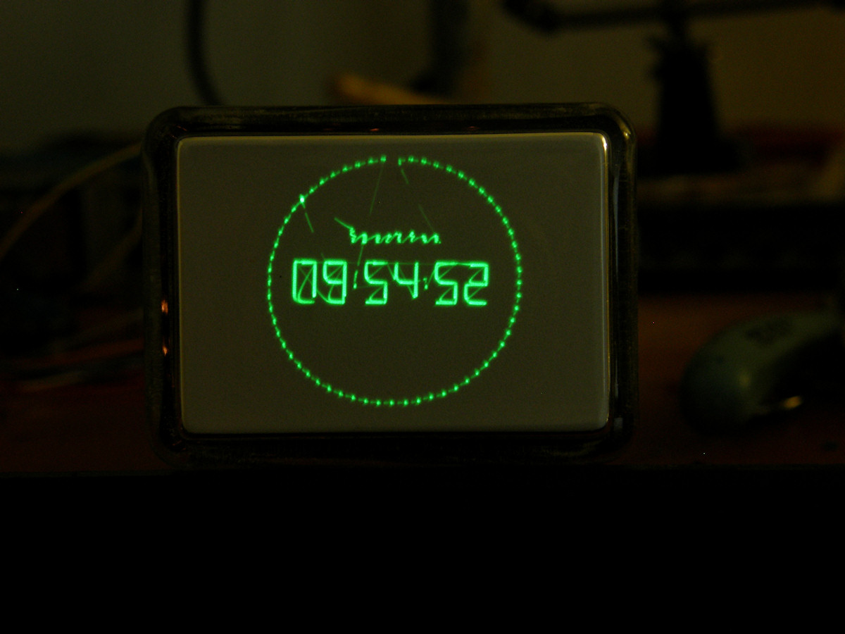
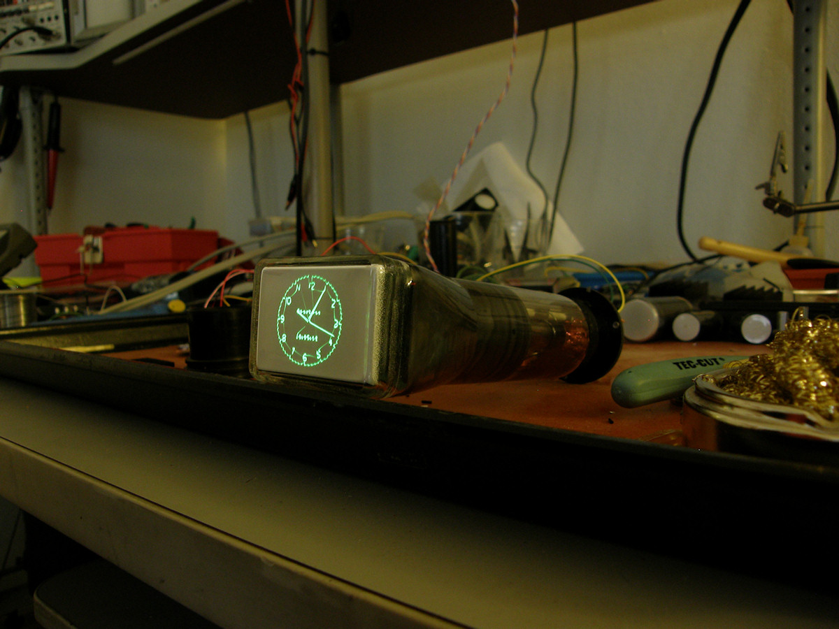
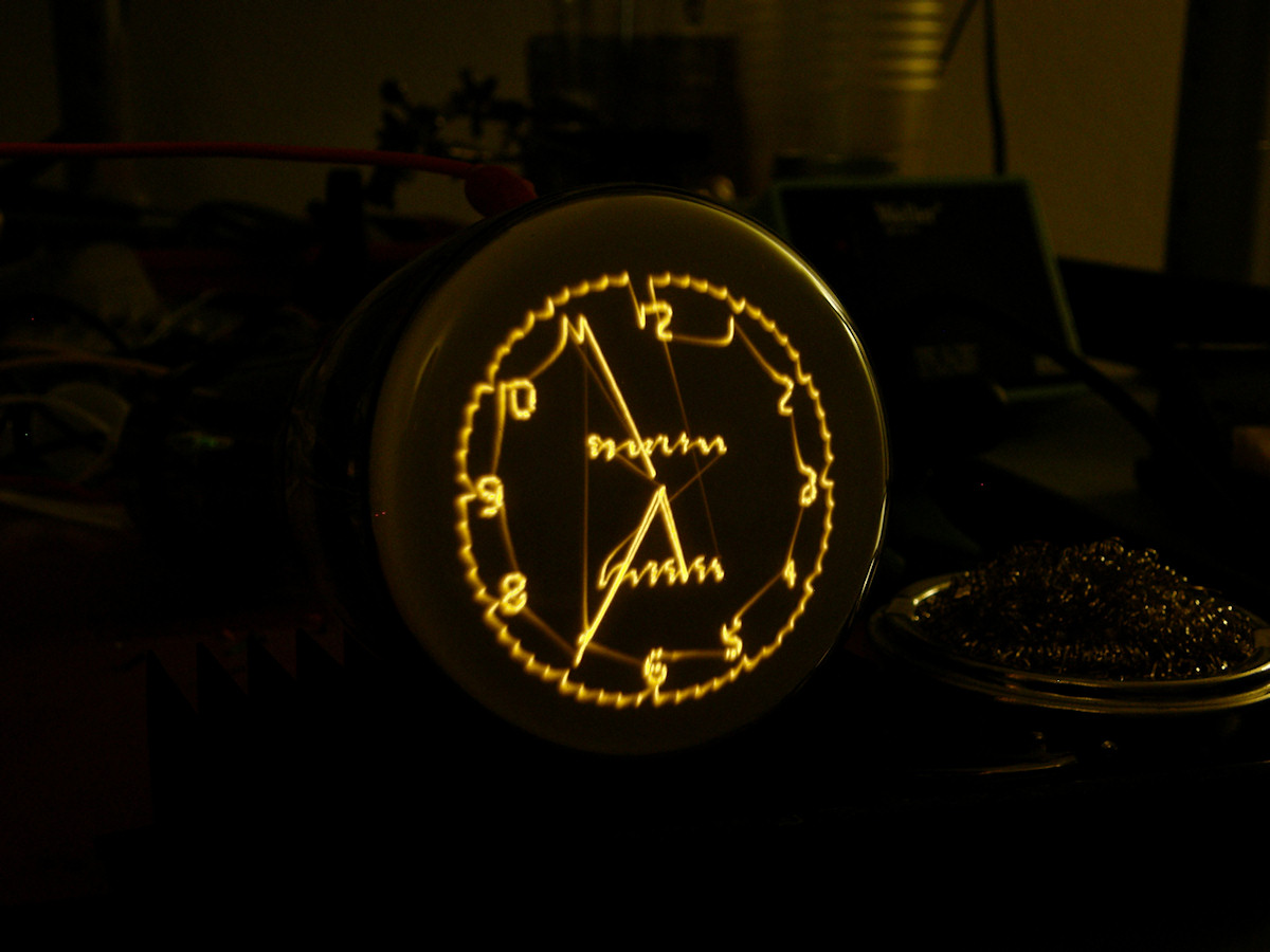
Raytheon 3UP1 with Sparkfun AVR O-Clock Display - 20141220 I quickly wired up the scope clock this morning and tried it with the 3UP1. This display is more acceptable than the TV picture with the burned phosphor. Since this display has no grey scale, to speak of, This 3UP1 is quite usable for vector graphics and general oscillography (oss ill ogg rah fee). It's a shame the phosphor is burned. It would be ideal for 4:3 aspect ratio standard definition video. I was hoping to use this one for my fully adaptive, any standard, television monitor. Datasheet for this tube in references section, at the bottom of this page. 
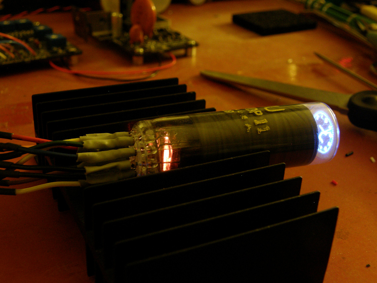
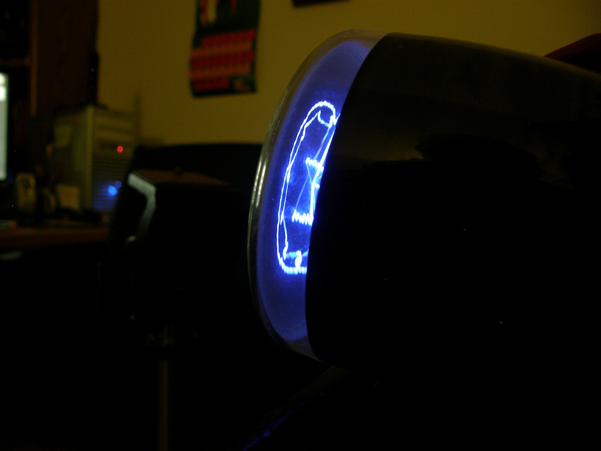
National Union 1DP11 with Sparkfun AVR O-Clock Display - 20141220 The 1DP11 is a cute little tiny tube. Three quarters of an inch in diameter and just two inches long, it's the smallest electrostatic CRT that I am aware of. The screen is the same size as a dime! Check out the eye catching blue color of the P11 phosphor. One of my favorites. You can see the image on the backside of the screen in the last photo. You can also see the radio tube style heater/cathode at the back end of the tube. Datasheet for this tube in references section, at the bottom of this page. I worked out why I was blowing up video output transistors when running CRTs that share one pin between the cathode and one side of the heater. The fix is to not route the 6.3VAC circuit through Eric's deflection board. The path on the deflection board has one side of the transformer grounded. Connecting the cathode output to that circuit looks exactly like connecting the cathode output directly to ground! Bad for the transistors! 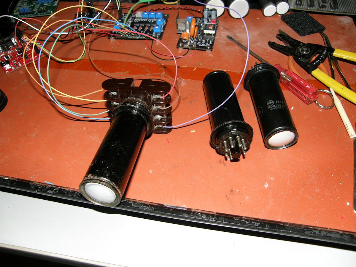
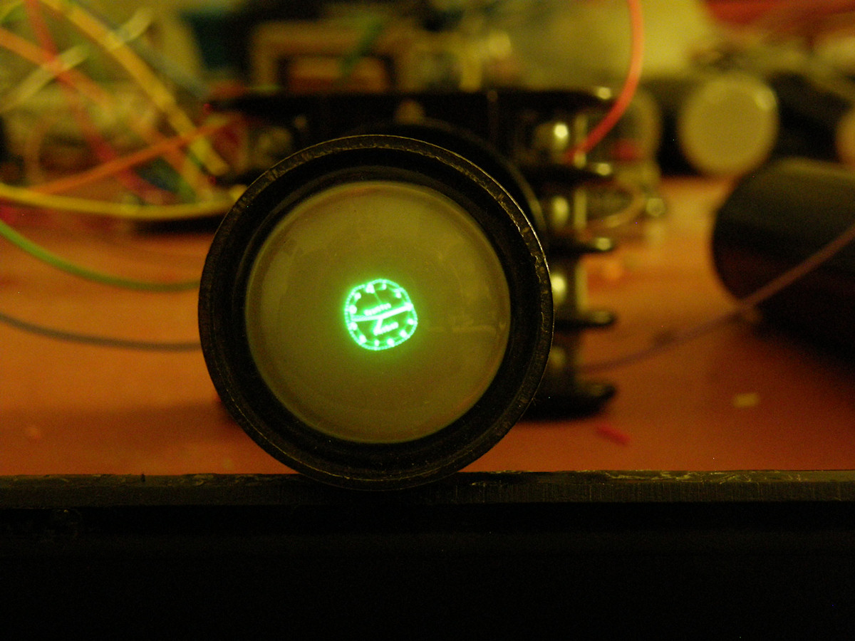
Circa 1937! RCA 913 with Sparkfun AVR O-Clock Display - 20141220 CORRECTION! 20141223. I previously stated that the 913 first appeared in 1927. That is incorrect. RCA introduced the 913 in 1937. This CRT is the oldest type in my collection. RCA started selling these in 1937 so that a low cost oscilloscope could be realized by low budget radio repair shops. Television was not yet available at that time. This is a single ended tube. This means that several electrodes share pins. Anode #2 and two of the deflection plates are tied common and routed to pin 1. It is no help that the outer can serves as the shield and is tied common with the second anode. The outside of the can is sitting at 800 volts. Yikes! Don't touch when it is operating. Datasheet for this tube in references section, at the bottom of this page. Single ended deflection. This means that a deflection waveform is sent to only one deflection plate of the pair. The alternate plate is held at a steady DC voltage, usually equal to the A2 voltage. This process works. But as you can see, for a given deflection voltage, the tube gives half the deflection range. In the bipolar drive, one plate goes up 1 volt the other down by 1 volt. Total voltage between them is two volts of change. Compare the following schematic diagram with the one shown earlier and you can see the difference. The 913 has the most shared pins of any CRT I've used so far. The HK (heater/cathode) pin and the D1/D3/A2 shared pin. This saved RCA the cost of four additional pins and larger tube envelope, making the 913 very economical to produce and sell. The 913 pins out to a total of 7 pins with one do not connect factory test pin - pin 8. I think pin 8 may be the getter pin. The getter is an internal tube element that is used once right after the tube is sealed to consume the last remaing traces of oxygen within. A chemcial cocktail is deposited on the getter electrode and fired with high voltage. It vaporizes to absorb gasses. That's the shiny silver spot you see on the inside of glass vacuum tubes. If that spot is bright and shiny, the tube is air tight. If it is powdery white, the tube has lost its seal. You can't see inside a 913. (I was hoping one of my 913s was bad so we could dissect it. I won't scrap an operational vacuum tube!) 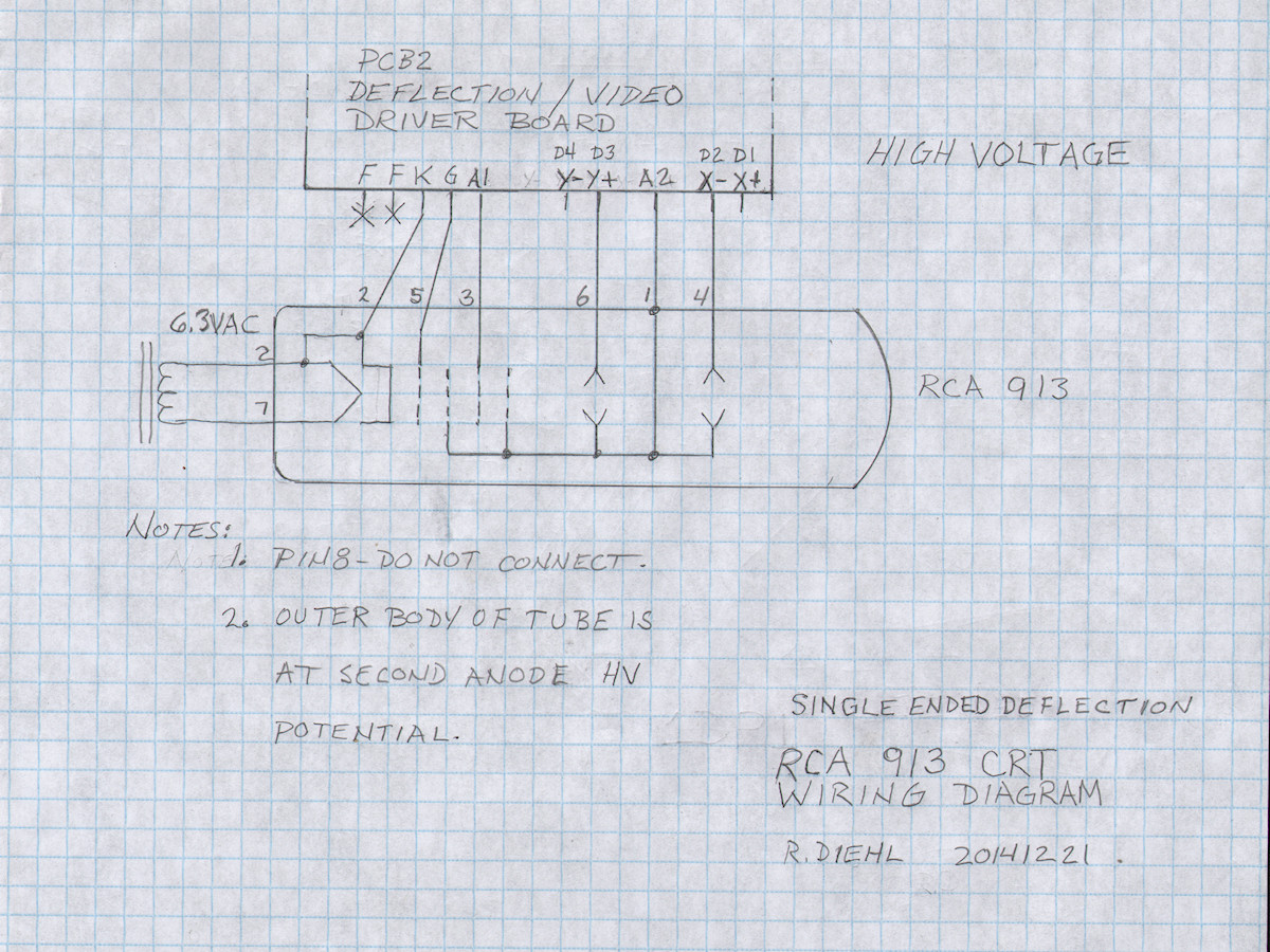
RCA 913 wiring diagram for use with Eric's CRT board driver set - 20141221 Note that the 913 has the cathode sharing pin 2 with one side of the heater. See how I bypassed the deflection board and floated the heater element from ground. The transformer and wiring add a lot of stray capacitance and can effect drive bandwidth. This results in a loss of detail, or blurring, of the screen image. This heater cathode wiring is the same for the 1DP1/1DP11 tubes as well. Normally, this kind of CRT is operated with the cathode at a negative high voltage. The outer can and second anode are grounded, providing free shielding of the tube. Now, the two lone deflection plates can operate near ground potential. Their average DC level must be equal to the second anode. Eric's board runs the second anode at high voltage and centers the deflecting voltages around this voltage. Running the anode at high voltage and the plates at low voltage will unfocus the beam due to interaction between the plates and anode. This is why the plates and second anode should all be at the same "average" voltage. Fortunately, the Astigmatism control on Eric's board allows precisely for this. To set Astigmatism, I set both X and Y centering controls to their midpoint settings. Then adjusted the Astigmatism control until the image was in the center of the tube. Now all deflection plates are at the same average voltage! A light touch up of the Focus control and the clock image was as sharp as it was going to get. In single ended scanning, the Astigmatism Control acts as the Diagonal Control by virtue of being tied to two of the deflection plates! That made me giggle for several moments after seeing it for the first time. Diagonal Centering? Now, that is silly! I tested all three of my RCA 913s with this setup. They are all bright and sharply focused. Not bad after as much as 77 years! I have no idea how old my particular tubes might be. RCA manufactured 913s well into the 1950s. Possibly the 1960s. Please enjoy this fourteen minute video of these tiny CRTs in actual operation - 20141222 CORRECTION! 20141223. RCA introduced the 913 in 1937. In the video, I state that the 913 first appeared in 1927. That is incorrect. 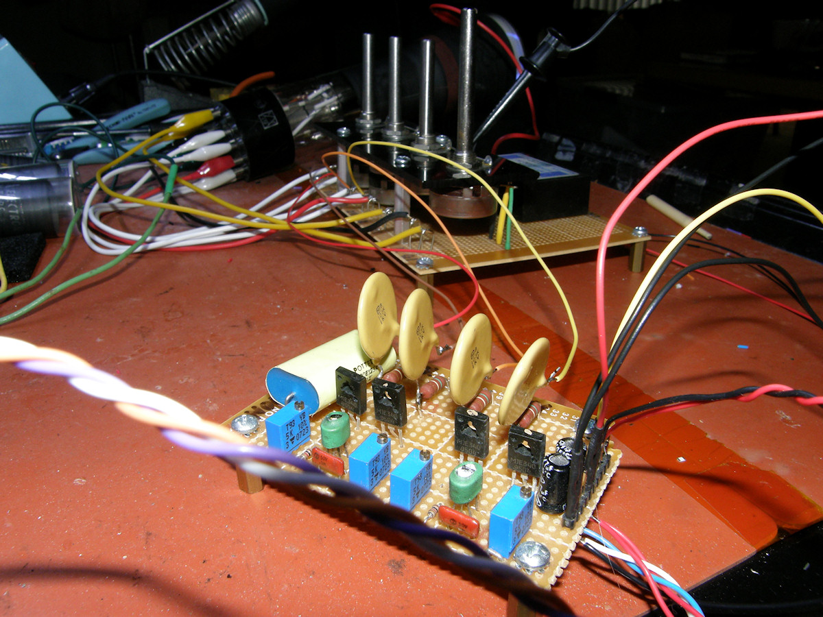
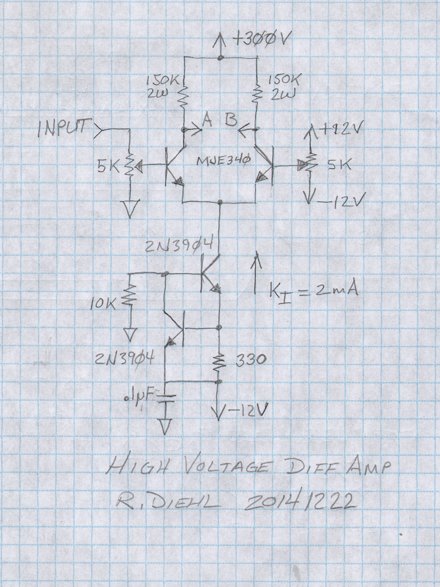
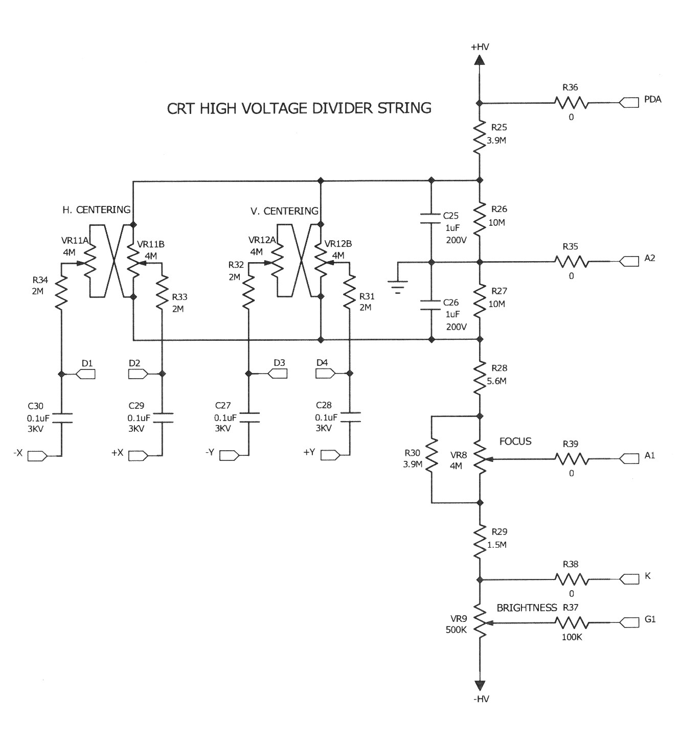
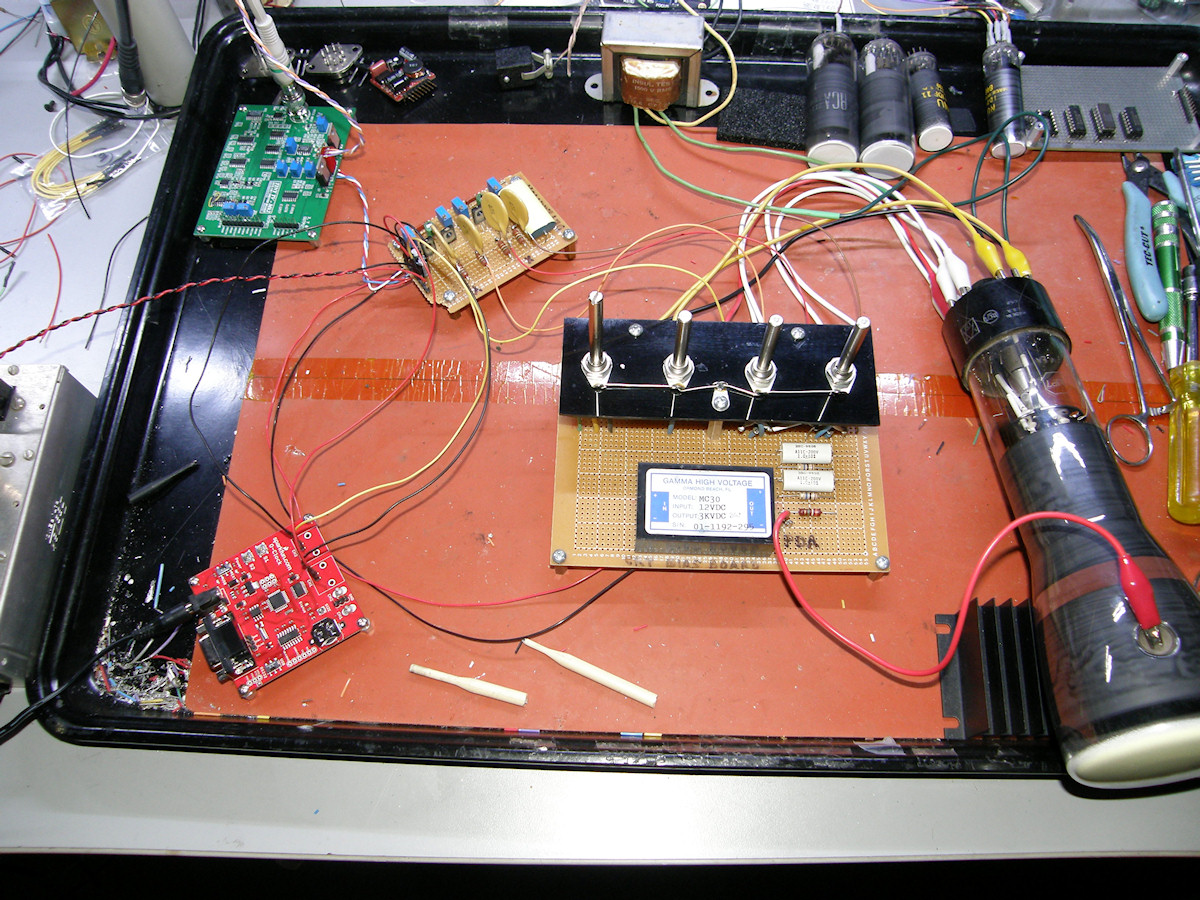
Schematic of CRT voltage divider and HV Differential Amplifier - 20141222 Dug out a deflection board I built several years ago and never got around to testing. Points A & B, in the first schematic connect to the points marked -X/+X or -Y/+Y on the second schematic. Now the operating DC voltage of the high voltage amplifiers will not cause an astigmatism issue in the CRT. Each collector can swing from 0 volts to 300 volts. With the two outputs operating 180 degrees out of phase, the deflection plates receive up to 300 volts peak to peak. More than enough to overscan any tube. The outputs of the amplifier are AC coupled to the deflection plates as shown in the second schematic. In this design, the second anode of the tube operates at zero volts, or ground potential, and the cathode is operating at -1,980 volts. The post deflection anode is operating at +910 volts, include the approximately 100 volts dropped across the brightness pot and the total supply voltage adds up to 3,000 volts absolute. This high voltage is provided by a [Gamma High Voltage model MC30], a 3,000 volt, 1mA (3 watt) power supply. Have some masochistic fun today. Sharpen your number two pencil and grab your abacus. I said ABACUS! Then calculate the values for the voltage divider string above. Assume the HV power supply is 3,000 volts. Ready? Begin! The centering controls consist of dual pots. By way of their wiring in the divider chain, these pots have 200 volts, or more precisely, plus and minus 100 volts across them. They are wired such that one pot increases output while its mate decreases. When centered, the pot/pairs output just about zero volts between them. Look at the structure of the divider. See how the center of the positioning pots is centered on the voltage divider tap chosen as the divider's ground reference. The deflection voltage is AC coupled to the plates via the four .1uF 3KV capacitors. Their DC reference is established by the centering pots. And the AC coupled signal automatically swings plus and minus of this DC reference. 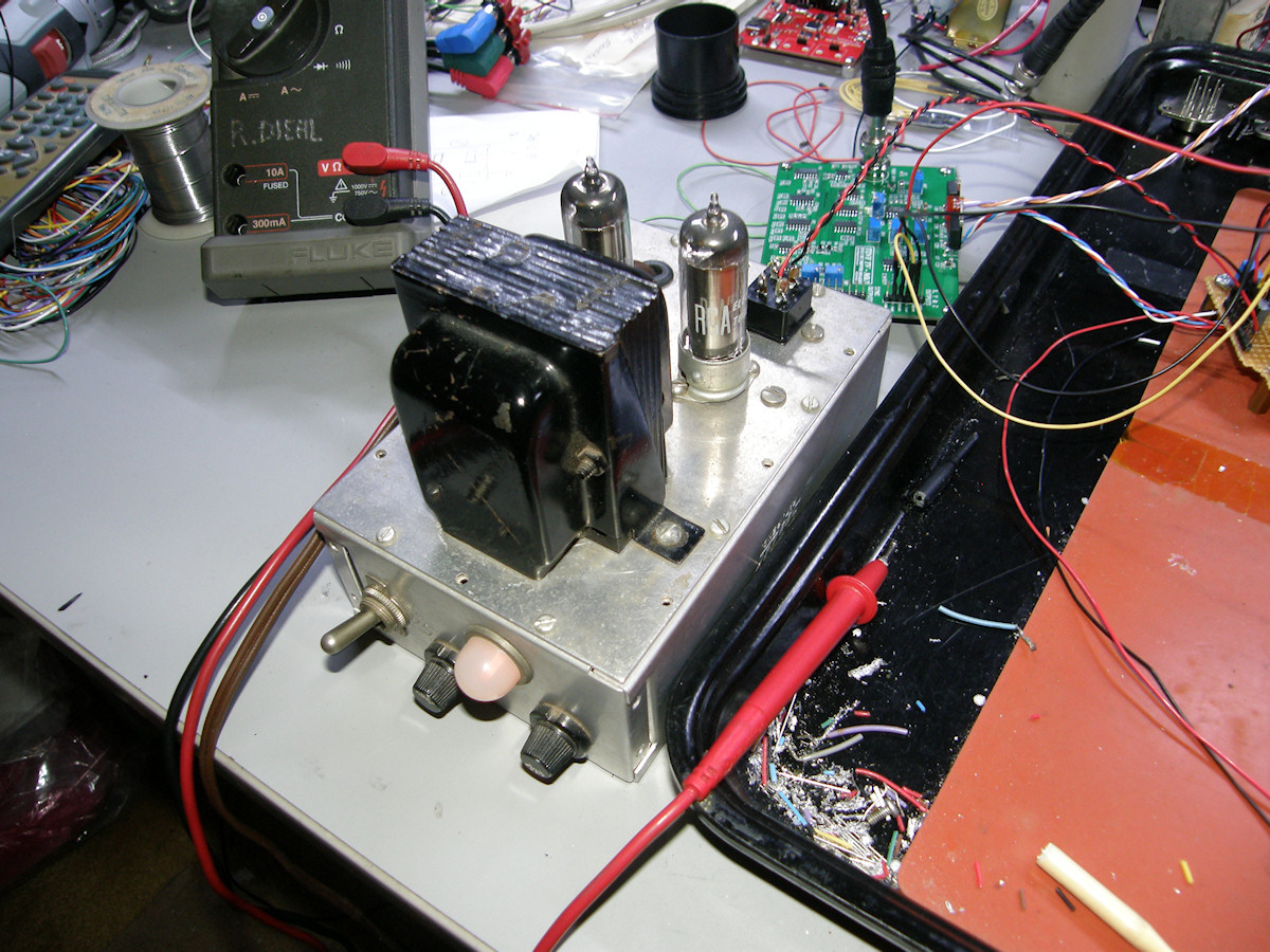
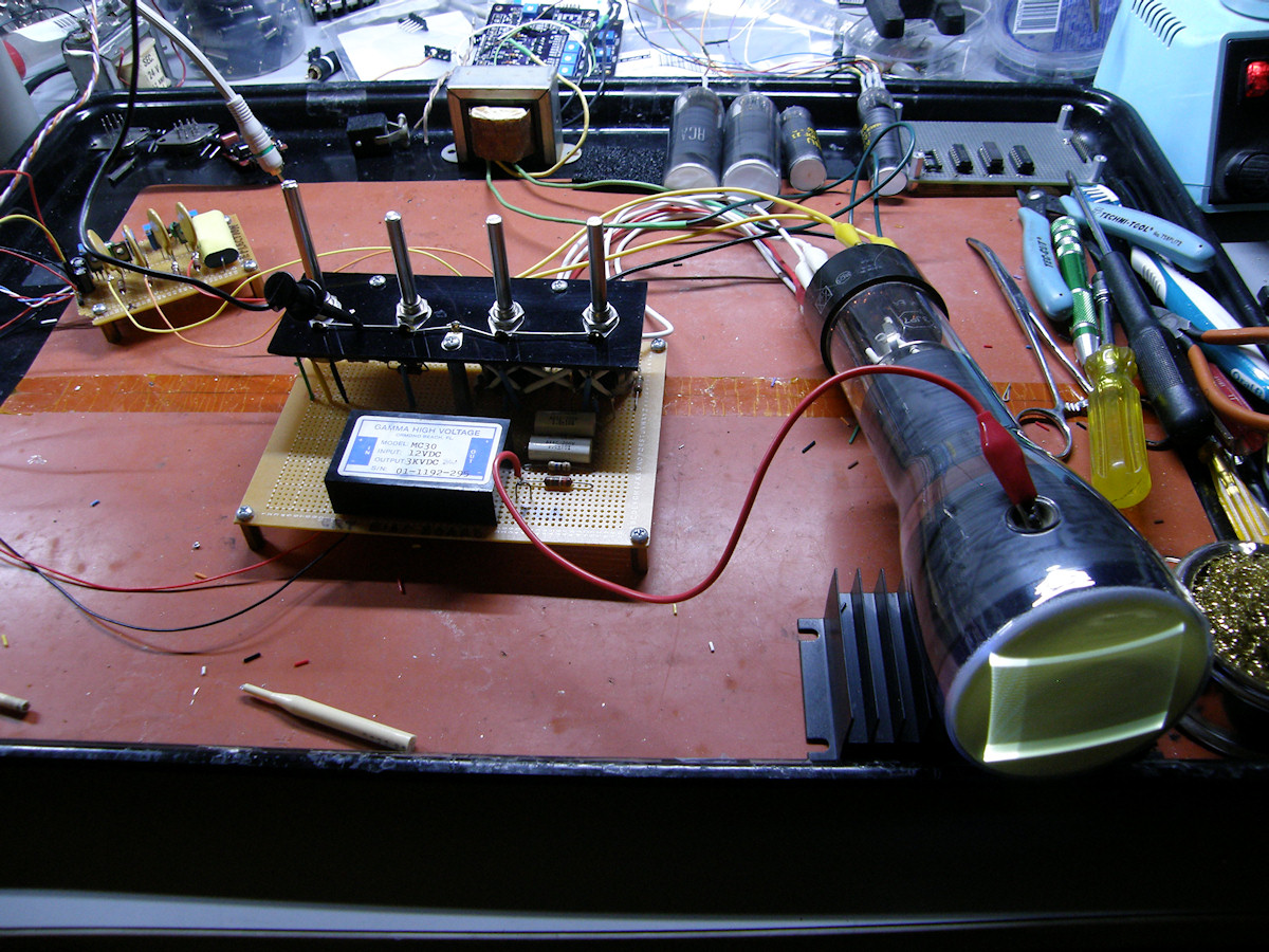
Labguy's prototype Deflection board and antique 300V regulated power supply - 20141222 First photo is of my antique home brew 300 volt regulated power supply. It puts out 6.3 VAC / 1 Amp, +340 volts unregulated and regulated +300 volts. Regulation is provided by two type 0A2 [150V voltage regulator tubes]. Based on the age of the parts, a competent hobbyist built this power supply some time in the mid to late 1950s. I base this on the presence of [selenium rectifiers] instead of silicon. It still works great after more than 50 years. It is providing regulated +300 volts for my dual deflection amplifier board. Second photo. The dual deflection amplifer is the small brown board in the upper left. It is being driven, in this case, with the SparkFun scope clock board. That did not initially work correctly, so I switched to the Tiny TV 2 board for its more repetative scanning ramp. Last photo, The deflection ramp voltages are excessively amplifed and severely clipped. You can see that this board is able to scan a larger area than the previous Tubetime boards. The AC coupling means my scan amplifiers can operate over the full 300 volt range and the CRT can operate at any voltage it may require. At this time, I don't have a video amplifier of my own design. But, gears are grinding... Which leads us to.... My Tektronics TDS744A digital oscilloscope is still in the shop. No word as of yet on when I can expect it back or what it will cost. Troubleshooting these projects is a lot easier with my scope. I have enough parts on hand to build a relatively fair oscilloscope. But, you need a working calibrated oscilloscope to debug and align the new one.... OH! The irony. 

SUCCESS! My high voltage scan amplifer is finally working - Sort of! - 20141223 Persistence pays off. The problem is that the gain of the X & Y amplifers is extremely high. Without my oscilloscope, I can't be certain about anything. But, it appears that the output level controls on both scope clock and Tiny TV 2 are set almost to zero. The same for the input level controls on the high voltage deflection board. But with careful tweaking, I was able to get the scope clock to appear on the screen. I then switched the amplifier inputs back to the tiny TV board and tweaked its X & Y output levels to get the fair looking TV raster in the last photo. Observed that the scan fold over distortion appears to be gone. I suspect that the horizontal sawtooth wave is coming out as a sine wave and may be masking that problem. Or not. The bright line across the top of the raster is the vertical ramp generator reaching full amplitude and clipping before the end of the scan time. Need to add about 1uF from the vertical ramp generating capacitor. Or lower the constant current value slightly. But, that is not a show stopper. Even if the scan is upside down. Twenty seconds with the soldering iron, swapping the deflection plate leads will flip that the right way around. The next step will be to add video drive input to the CRT high voltage bias board. Then we can feed cross hatch pattern to see the high voltage X & Y amplifier linearity directly on the screen. So, in the mean time, enjoy the two center photos that show off the P7 phosphor in all its glory. Long persistance yellow phosphor on the front, short persistance ultraviolet/blue phosphor on the back side. 

MORE SUCCESS! My high voltage scan amplifier is finally working correctly! - 20141223 After a careful analysis of the amplifier design, I realized that I'd forgotten to add the emitter degeneration resistors to the two MJE340 transistors. These resistors, R3 and R4, set the amplifiers to a modest gain of 100. Still plenty of gain to saturate the amplifiers with only 3 volts of input and more than enough to overscan the CRT. This means, of course, that the level controls are still set very close to their low end. You don't see the new resistors on the X & Y amplifier board because I used surface mount resistors on the bottom of the breadboard. The adjustments are now not overly critical as they have been up to now. At least its a lot easier to set the controls. Bandwidth is no better than Eric's board. Now I will need to learn how to improve the amplifier's bandwidth. I tried adding 10uF capacitors across the 150 ohm resistors. Without an oscilloscope, I can' tell you what happend. Just that it did not work. Stay tuned! 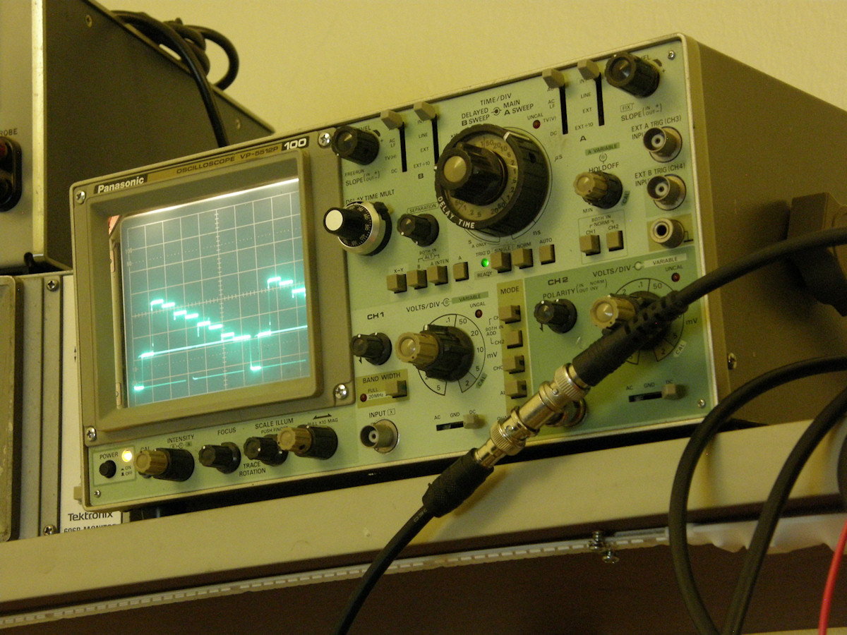
Merry Christmas! My best friend, Joe, loaned me an oscilloscope. - 20141223 Labguy's Christmas miracle. Thank you, Joe. I'm back in business! To celebrate, enjoy the 3JP12, medium persistence orange phosphor CRT. If you remember the age of the 12MHz 386 PC computers, around 1986 or so, then you can remember seeing this phosphor in many monochrome text and graphics terminals. The persistance is about one second. How many phosphors have we seen so far? Let's review. There was P1 green. We've seen P4 BW TV phosphor in the Cyclops project. Next was P7 radar phosphor. Then there is P11 turqoise blue. And finally P12 medium persistace orange. (In the video) there was P31 blue/green phosphor. That's six CRT phosphors so far. Coming soon, P14 and PSP (like P24). Both are scanning phosphors. One is UV monochrome. The other is for color scanning. Gives you chills doesn't it? This project is continued on the [Electrostatic CRT Deflection Amplifier] project page. Comments or Questions? [EMAIL] REFERENCES:
1. Meet my favorite maker, Eric Schlaepfer. Eric's web site is called TUBE TIME, and is an excellent resource on many cool electronic things. Eric is a regular Mr. Science. Be sure to see his exhibits at the San Mateo Maker Fair. [HOME] [ELECTRONICS PROJECTS] Created: December 12, 2014 Last updated: February 22, 2015 |