|
LabGuy's World: Electrostatic CRT Deflection Amplifier
Continued from [Electrostatic Cathode Ray Tube Project 1] 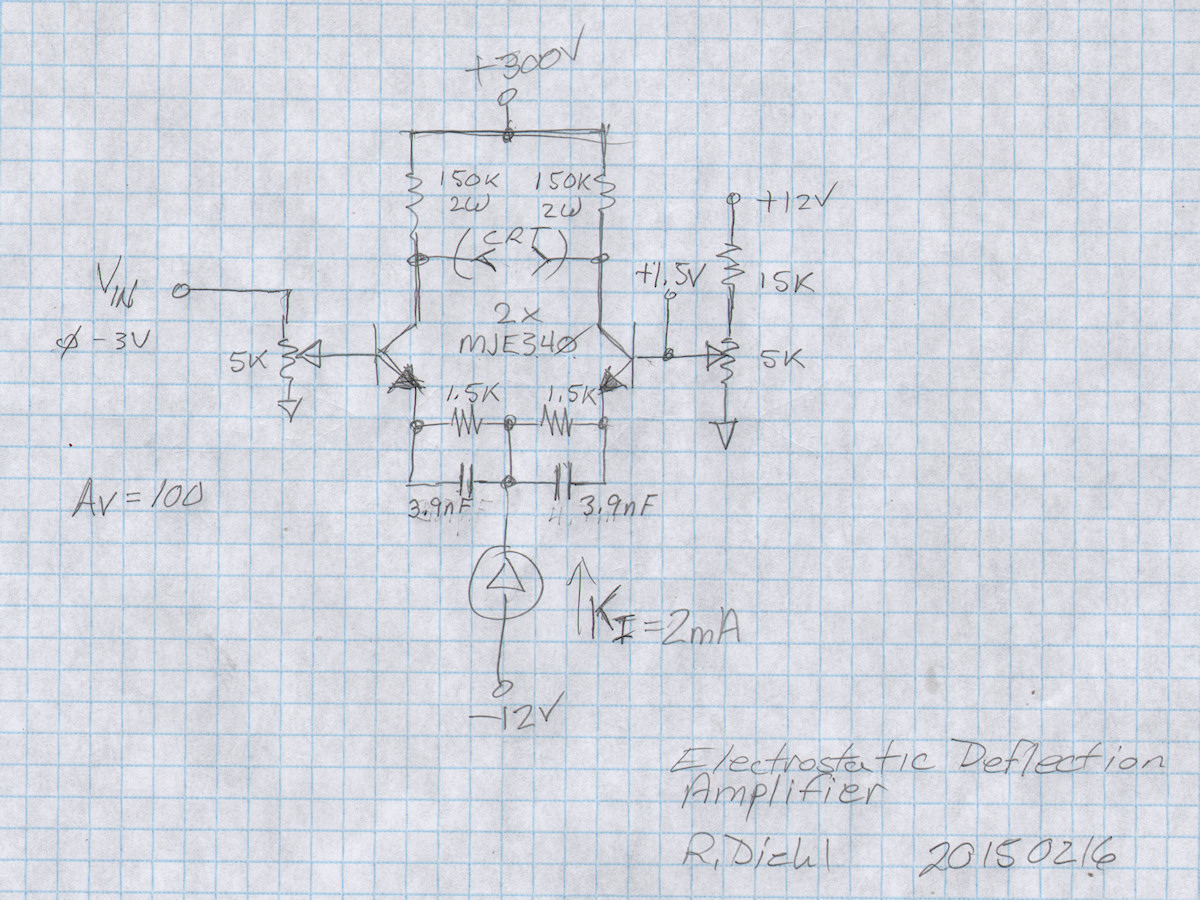

New and improved high voltage differential amplifier - 20150216 Project goal: Develop a simple, easy to reproduce, high bandwidth, high voltage linear differential amplifier for driving the deflection plates in electrostatic cathode ray tubes. I have settled on a gain of 100 for the new amp. The input voltage range is 0V to +3V. The output is 0V to +300V on the positive output and +300 volts to 0 volts on the negative output. Up to this point, the amplifier bandwidth has been disappointing. You can see this clearly in the first photo below. This issue has finally been addressed and corrected. This page actually contains many seaparate, yet interrelated, electronics projects. One is the deflection amplifier part and the latter are two compact power supplies / voltage regulators. A three hundred volt power supply to run the deflection and a negative twelve volt DC-DC inverter to supply the -12 volt bias. PLEASE TAKE NOTE. Do not build the circuits in the early parts of these articles. These are representative of the evolutionary path to the final design. The latest circuits are always at the end of my articles. This deflection board has a new built in 300 volt power supply. It is the red board on the left side of the vector board. Needless to say, it is going through some growing pains... as usual. It is working in principal, but overheats after a fasion. I don't have quite the right capacitor values for the job. But, proved the principals work. Will publish updates about that and full schematics when all those problems are solved. 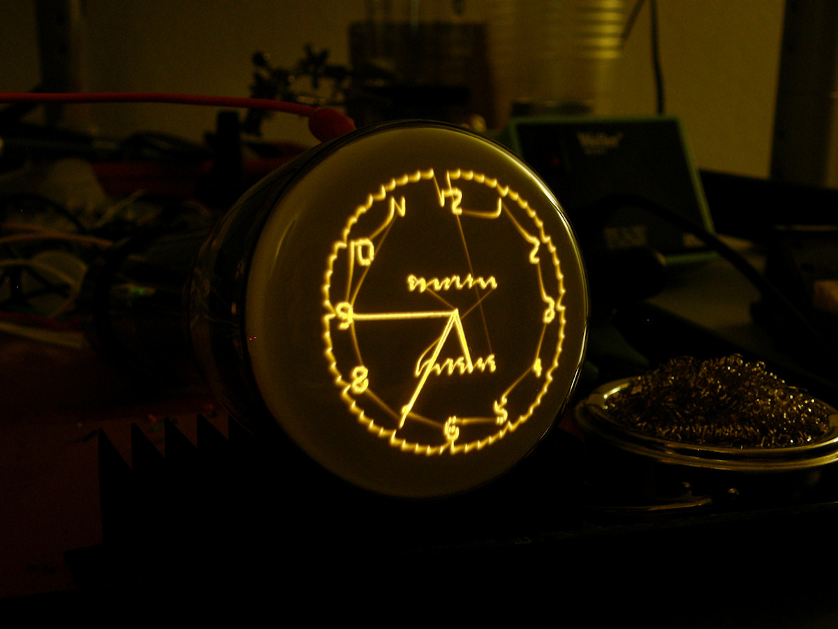
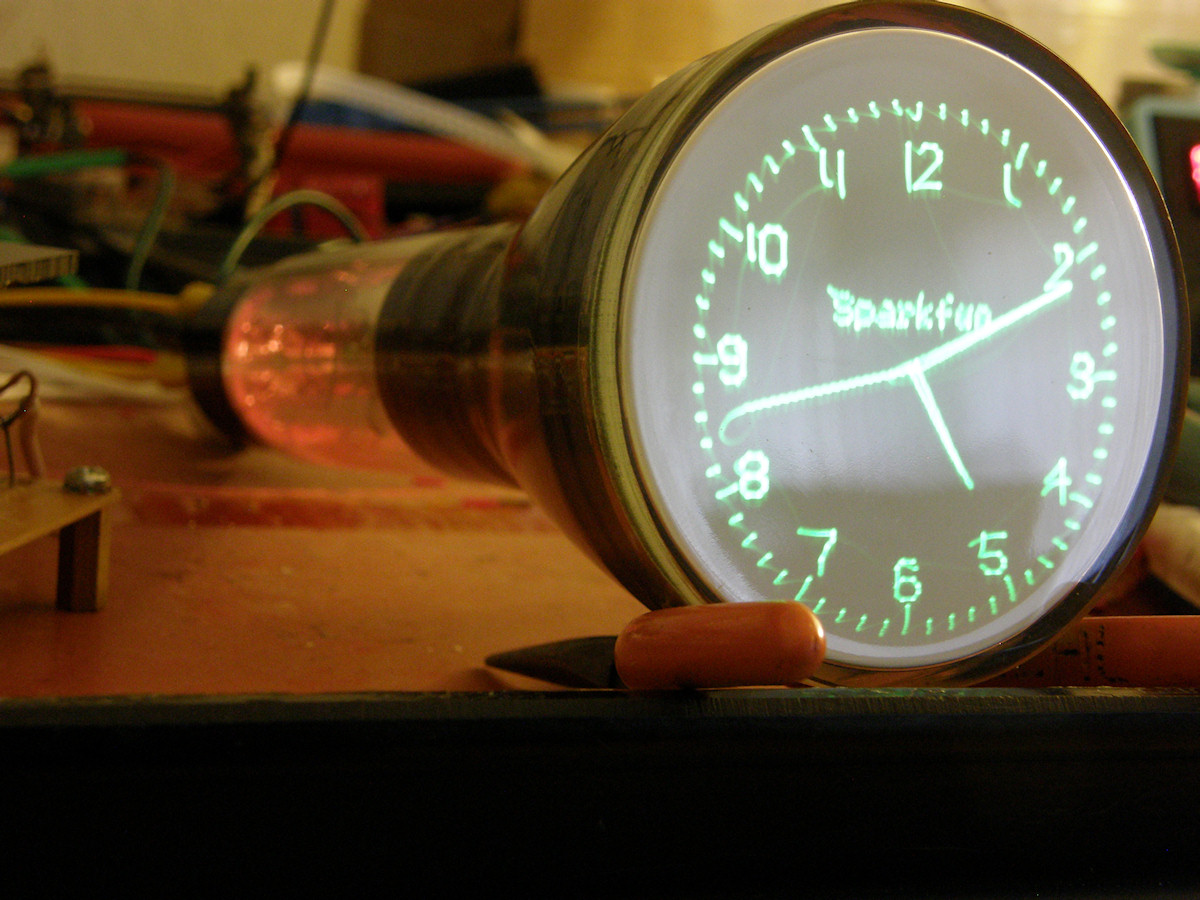
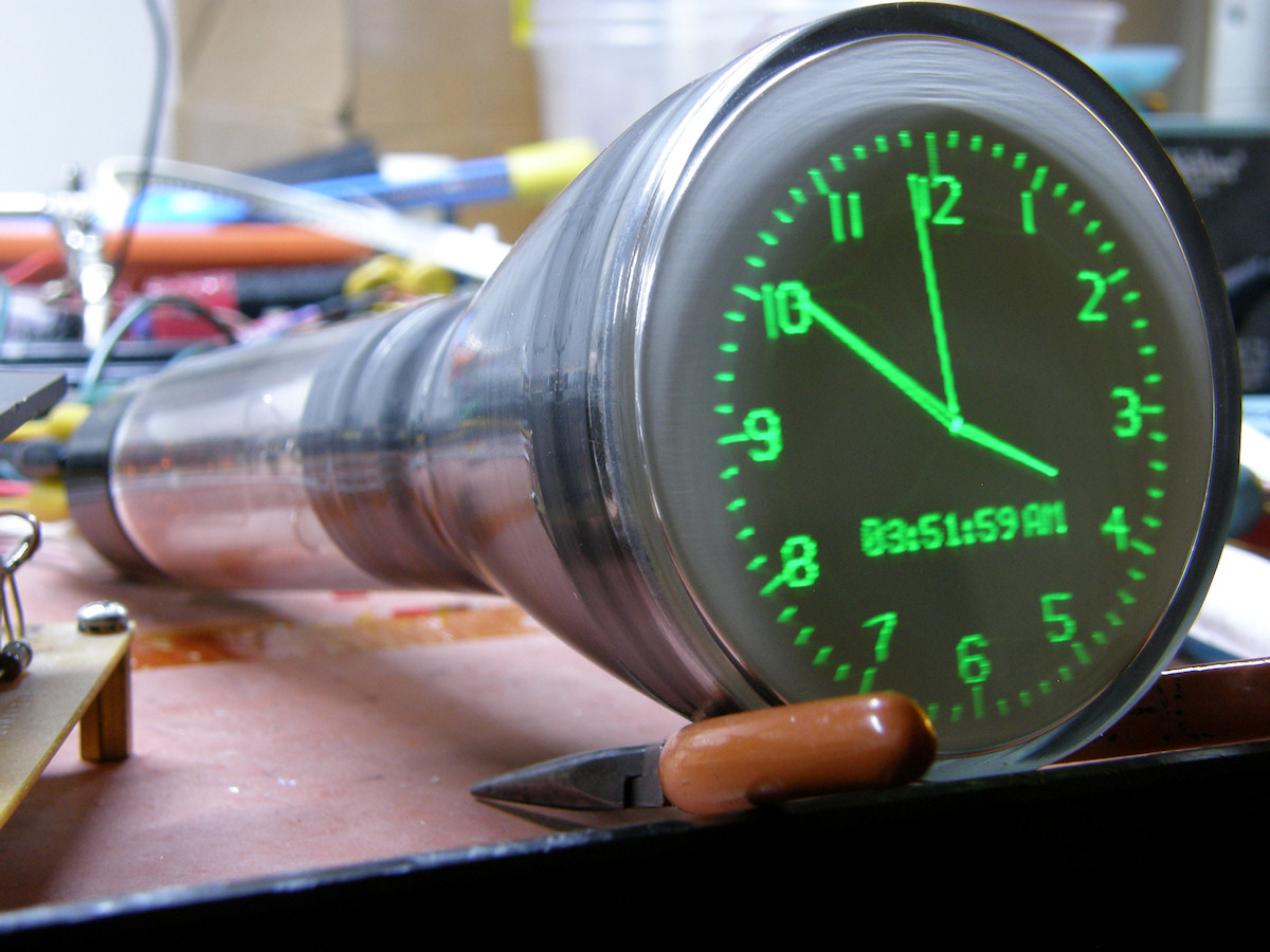
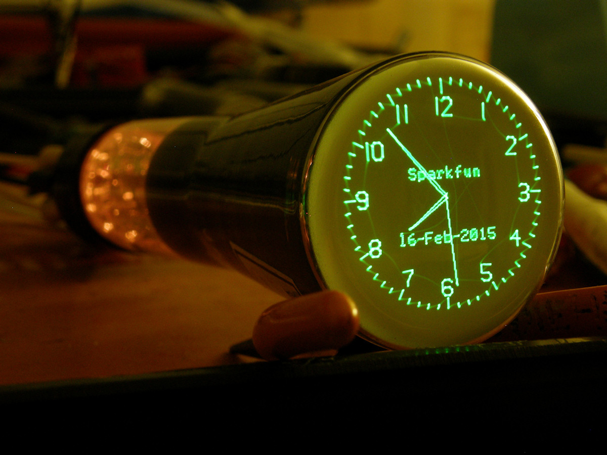
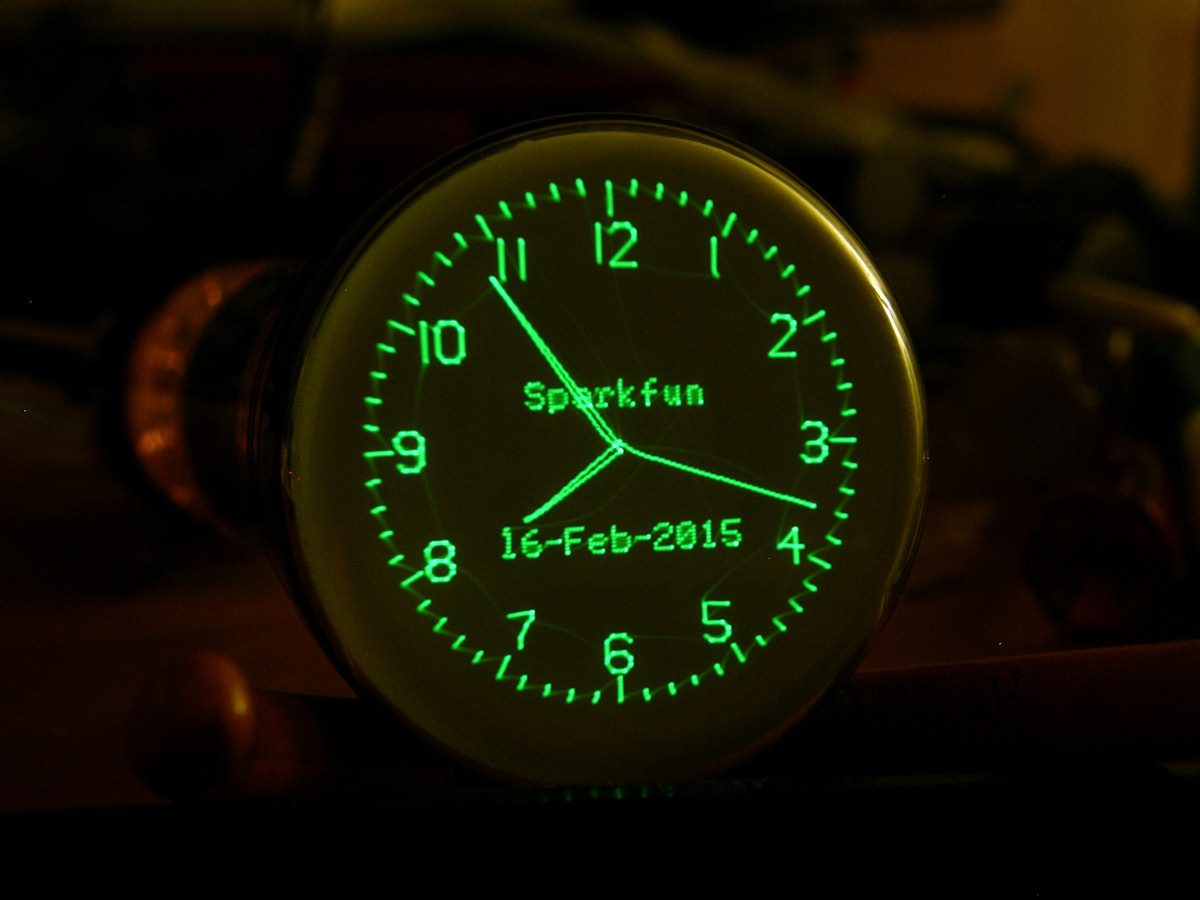
Uncompensated amplifiers, 4.7nF compensation and 3.9nF compensation - 20150216 Over the past three days, I have tried various designs to make this amplifier work better... and faster. I even added a very expensive op amp which only made a great oscillator. So, I resorted to my original simple two transistor design. The greatest improvements were in getting the run away gain under control. This was accomplished by installing the 1.5K emitter resistor in the differentaial amplifier. The ratio of the emitter resistors to the colector resistors is roughly the DC gain of the circuit. 150K to 1.5K is 100. This solved the gain issues and made the pots less sensitive to set. However, the frequency response problem remained. This can be tweaked by applying an appropriate amount of AC bypass to the emitter resistors via parallel capacitors. Because there are four legs in the circuit and each requires a capacitor, performing the test was labor intensive. Starting with 10pF, and increasing by ten times each step, I installed and removed four 10pF, four 100pF, four 1nF and finally four 10nF capacitors. The 1nF gave no visible effect. With the 10nF, the amplifier was overcompensated and made the screen characters look like Klingon. Yes, I should have taken a photo. So, having reached this point, we resorted to successive approximation. If 1nF did nothing and 10nF is too much, we then split the difference and try five nano Farads. The nearest standard capacitor value is 4.7nF. Four 4.7nF caps were installed and the image in the second photo above shows the result. Much better. But, there was still some overshoot visible, so I stepped the caps down by one more value to the 3.9nF (3900pF / .0039uF) as shown on my hand drawn schematic above. The results are excellent now. We can clearly read the characters in the digital text portion of the display. And that is without applying the blanking pulses to the CRT. The beam jumps from vector to vector so fast it is invisible. This was how early television accomplished grey scale. Its called velocity modulation. It works terrible for TV. Looks great on the Sparkfun Scope Clock and my new 3RP1A CRT. 
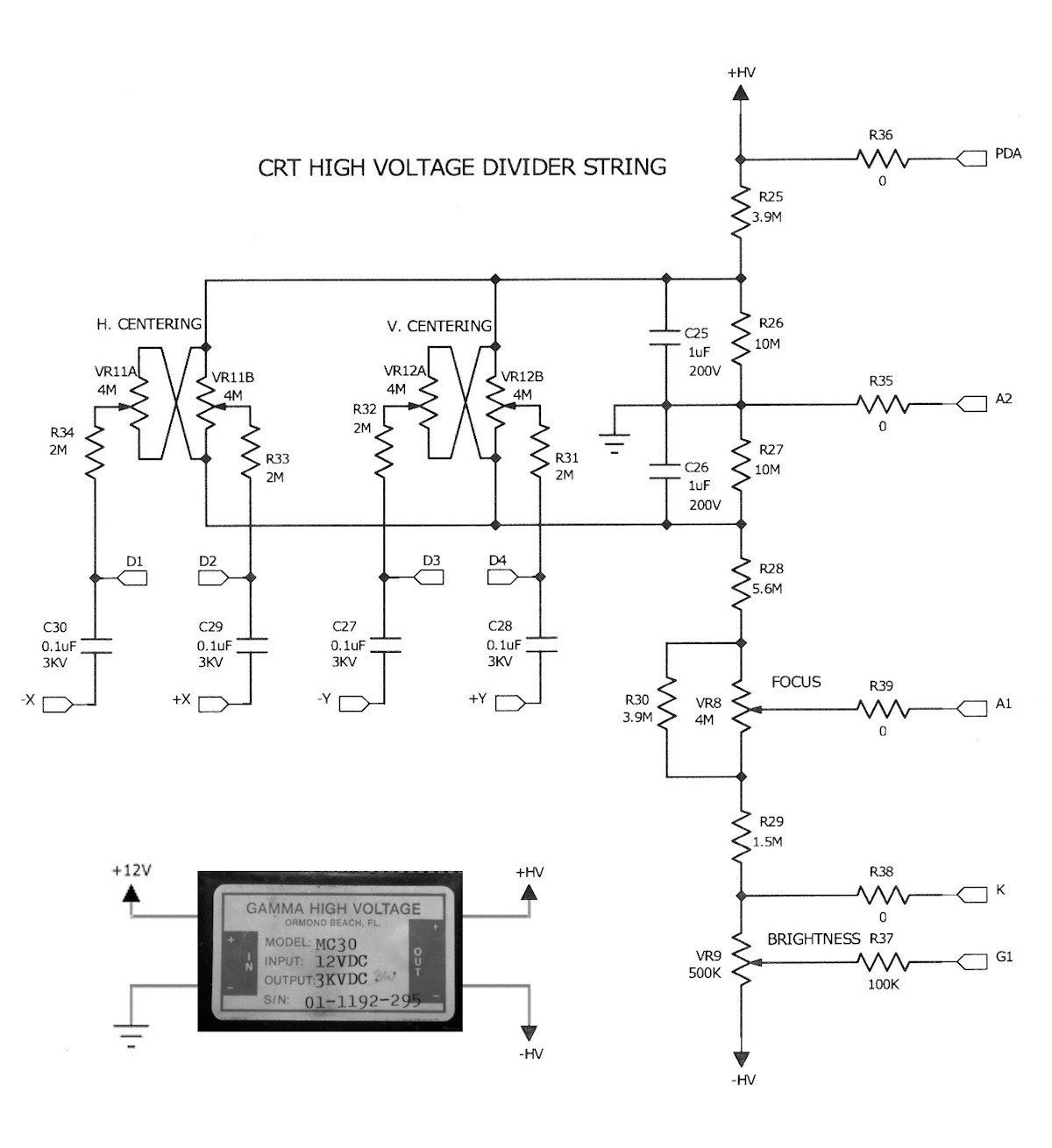
The test set up of my scope clock, deflection amps, and CRT bias board - 20150216 In the foreground is my CRT bias board. The schematic is shown again for your convenience. The CRT in this test is marked WX 5078P1. I truly believe it is a clone of the 3RP1A, three inch flat face CRT. Pin out is identical. On the left is the Scope clock board in red. My new deflection amplifier is in the background. The four ceramic capacitors sticking up in the air are the deflection AC coupling capacitors. These signals are summed to the deflection plate DC levels provided by the CRT bias board. Works like a champ! Its down to three input power supply voltages now. Tube heater 6.3VAC from the little iron core transformer sitting just behind the black tray. Then there is plus and minus 12 volts provided by my general purpose bench supply. Plus 12 volts is drawing about 400mA and negative 12 volts is drawing less than 20mA. The +12 volts is powering two DC inverters. One to make +300 volts and one to make 3KV for the CRT electron gun. 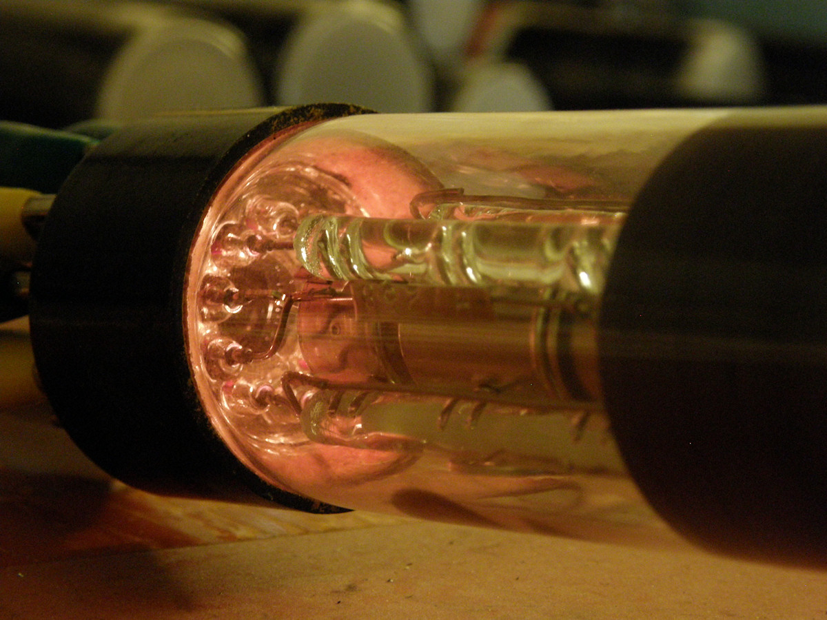
Checking out my 2BP1 two inch CRT - 20150216 I got a heck of a deal on three 2BP1 two inch electrostatic CRTs. With their matching sockets and several pieces of mu metal foil. Enough to wrap two of the tubes. Bonus! This has to be the sharpest, crispiest CRT I have seen so far. Extremely well focused. You can almost read at night by the light of the tube's heater! All three CRTs are good and bright. Sweet. I have been tossing around the terms, "frequency response" and "bandwidth" rather loosely. I need to clarify that the capacitors I added to the diff amps do set the frequency and phase response as well. The capacitance of the CRT connected to the outputs and associated wiring will also effect these parameters. So, trimming the capacitor values on your copy of this design will probably be necessary. But, this is a great starting point. And last, since I don't have a sweep generator, I can't state the exact frequency response of the amplifier. The improvements I claimed were based on simply observing the scope clock output on the CRT. I try to teach on the assumption that my readers have very few resources at their disposal. 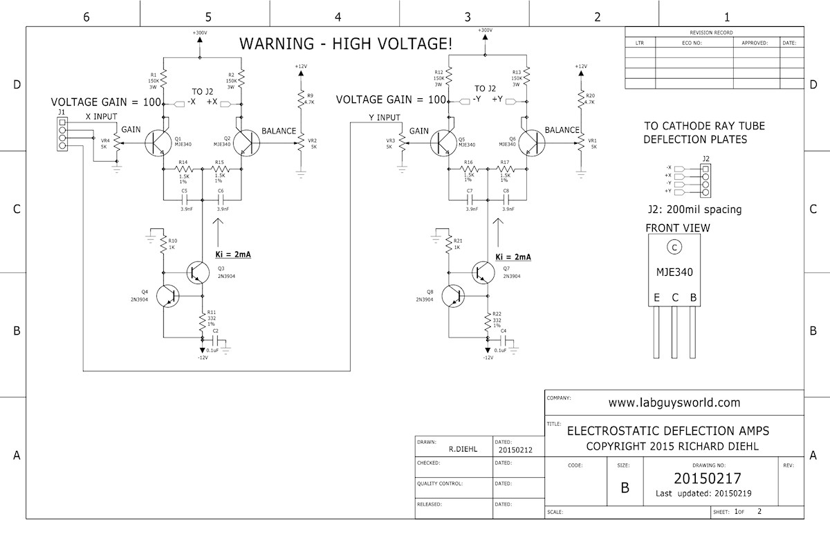
Deflection Amp and CRT Bias Schematics - 20150217 Here is a copy of the [schematic ] in PDF. In review I can see that we achieved the goal of simplicity. This is a very inexpensive solution, and far simpler than all the other scan solutions I have seen and tried. I do not claim that the performance is any better than the more complex designs. Just simpler and cheaper. The MJE340's are less than a dollar a piece at Digi-Key. It's low power (as vacuum tube circuits go). Both amps combined pull a total of 4mA constant current at 300 volts. 1.2 Watts. For those of you who want to make your own CRT driver to go with your [SparkFun O-Clock - AVR Oscilloscope Clock] boards, this is a very economical and simple solution. Please note that this is an AC coupled amplifier. The outputs of the amplifiers are coupled to the CRT bias board via four .1uF, 1KV ceramic capacitors. C27, C28, C29 & C30. The inputs to the amplifiers will respond to DC drive. However the DC is blocked by the series capacitors. So, the input voltage must be constantly changing, like scope clock vectors or TV raster. Anything over a few dozen Hertz will work, up to the frequency limit of the amps, which has yet to be measured. The advantage of AC coupling the deflection is that the deflection amplifier does not have to operate at the same voltage as the CRT's second anode. These tubes require the average DC of the deflection voltages to match the voltage of the second anode. If a voltage difference is created, it will distort the electron beam spot, reducing resolution as the spot moves away from the center of the screen. My bias board takes this into account. I drew the schematic to show this as clearly as I could. Observe that the wipers of the centering controls are aligned with the A2 connection on the voltage divider. These are all at system ground voltage. The output of the 3KV power supply is fully isolated and floats relative to the system ground. 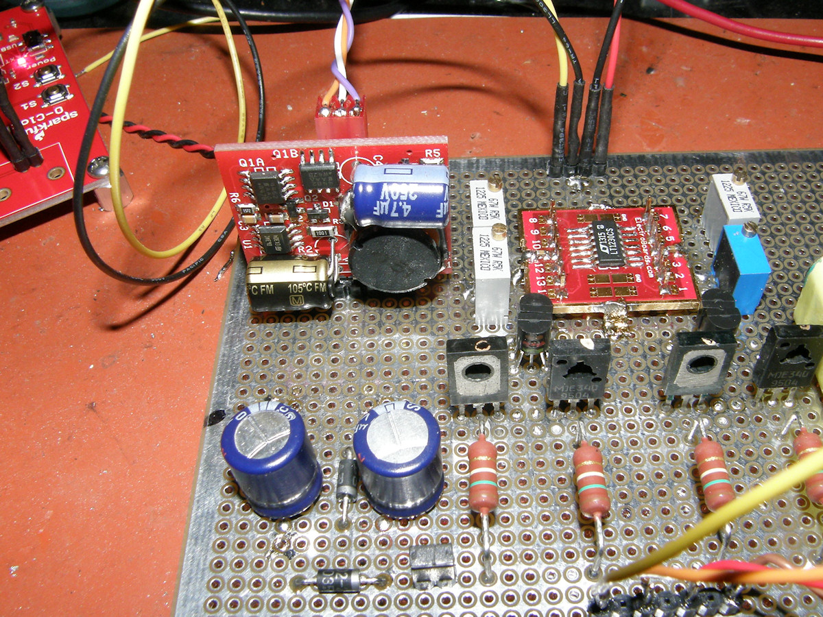
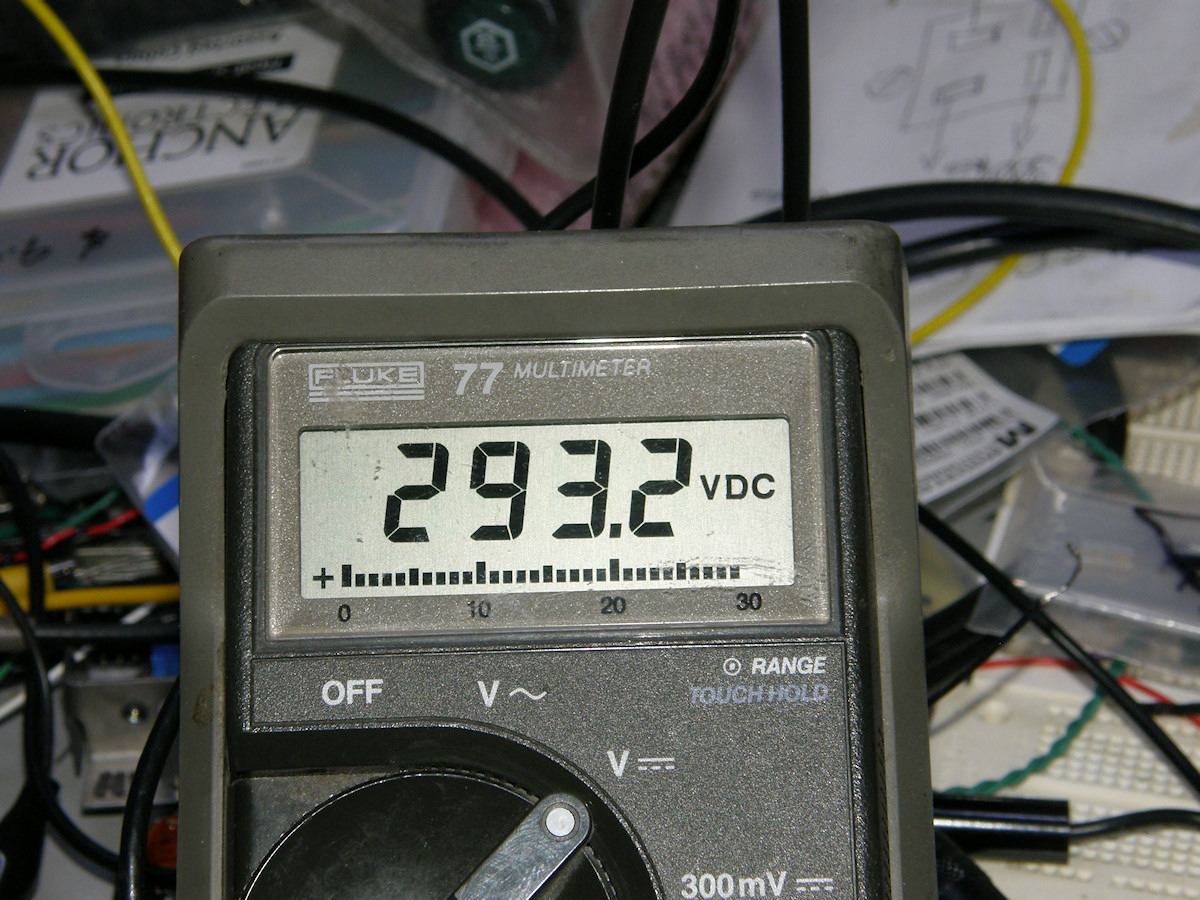
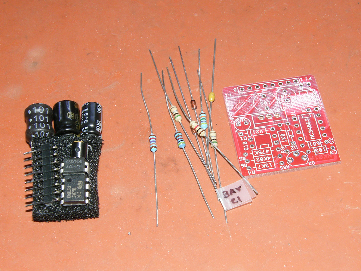
High voltage power supply is up and running - 20150220 The [Threeneurons HV power supply], model NK01, arrived today. Fifteen bucks is a great price for this gem. By itself, it produces up to 190 volts. (positive polarity only) Up to 5 watts of total power. With the addition of a couple of capacitors and fast switching rectifiers, it can produce up to 380 volts. It is easy to use too. You hook up +12 volts, set the output voltage with one additional resistor and turn it on. See the resistor value vs. output voltage table at Threeneuron's site. As of February 22, 2015, this power supply is available in kit form on Ebay, seller: "Tortugascuba", auction number: "151587665616". The full Ebay auction title is, "High Voltage Power Supply Kit - 45V to 190V Out - for Nixie, Old Radio - Kit". Less than ten bucks each. What a bargain! Five still available. Get 'em while they're hot! The first photo shows the little red power supply standing upright on the left side of the scan amp board. Just in front are the two diodes and two 1uF, 450V capacitors I used for my voltage doubler. Caps rated as low as 200V will work just as well. I suppliment the 300 volt output with a 1uF, 400V mylar film capacitor, not shown. But, visible in the second photo on this page. The 1.5K voltage set resistor gave a boost output of 293 volts. That's close enough to 300 volts for the moment. 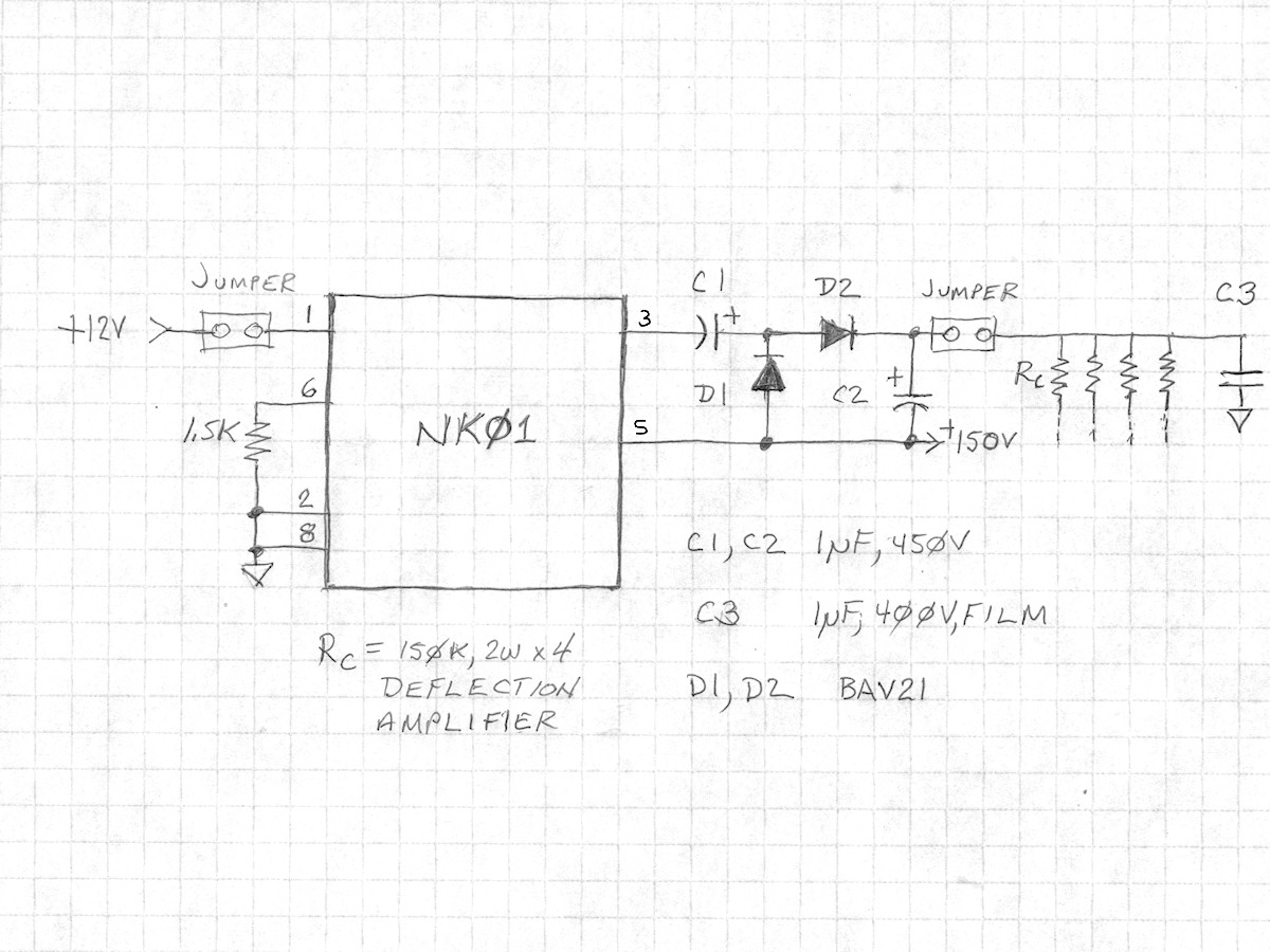
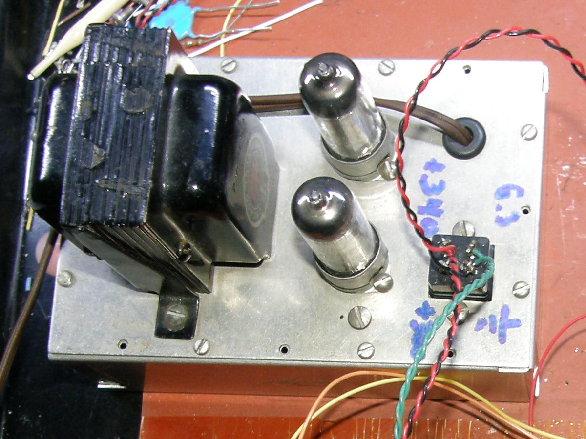
NK01 high voltage power supply schematic and the cute little monster it replaces - 20150221 It can not get much simpler than this. It is also a much smaller and convenient solution than my old 1960 home brew power supply. Adding a couple of capacitors and diodes to the NK01 creates what is known as a boost supply. The 150V pulse (pin 3) is AC coupled by C1 whose output, in turn, is lfted up to the 150V DC (pin 3) level by D1. The pulse is added to the +150VDC and then rectified by D2 and stored on C2, which is also lifted, or boosted by 150 volts, totalling 300 volts. The neat thing is that the capacitors don't have to withstand the full output voltage. C1 and C2 can be rated as low as 200 volts. C3, of course, does have to be rated for 300 volts or more, as it sits right across the 300 volt output. I chose a mylar film capacitor because of its superior high frequency filtering performance over an electrolytic type. Note that I installed jumper plugs to allow the power supply to be isolated for testing and setting. The MJE340 transistors can not tolerate much more than their specified 300 volt rating. It would do no good to turn on the supply and hit the transistors with more than 300 volts by accident. So, the output jumper is first opened and the operating voltage verified. The next step will be to change the 1.5K resistor to a 1K resistor in series with a 1K rheostat. This will allow precise setting of the output voltage before applying it to the amplifier. These jumpers also allow connecting an ammeter for measuring the input or output current. 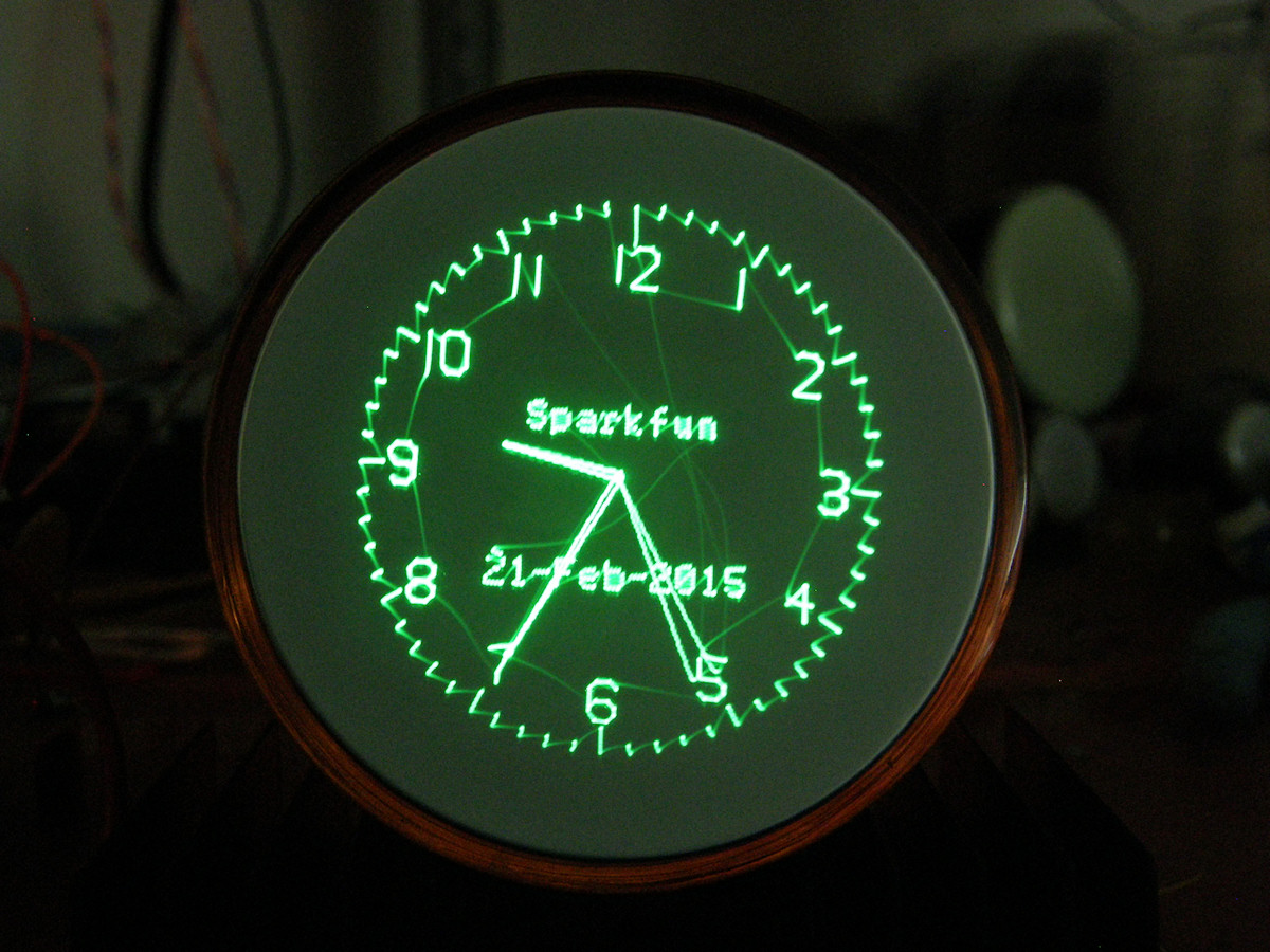
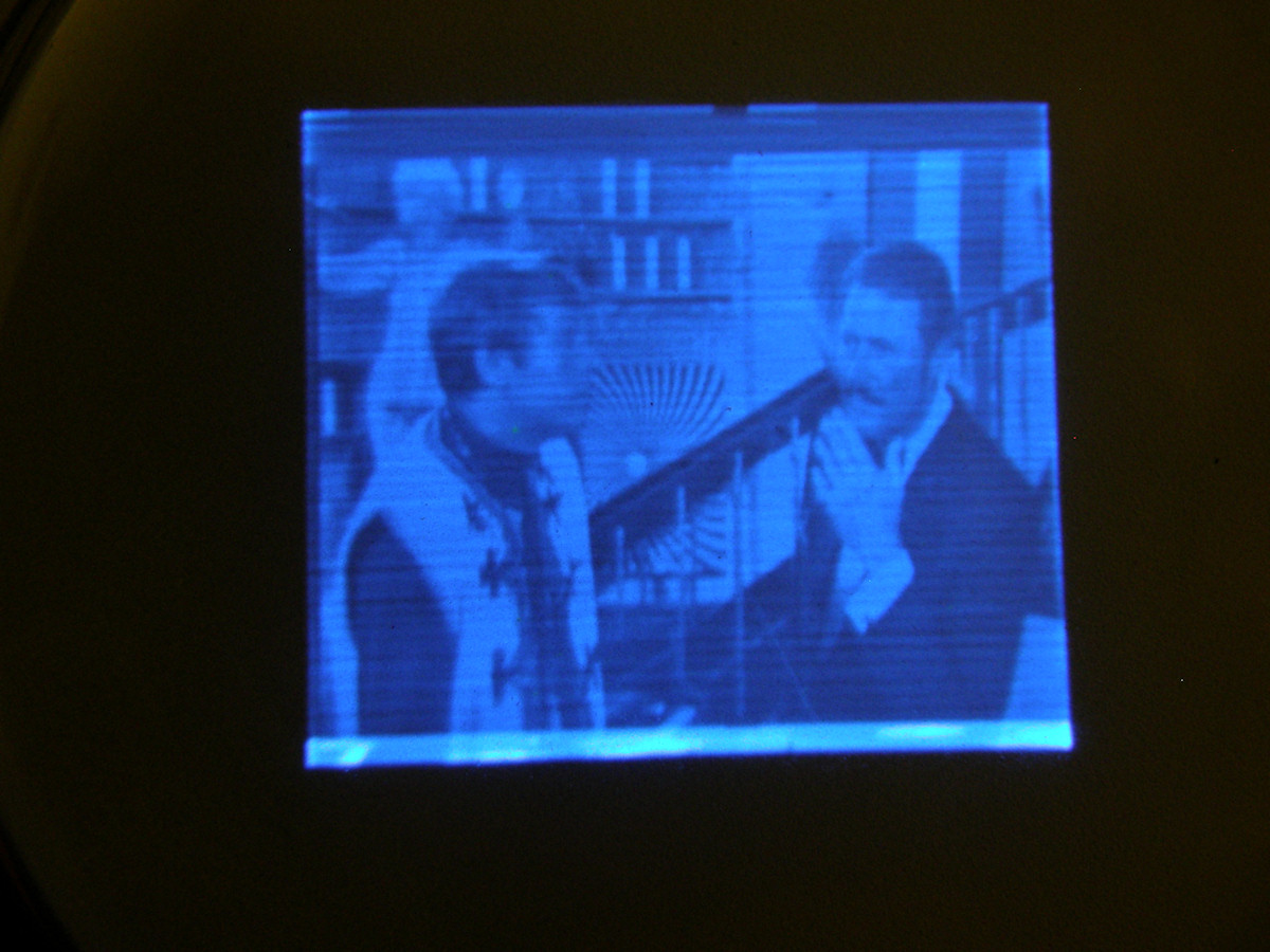
WX 5078P1 (3RP1A?) cathode ray tube running with new power supply - 20150221 The +150 volt output will not go to waste either. It is going to power the blanking and video amplifier which is coming soon. You can see in this photo of the 3 inch WX 5078P1 CRT, the frequency and phase reponse is a little different than the previous photo of the 2BP1. Also note that the visible retrace streaking that will be eliminated by the blanking amplifier. 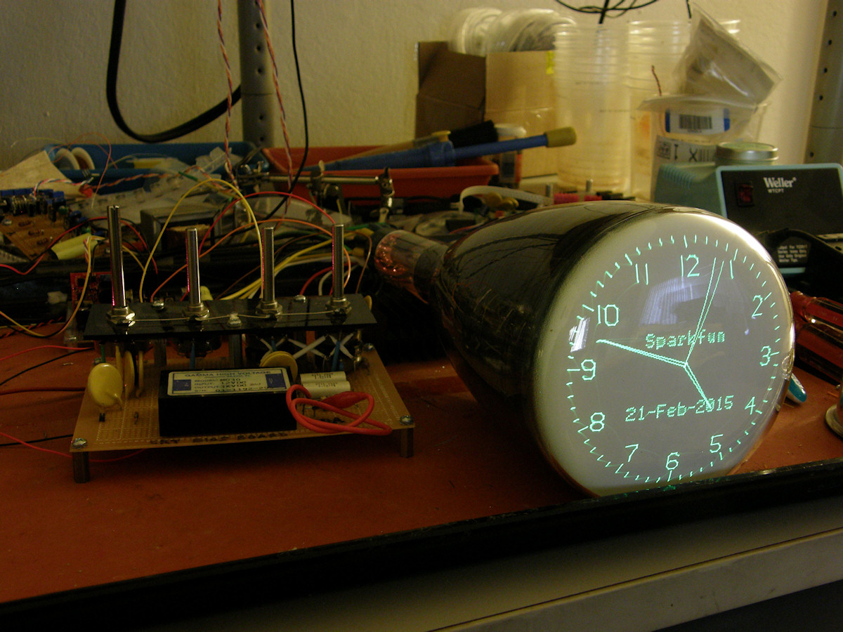

5UP1 and 5DEP1 five inch cathode ray tubes work awesome too! - 20150221 I got a very good deal on two five inch electrostatic CRTs today at [Halted Specialties Company], my favorite surplus store, in Sunnyvale. Too good to pass up. Both tubes worked perfectly in my test system. These are the first five inch tubes I have tried with it and I am delighted with the results. The size control on the AVR Scope Clock board can overdrive the scan beyond the edges of the screen. The first photo is of the Sylvania 5UP1. It has a domed face envelope that was low cost to manufacture and withstands air pressure well. It is a thin tube that would be very easy to pop if mishandled. These were used in a large number of cheapo oscilloscope kits in the late 1960s and all through the 1970s. . I think the 5UP1 makes a better image than the next tube. What do you think? The second photo is of the Hitachi 5DEP1 flat face CRT. These were the upgrade tubes for the cheapo oscilloscopes, mentioned previously. Same connections, same voltages. Plug-n-Play! Thicker bottle on this one. Probably intended for portable operation while the 5UP1 is for a scope that sits on a bench most of the time. Flat face tubes are generally designed for photographic applications as well. Back in the day, a bulky Polaroid camera could be mounted to the scope bezel to get screen shots. Ah. Those were the days... 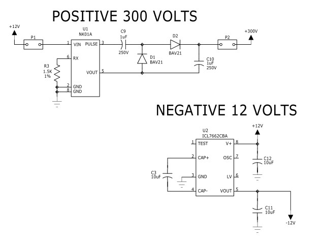
New power supply schematics - 20150225 Here are the cleaned up schematics for the 300 volt converter and a yet to be built and tested negative 12 volt inverter. The latter is for the purpose of making the deflection amplifier run on a single +12 volt power supply. It is currently being powered by a pair of adjustable power supplies. The only load on the -12 volts is the pair of current sources that feed the differential amplifier. The load on the converter is a tiny 4mA. Both of these power supplies are extremely simple. See the earlier entries about the NK01A power supply. The [ICL7662CBA+ is available from Digi-Key] and other sources. The datasheet is at the link. Here is a PDF of the complete [scan amplifier] schematics, as of 20150225. 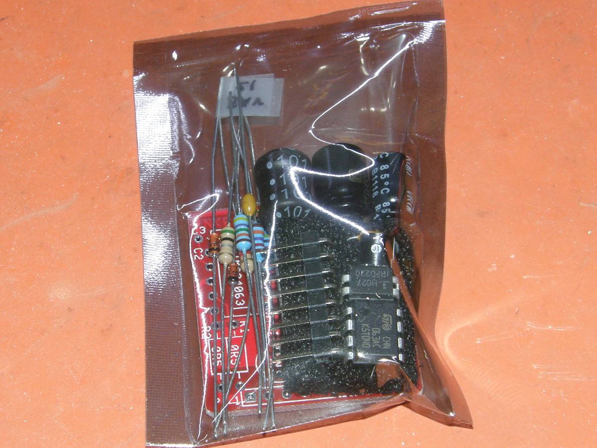
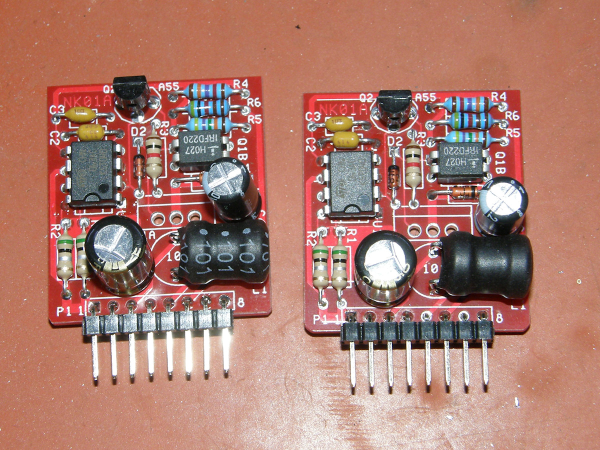
Threeneuron's High voltage power supply kit - 20150303 Received the first two kits yesterday. Last evening, I assembled the first unit in under twenty minutes. This evening, I completed the second module in less than 15 minutes. Assembly was pretty self explanatory. But, in case of doubt, a visit to the [Threeneurons HV power supply] instruction page made the job a cake walk. Both units were fully operational upon completion. As expected. The best part? This kit sells for less than ten dollars! A perfect power supply for small vacuum tube projects that need a few hundred volts at low current. Total power capability is over 5 watts. "Tortugascuba" sells these on Ebay. One in kit form and a second one that is preassembled. The latter for a slightly higher fee, of course. 20150304 - The samples of ICL7662CBA+ DC voltage inverters arrived. I installed one immediately and, what do you know, it works! At this point, the electrostatic scan amplifier operates from a single +12 volt supply, cutting down the wiring clutter quite a bit. 
Scan amplifier running with the Tiny TV board - 20150306 Just on a lark, I decided to connect the scan amp to the Tiny TV board. The severe scan fold over distortion I observed earlier is now gone. That was due to the incorrect gain and frequency compensation I had designed into the scan amps. Once I thought the problem through and fixed the gain, the amps have behaved more or less as predicted. The ultimate goal of simpler final circuits makes getting there that much harder. Anyone can throw dozens of additional components at a problem. I am trying to design my circuits with the goal of minimalism. Using the fewest components necessary to make it easier for my followers to reproduce the circuit. In its day, this method was employed because for each vacuum tube stage that could be eliminated, three to five watts of power could be saved. And that does not include the cost of the components saved as well. The bright band across the bottom of the image is the vertical ramp reaching 5 volts before the scan period has ended. The bar is more than a scan line tall because of the AC coupling. As soon as the ramp stopped changing, the voltage on the plates starts to return to zero. That's the center of the image. At any rate, that has since been repaired by increasing the scan ramp capacitor to a larger value. The dark band across the top of the picture is the vertical blanking period which is not 100% blanked by the very low voltage signal. I still have not yet constructed a high voltage video amplifier. Still in search of a very simple design. This would take the one to three volt video input and step it up to between 30 and 60 volts with at least 3MHz bandwidth. Preferably more. I had previously modified the CRT bias board to accept a video or blanking signal input. This is accomplished by AC coupling the input video signal to the control grid (G1) of the CRT. This is the Z term in "XYZ CRT display". I connected the approximately five volts of video, produced by the Tiny TV board, directly to the CRT bias board Z input. Turning the brightness control way down and photographing in low light, there is quite a nice picture being reproduced on my 2BP11 two inch CRT. There is a great deal of detail visible because it has yet to be lost in the high voltage video amplifier. I am impressed with how much image can be produced with only a few of volts of drive on the grid! The horizontal smearing is some form of noise modulating the vertical (and probably horizontal) deflection. I suspect it is switching noise from the power supply. Will work on filtering that out. Stay tuned. This is an active project. Check back occasionally to follow the progress. REFERENCES: 1. [Threeneuron's Pile O' Poo] NK01A High voltage power supply. 2. [2BP1] Datasheet. Two inch electrostatic CRT. 3. [3RP1] Datasheet. Three inch flat face electrostatic CRT. 3. [5UP1] Datasheet. Five inch electrostatic CRT. 4. [5DEP1] Datasheet. five inch flat face electrostatic CRT. 5. [MJE340] Datasheet. High voltagen NPN power transistor. [HOME] [ELECTRONICS PROJECTS] Created: February 16, 2015 Last updated: March 9, 2015 |