|
LabGuy's World: 'Goldmark 1' - Field Sequential Color TV Project
PART SEVEN: Return to converting the video monitor to the CBS 405/72i scan rates. 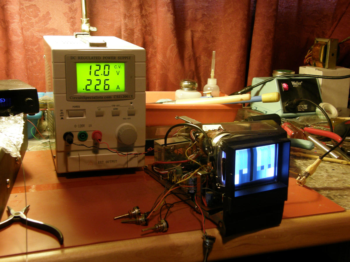
Our target monitor is repaired and ready to resume conversion 20130728 Returning to work on the small Akai video monitor, I made a delightful discovery. The problem that stopped me earlier was not a failed output transistor as suspected. There was a broken trace on a circuit board. The break was in the main power line coming into the monitor. It took but seconds to repair the cracked trace with a jumper wire. Now we can resume the scan rate conversion process. PLAN B 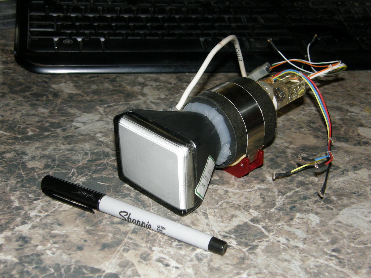
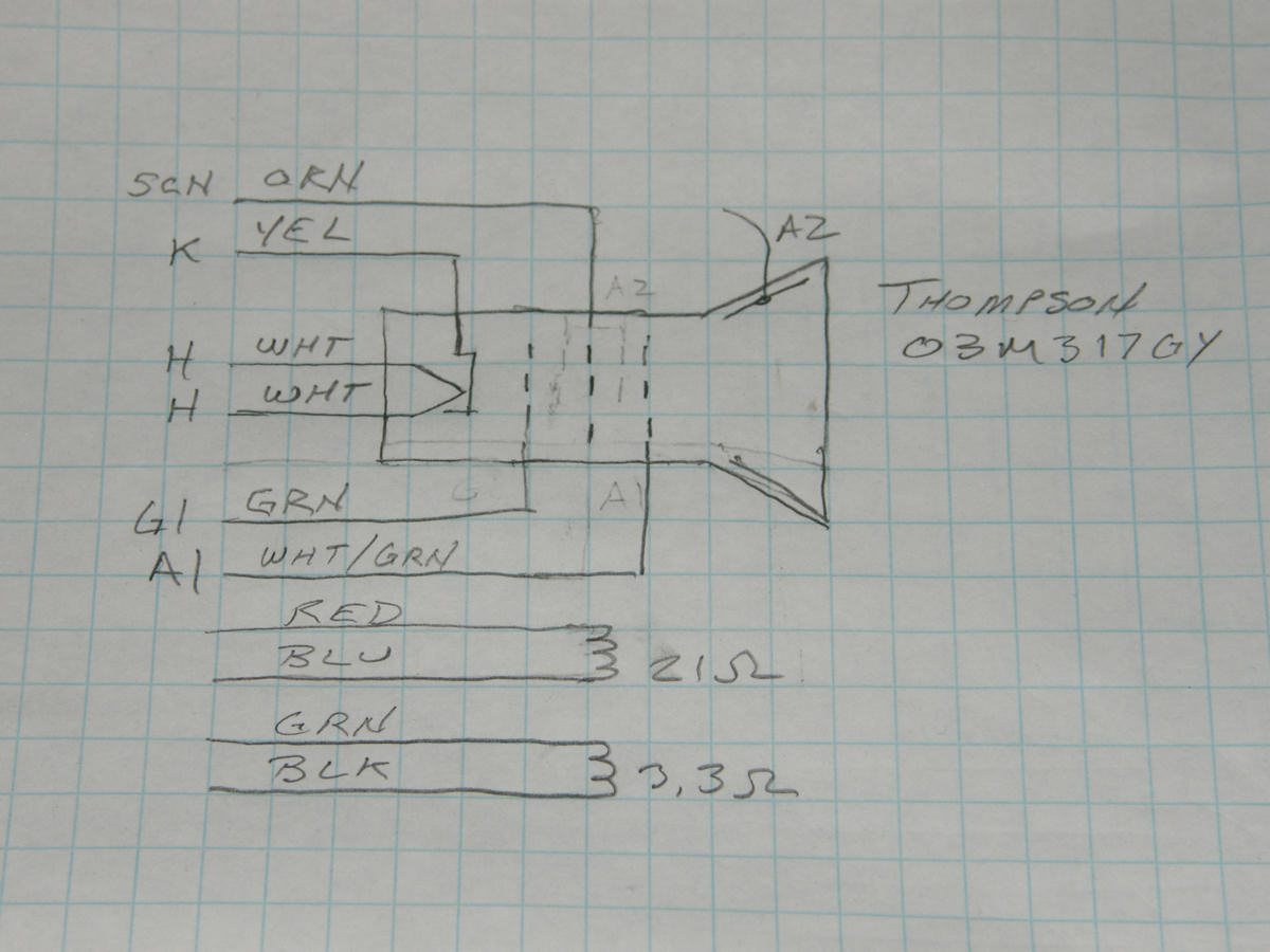
This tube is plan B. Let's hope we don't have to resort to that! 20130728 Plan B. Build a monitor around this tube. A 03M317GY made by Thompson Electronics. (Got the data sheet? Contact me.) It is used, removed from some sort of test instrument. Though I have checked the heater for continuity, it is good, and there are minor burns in the phosphor, there may be an insurmountable problem with this tube. It might have green or amber phosphor. Until it is powered up, how would we know? If this tube does not have P4, blue-white, phosphor, it is too risky to use at this time. At least for the purposes of this project. BACKGROUND AND HISTORY 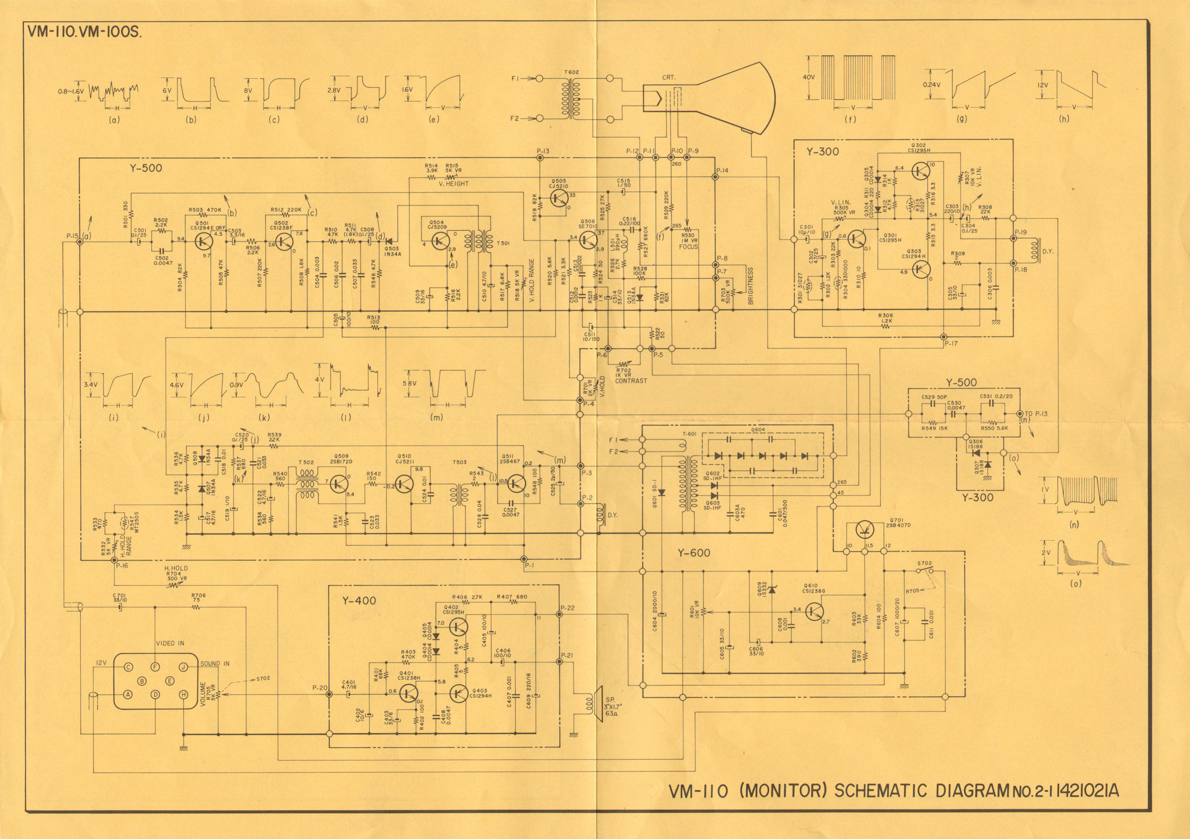
Akai VM-100, 3 inch CRT BW video monitor circa 1972 20130803 This is a 525/60i standard definition video monitor. Intended for portable battery powered operation. This was originally the companion to a portable video tape recorder, the Akai VT-100, 110, 120 or 150. Since I have three or four extra of these monitors, and adequate documentation, they fit into my budget perfectly. BASELINE TESTS 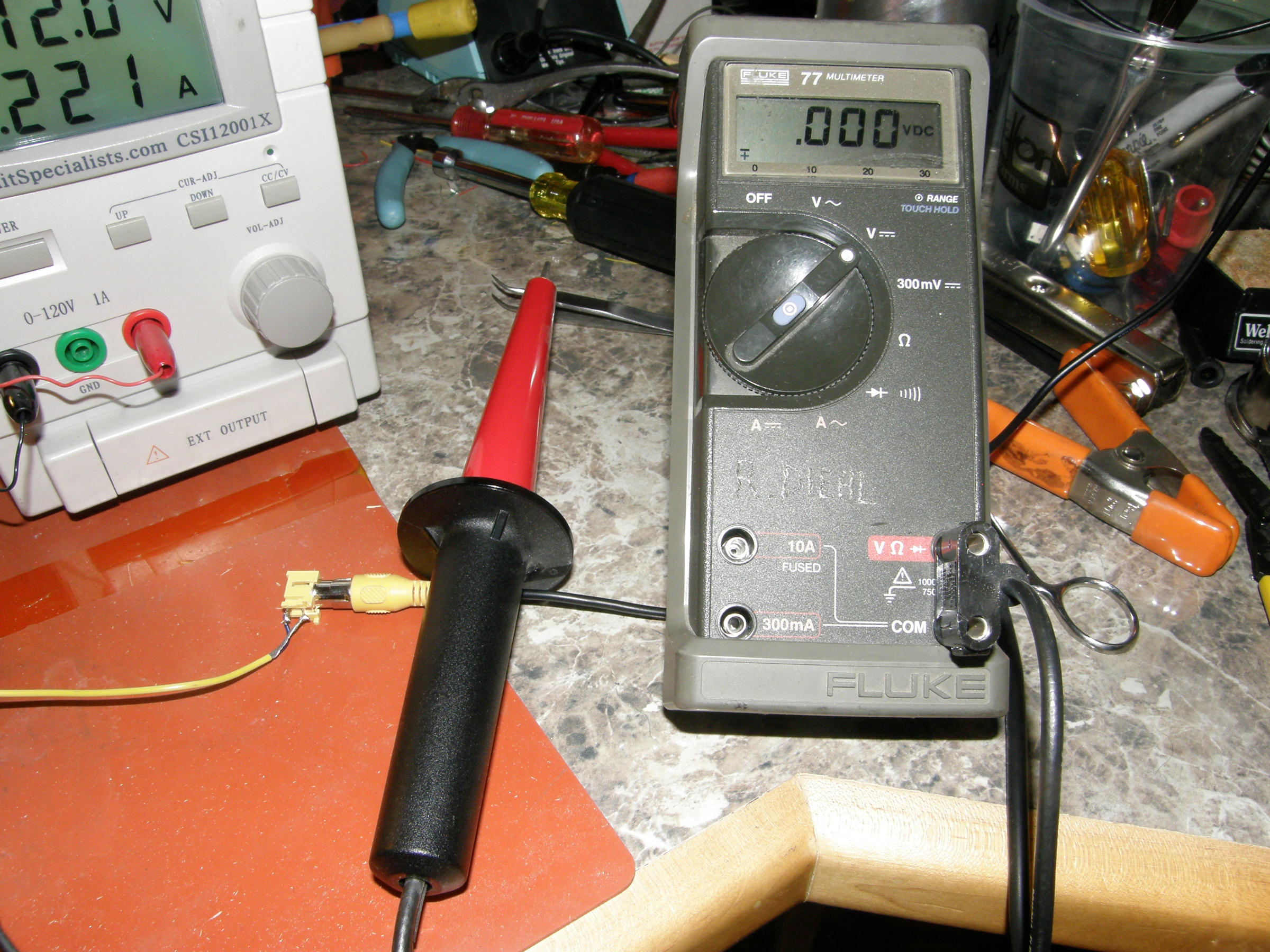
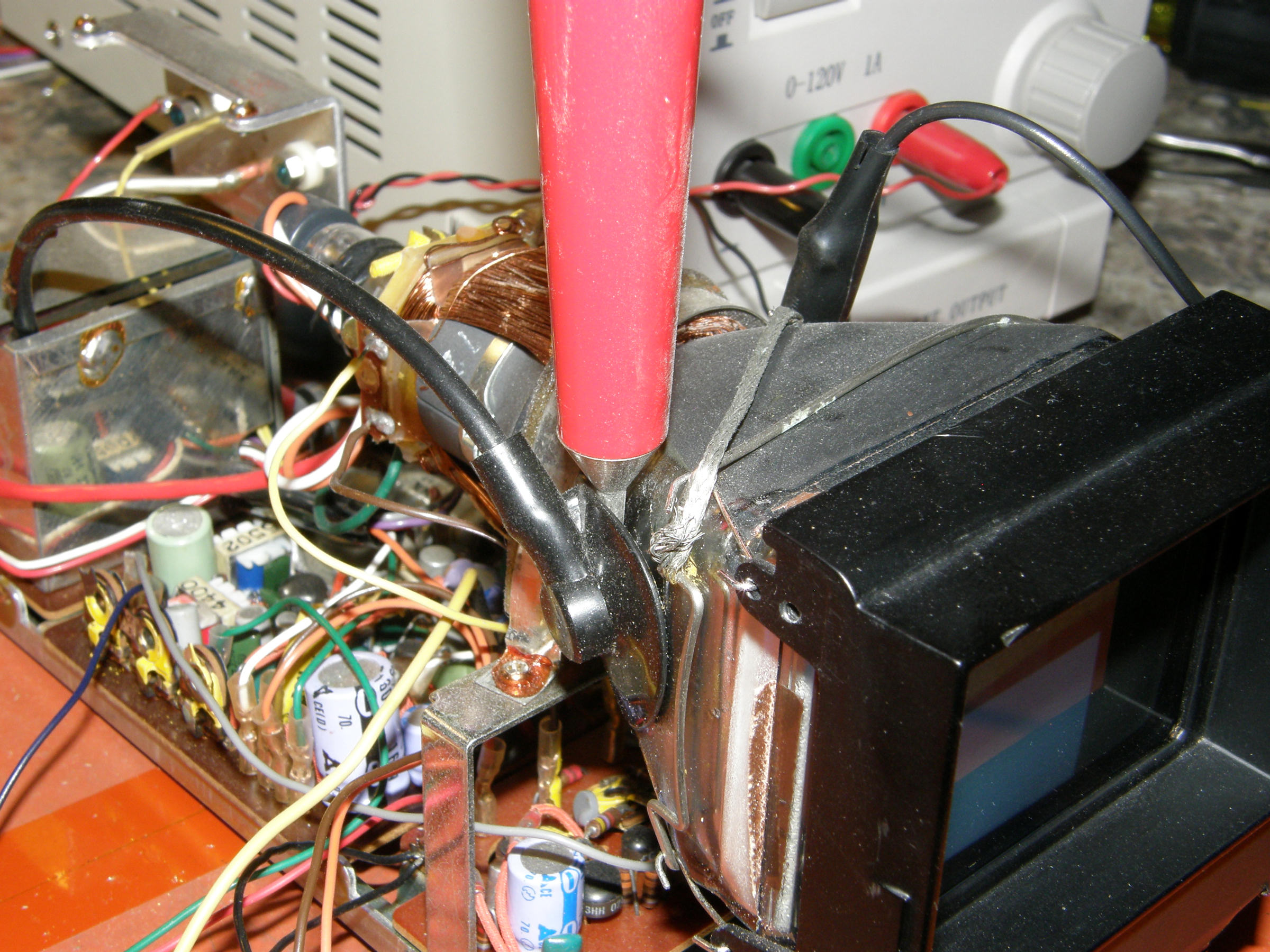
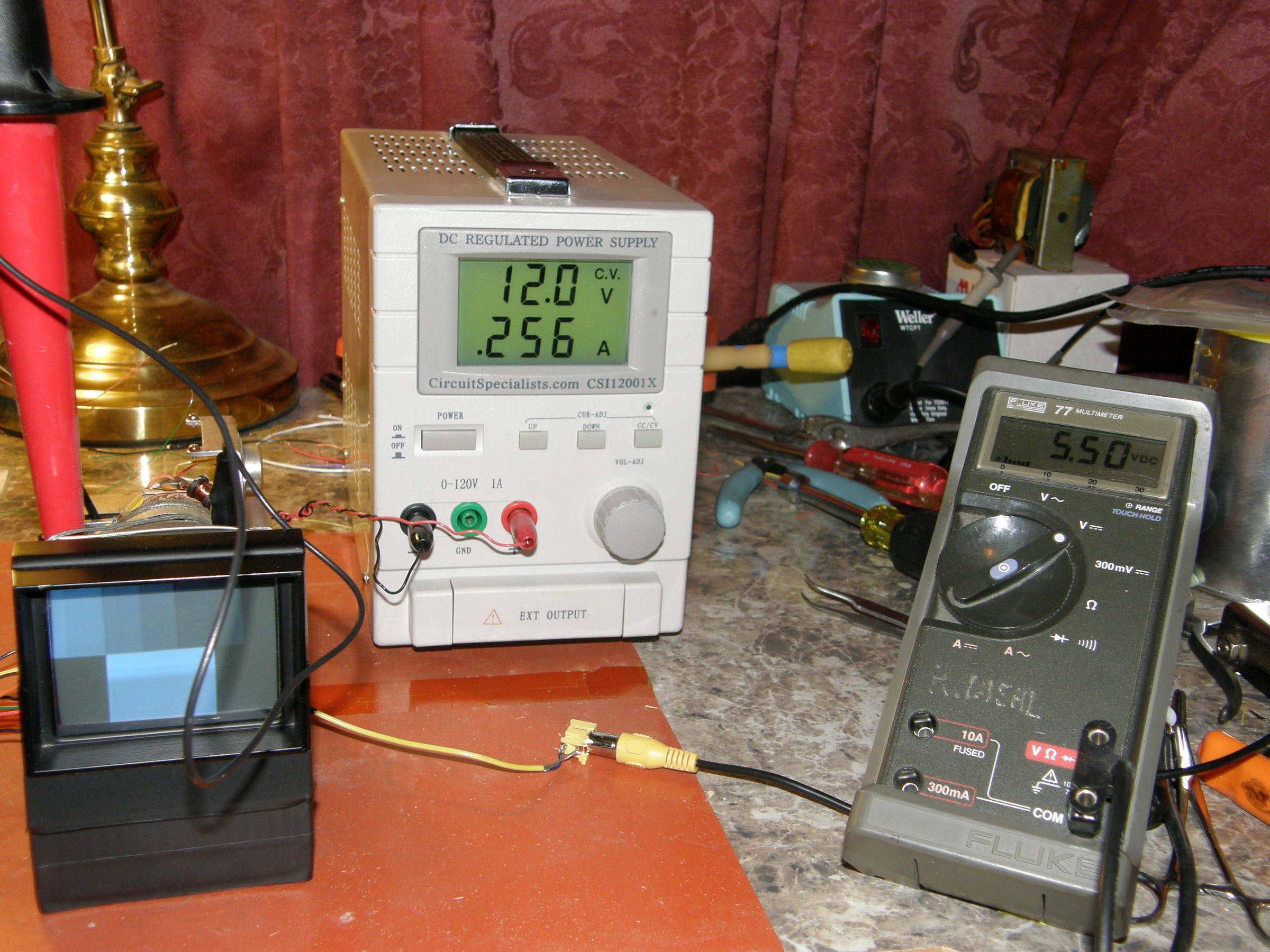
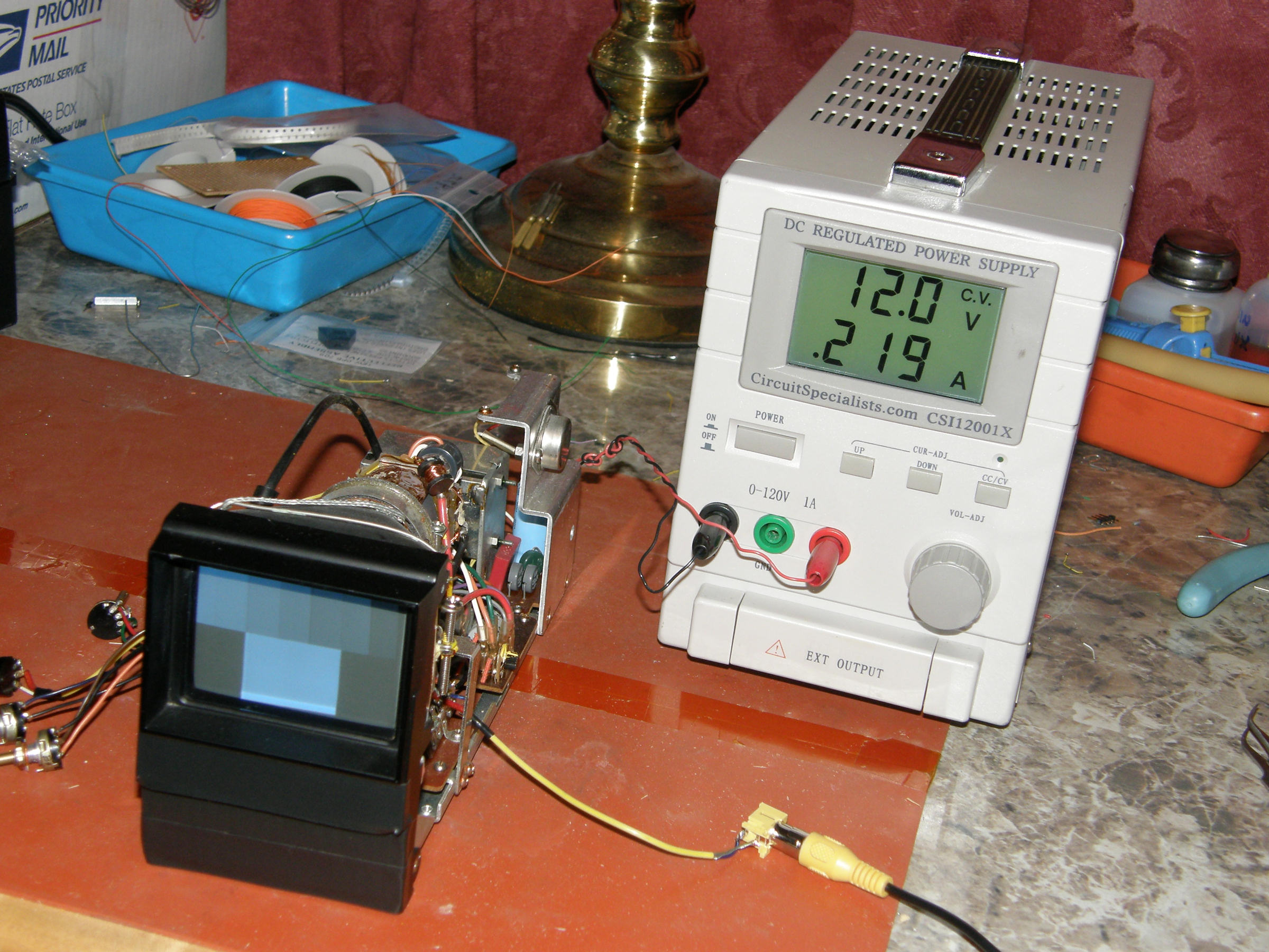
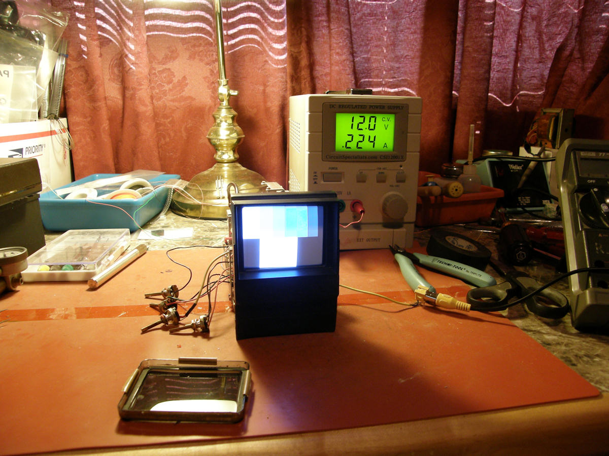
Fluke 80K-6, 6KV high voltage probe and Fluke 77 Digital Volt Meter 20130803 Before we modify this monitor, let's get some base line readings. Input is NTSC color bars with black and white flags. (Actually I/Q/W flags. But, I & Q is meaningless in BW. These are color encoder related signals for standard definition NTSC/PAL/SECAM.) The VM-100 is seen here being powered on +12.0 VDC. Current flow is 225 mA on average. Power consumtion is 2.7 watts. Second anode voltage of the CRT is +5.5 KVDC. Now, when we modify a circuit, we can go back to these readings to determine if anything is changing radically. High voltage was measured with my Fluke 80K-6 6KV high voltage probe and my Fluke 77 handheld DVM. The probe divides the voltage by one thousand to one. 1KV on the tip is 1V at the meter. Base line readings established. DEFLECTION COIL INDUCTANCE 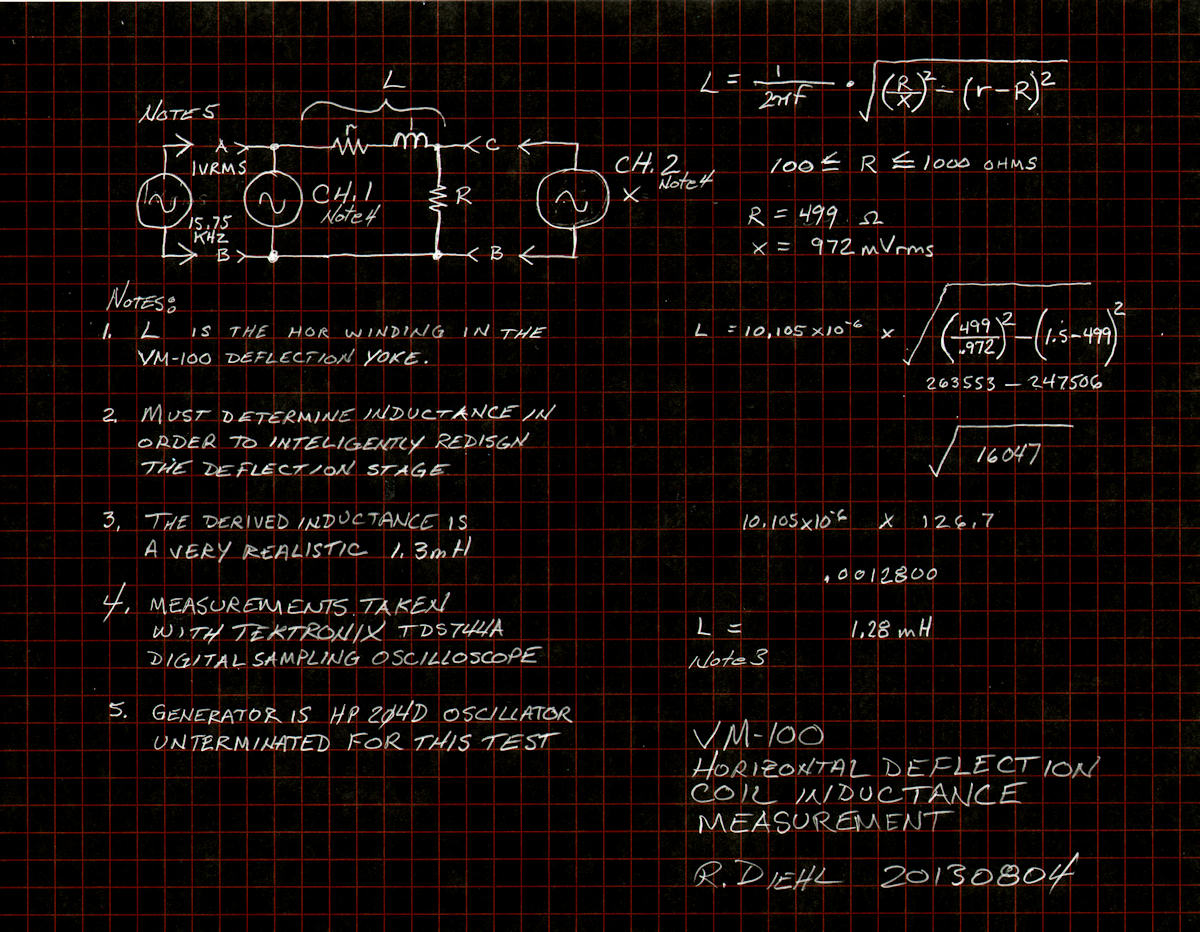
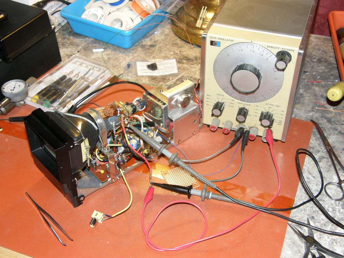
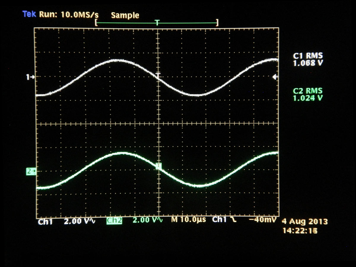
Measuring Horizontal deflection Yoke Inductance 20130804 Today's exercise is to determine the inductance of the horizontal deflection part of the yoke. You just can't redesign a monitor's deflection system without this bit of information. We are skipping the vertical winding as that section seems to be working OK at this time. But, I am planning to drive the horizontal coils separately and allow the original high voltage power supply to run at near original frequency. More about this later. In the mean time, dust off your slide rules boys and girls. We are about to do some algebra. Refer to the test circuit diagram, uppr left of image 1. A generator drives a pure sine wave into a complex network formed by placing the deflection coil (L) in series with a precisely known value resistor (R). O'scope channel one is connected to the input so we can set the oscillator's output voltage precisely to 1Vp-p RMS. O'scope channel two is connected across the resistor (R). We measured the deflection coil DC resistance to get the value little R (r). Little R is 1.5 ohms. Big R (R) is 499 ohms exactly. (Parts are really good these days!) O'scope channel two shows us the value of the voltage across big R. The discrepency between my hand written notes and the scope readings is that the photo was taken at a later time and the levels have drifted. For a deeper appreciation for this test, visit: [A Simple Procedure for Measuring Inductance]. On the right side of my notebook page, is my mathematical work. If you spot a mistake, please notify me. I did the test many times until I started getting repeatable results. I doubt if I could have done this test without my trusty Tek TDS744A digital o'scope. The voltage measurements are actually taken very accurately by the scope! I love it as it removes a lot of the guess work. 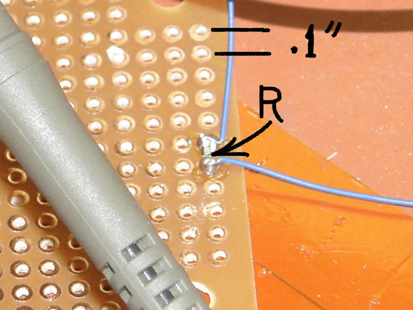
A closer up look at my big R and the removal of the sun shade Have I mentioned how much I like surface mount parts? This is the 499 ohm 1% resistor used for this test. A little awkward to work with. But, well worth it for the extreme accuracy it gives. This proves the old expression, "It's the little things in life that make it all worth while!". Also, along the way, I removed the dark tinted plastic sun screen from over the front of the three inch CRT. This has very likely doubled the available light from the tube. The RBG filter wheel is very dense and can use all the help it can get. During this step, I discovered that the steel frame of the monitor is heavily magnetized and is actually distorting the picture! Will explore this at a later time. The reason we need to know the inductance of the horizontal deflection coil is that we need to get an inductor of that same value to replace the yoke as a load on the flyback transformer. Then we will drive the horizontal coil with a new circuit operating at the CBS rate of 29.16 KHz. The Akai monitor's high voltage transformer will not operate at that, nearly double, frequency. The plan is to divide the CBS horizontal sync by two and drive the high voltage chain with 14.58 KHz. This frequency is within the operating range of the monitor's high voltage power supply. This is my hybrid solution to a sticky high frequency AC problem. What was the final inductance of the yoke coil you ask? Why 1.3 millihenries, of course. This is a real value and I plan to pick up a nice self shielding torroid for the dummy load. I am so confident in my measurements I am going to put this on the inductance meter at work tomorrow to check my work. Stay tuned, the fun never stops. DEFLECTION COIL INDUCTANCE - TAKE TWO 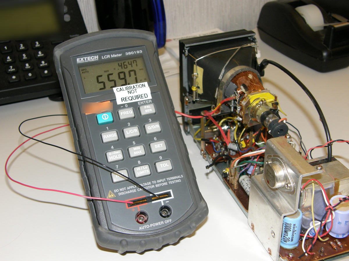
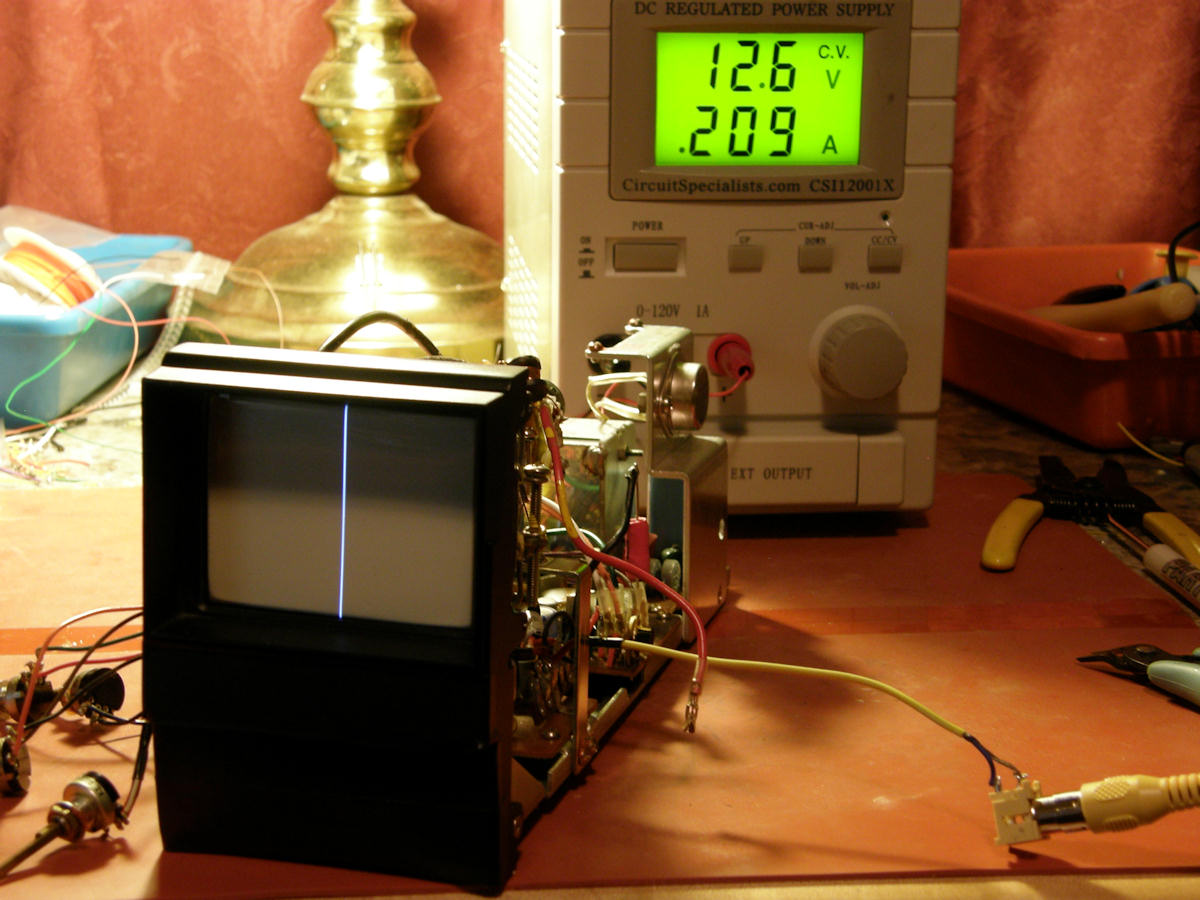
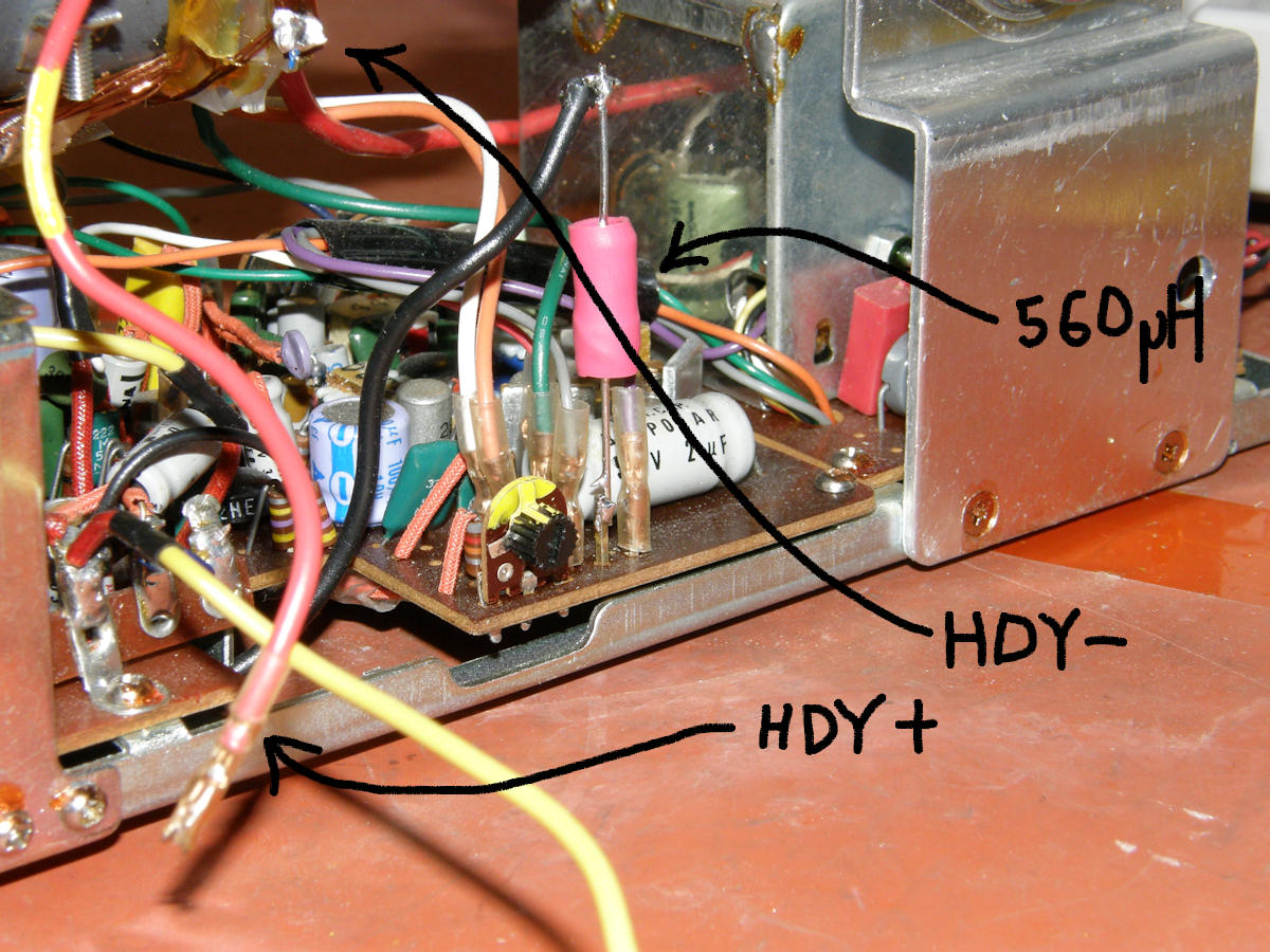
Measuring Horizontal deflection Yoke Inductance 20130804 I proved today why one should always check their work. The infallable digital meter disagreed with my yoke inductance reading from yesterday. It measured the inductance at 560uH (559.7 micro Henries). This is an error of approximately two to one with yesterday's measurements and calculations. Taking the meter's word for it, I replaced the hor. deflection coil with a 560uH fixed inductor. Recall this inductive load is required to stabilize the existing high voltage power supply in the monitor. Hey! Labguy. Are you going to go back and run those crazy measurements and calculations one more time? No. I can do better than that. I placed an order for this identical Extech LCR meter. Model 380193. It will be in my mad scientist hands in a few days. No more guess work with inductors or capacitors ever again. If I'd had this tool from day one, I think we would be viewing color pictures now. Without the yoke loading the HV transformer, the monitor draws 260mA. Efficiency drops and lots of heat usually happens. I set the supply to current limit at around 500mA for safety. With the yoke re-attached, supply current drops to 225mA. This is because, the inductance of the yoke and HV transformer work together to form a resonant circuit. Energy is being rocked back and forth between the inductors (and capacitors) like pendulum. Removing the yoke de-tunes this delicate balancing act.This new 560uH fixed inductor puts it back into tune. As you see in the middle picture, the current is slightly less than normal at 209mA. This is because I have the brightness and contrast turned way down so as to not burn that vertical line into the phosphor screen. Another successs. The HV supply is now independent of horizontal deflection. Please note, that all of this testing is performed with video sync applied to the horizontal oscillator. The testing would be meaningless if it were conducted on a free running, non-synchronous, system. 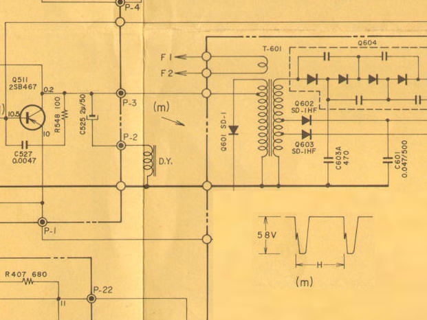
Horizontal output transistor and high voltage transformer with yoke attached The item marked D.Y. is the horizontal deflection coil that is located on the neck of the CRT. That is where our substitute loading coil sits. The item marked T-601 is the high voltage transformeer. Diode Q-601 is the damper. It conducts during retrace time. This dump of enrgy creates the high voltage surge that is rectified by the diodes and sent to the CRT circuits. The wave form in the lower right shows the voltage waveform on the collector of the transistor. The last thing checked was the CRT B+. It was a steady 5.5KV just as in the base line test. From this point on, we can drive the yoke with some other currents and make a crude oscilloscope. Look for a future update along these lines. This is a perfect oppurtunity to try this. It does not interfere with the development of the new horizontal scan board. To recap at this point: We know the inductance of the yoke. We have successfully divorced the yoke from the flyback transformer and the high voltage system. We have not altered any baseline values, nor blown out any components, with the redesign. Over in part 3, at the bottom, is the latest report on the photo tach target I produced with my computer today. [Part 3. COLOR WHEEL] HORIZONTAL SCAN -TAKE ONE 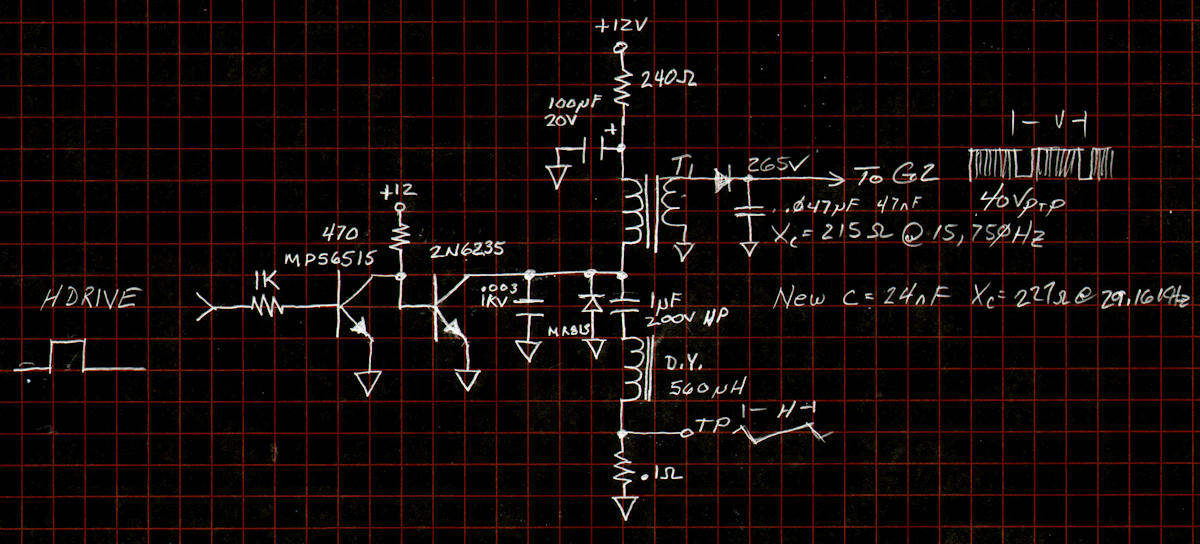
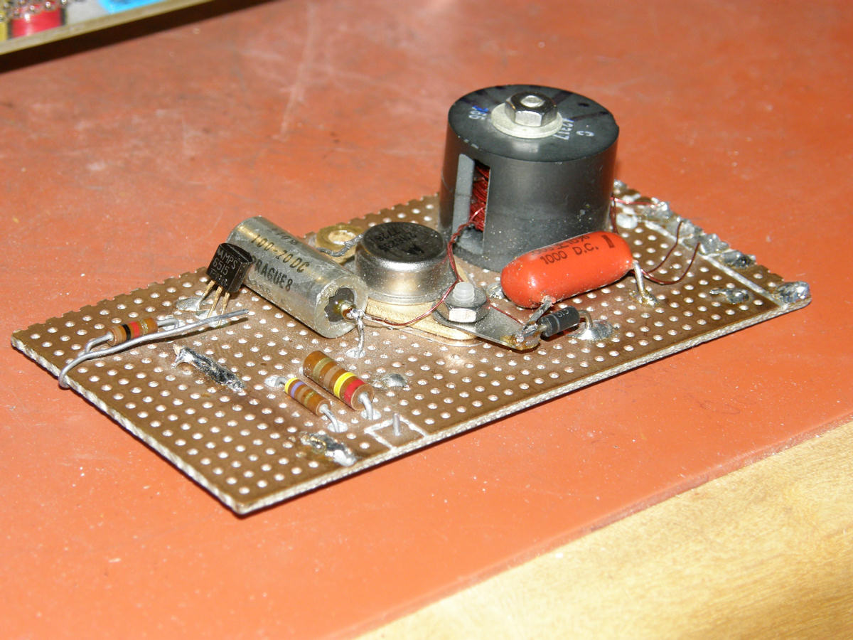
First order version of my scanning circuit. 20130808 Article one. I am starting with a deflection board that was constructed by my good friend, Andrew Mellows, many years ago for a vidicon camera. It has a nice driver transistor and a "wind-it-yourself" transformer core, ready to go. I ran intor Andrew at the DeAnza college electronics flea market last year and pulled this board from a FREE box at his stand. It had a nice vidicon deflection yoke with it as well. Who knows how much of this circuit will be left at the end of this project. So, let's go! As I study the problem of the new deflection system, I keep discovering more 'gotchas'. See waveform (f) on the unmodified monitor schematic, shown above. Turns out, the old flyback supplied the blanking pulses to G2 of the three inch CRT. Since that original HV transformer will be running at a different frequency than the deflection now, that technique will no longer work. So, my new scan board must have a full flyback transformer in order to produce this bias voltage of 265VDC with a blanking waveform of 40Vp-p riding on it. I have always wanted to build a flyback transformer. (bitter sarcasm - far from trivial - fear of the unknown) As seen in the first order diagram, I have added this "bias and blanking" winding to my "hand rolled" flyback transformer. The number of turns on this winding and the value of the filter capacitor will need to be worked out empirically once I get deflection the stage running. I am starting with halving the capacitor value, since I doubled the frequency. The capacitive reactance calculated out to 215 ohms. So, 24nF gives me roughly the same value at 29.16KHz. But, 22nF is a real value and even closer to 215 ohms. Also, notice the 0.1 ohm current sensing resistor in the bottom leg of the deflection yoke. This provides a convenient point for observing the yoke current waveforms on the o'scope. 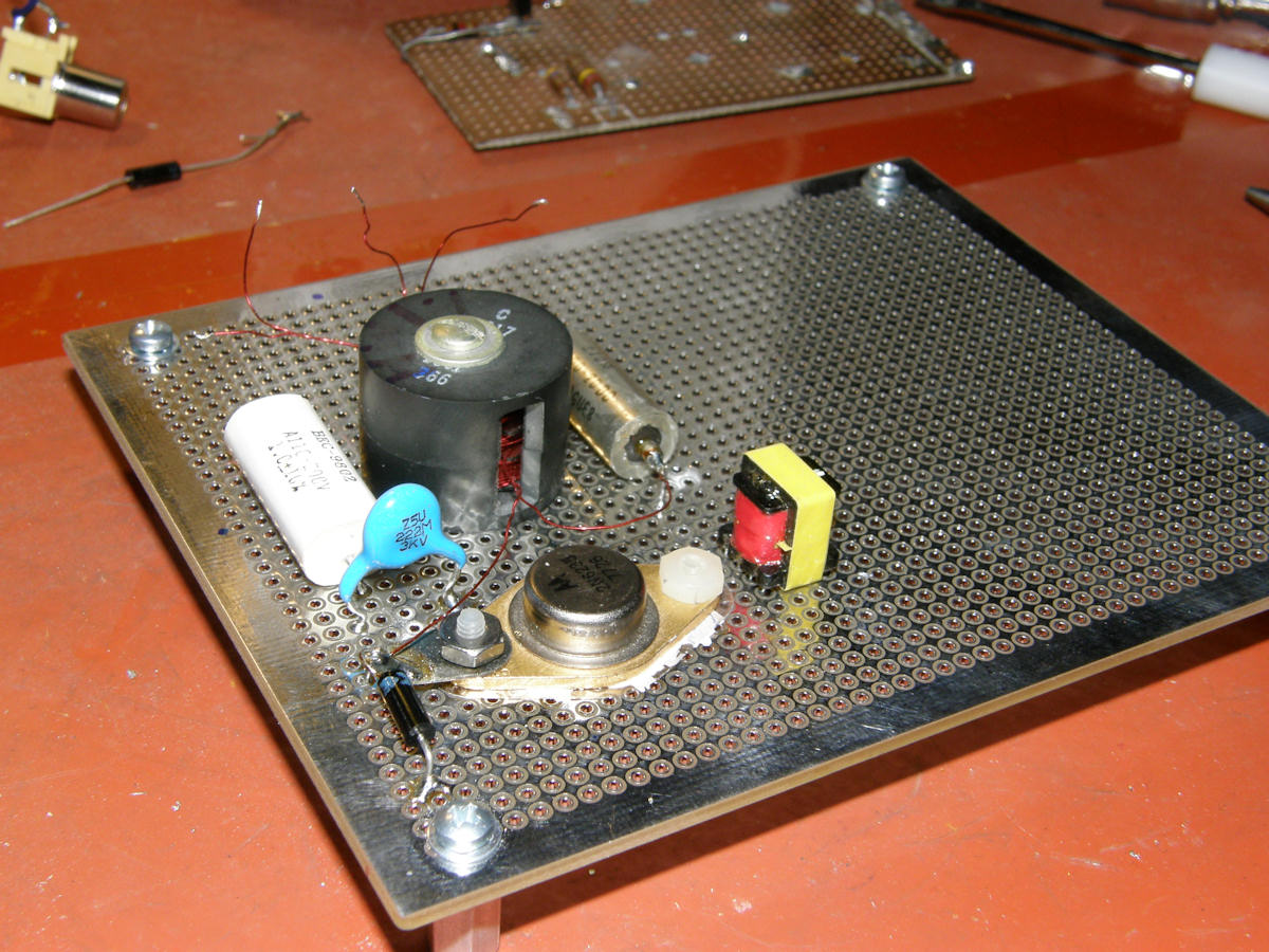
Beginning construction of new 29.16KHz horizontal deflection board 20130808 I have begun moving parts from the old PCB to the new. I have decided to add a coupling transformer between the input buffer transistor and the output transistor. I have copied plenty of deflection circuit designs and this is starting from another's design. But, from this point forward, it becomes my design. As I am absolutely certain this is not the final word on the subject... This board will also include an LM1881N sync separator chip. The comp sync will be processed to H sync and fed to the scan blocking oscillator, yet to be designed. Timers(digital one shots) will be used, just like on the servo, to set pulse widths and positions accurately. In addition, there will be the H Sync divide by two circuit that drops the 29.16KHz sync down to 14.58KHz to drive the flyback high voltage back on the monitor main chassis. The new L/C/R meter arrived today. What a neat piece of gear! Also received some inductor samples from Coilcraft to try out as well. 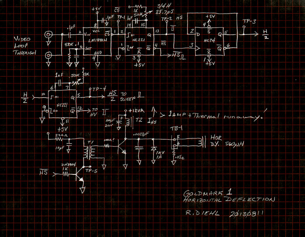
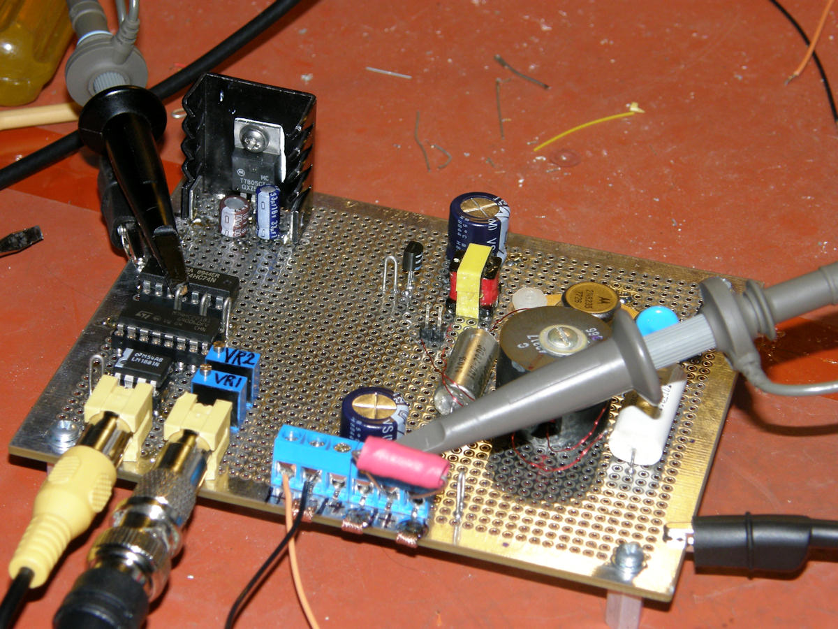
First smoke test of the 29.16KHz horizontal deflection board 20130811 Spent the weekend doing general clean up of the mechanical design and then got down to serious work, assembling the horizontal scan board. I constructed the pulse processor section first. This separates comp. sync from video, separates H. sync from the composite sync, divides the H. sync by two, produces a fake half-H rate sync pulse for the flyback transofrmer in the monitor, and finally drives the horizontal scan driver at the full 29.16Khz. Pulse processing section constructed and tested successfully. The horizontal output is doing what one would expect. Pulling huge amounts of current, generating vast amounts of heat and not deflecting anything. Stay tuned as I sort out this latest pile of issues. If you have any practical experience in magentic deflection circuit design, please contact me. Here are the open ended questions currently on my mind: "How do you debug this circuit without it burning to a crisp each time it is powered on?" "Will running with a current limited supply effect the dynamic operation of these circuits (supply impedance effects)?" "Is there a target impedance of the transformer, yoke, or both, to start from?" "Is the circuit tuned to resonance or anti-resonance? Is only part of the circuit (anti)resonant?" 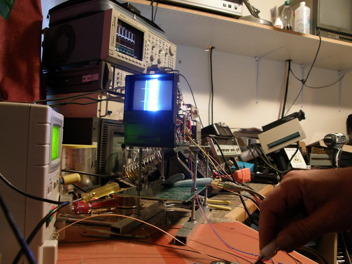
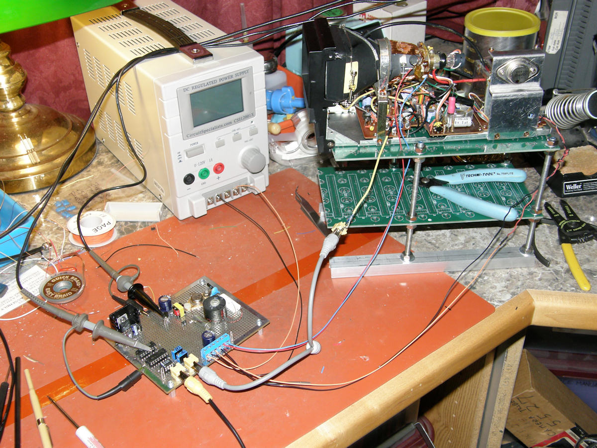
First scan yoke test of the 29.16KHz horizontal deflection system 20130811 After experimenting with placing series resistors into the base of the horizontal output transistor, I got the supply current down to below 100mA. But, the circuit still tends to go into thermal runaway. I have the power supply set to hard limit at 1 amp. My board gets hot. But, nothing has failed yet. I decided to be bold. Hooked up the horizontal deflection yoke to my board and wired up power and video to the CRT monitor. It was a full head's up test, folks. No smoke! Half a screen width of folded over horizontal deflection. I'd say that's a great start for shooting blind in the dark. Next step is to figure out how the inductances and capacitances all relate to each other and to the scanning frequency. Never give up! Never surrender. This was the first time that I have ever driven a CRT deflection yoke with a driver circuit of my own design. Stay tuned. The fun never stops! 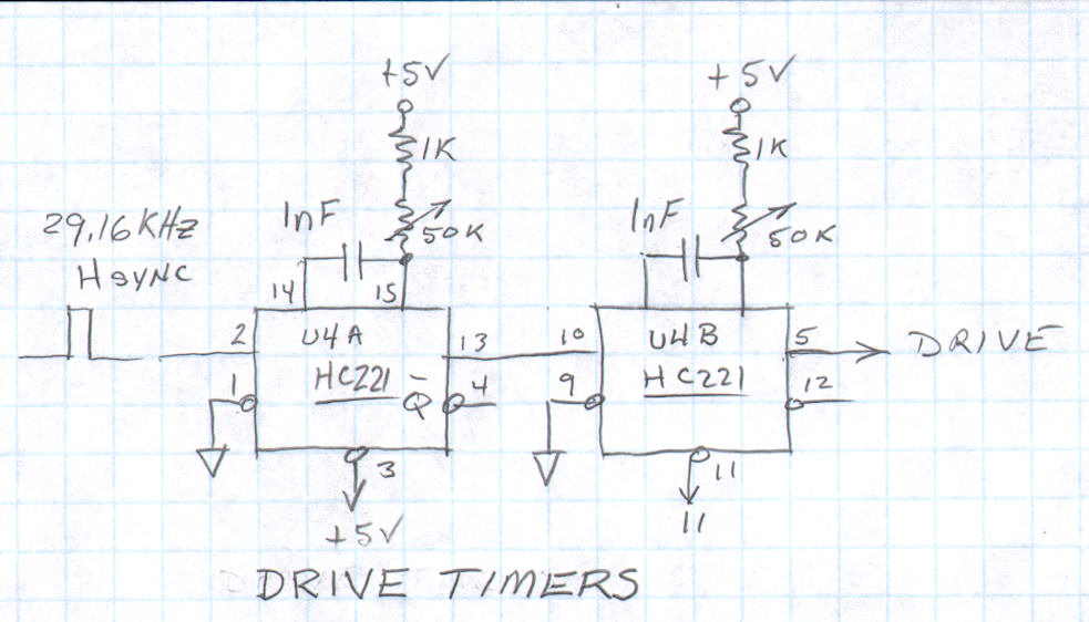
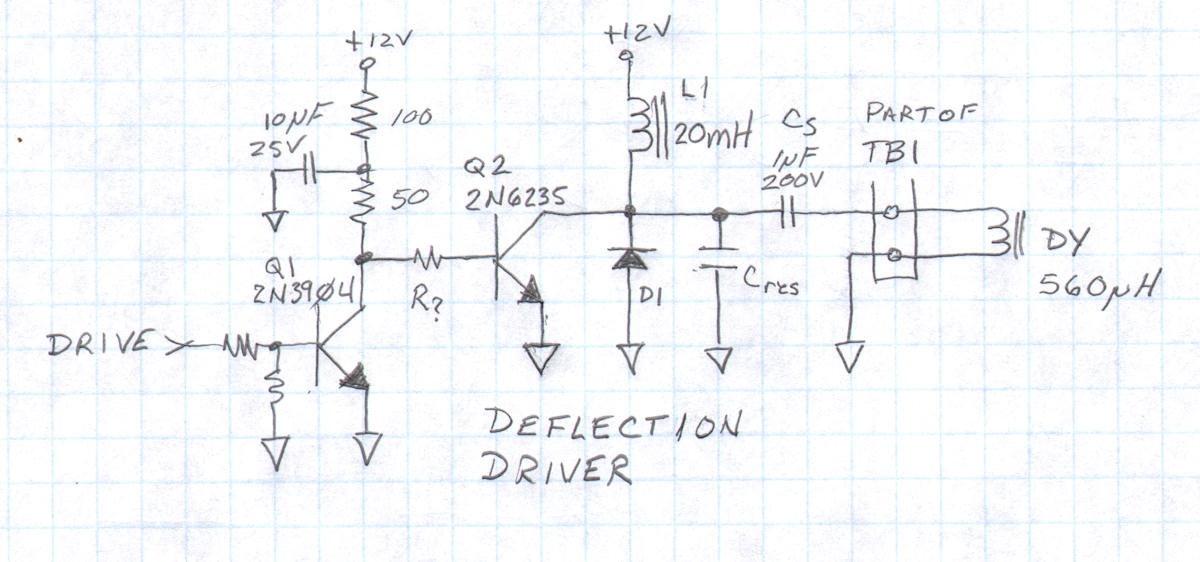
Horizontal deflection system (re)design two rough schematics 20130815 I'd like to officially thank Kevin Hempson for his invaluable assistance with this project. Kevin's guidance and insight into horizontal scan circuits is very much appreciated by this Labguy. Thanks also to Cliff Benham for his guidance on color wheel construction and servo properties. His predictions were spot on. Let me tell you this, designing scan circuits is fun folks. But, "it sure ain't simple!". The word I grope for is, "challenging". To help in this respect, I have to admit spending significant thousands of dollars in the past thirty days to tool up correctly for this project. Ouch! Today, I added a new current probe and a 100X voltage probe to my new Tek TDS-744A digital sampling oscilloscope. Another five hundred bucks plus change! The current probe is almost mandatory for inductive design work. Most of the energy's information that we need to see is conveyed in the current and not in the voltage. In fact, looking at these circuits in the voltage domain reveals extremely complex or almost chaotic waveforms. With deflection coils (huge inductors), the scanning ramp is viewed in the 'amps' domain as compared to measuring the scan ramp in volts - as in the case of electrostatic deflection. The next ah ha! moment I had was when I started to control the output transistor's base current. This had enormous effect for moderate changes. Unlike the effects I am currently getting in attempting the achieve a resonant frequency around 100KHz. However, even with the capacitor, Cres, removed completely from the circuit, we are not seeing a working waveform. I performed several iterations of the calculations and took the capacitor value down to 10pF and could only get resonance up to 68KHz. It needs to exceed 100Khz at an absolute minimum. The problem may be that the deflection coil has too much inductance and can never resonate at a the frequency we need. I fear this means the yoke must be dismantled and windings removed from the horizontal coils without damaging anything else. Yikes! I am removing the interstage coupling transformer. This device was giving me grief because of the high voltage spikes and ringing it generates. I am replacing this with a simple inverting single transistor buffer (2N3904). In front of this driver, are two one shot timers which will allow me to control the output transistor base on/off times absolutely. I expect to use a series resistor and/or other passive network for the final tuning of the base circuit. I have a much higher confidence in this approach than the previous version. This does not mean this version will work. But, if not, we will just be that much smarter. 201308151515 PROJECT UPDATE JANUARY 4, 2014 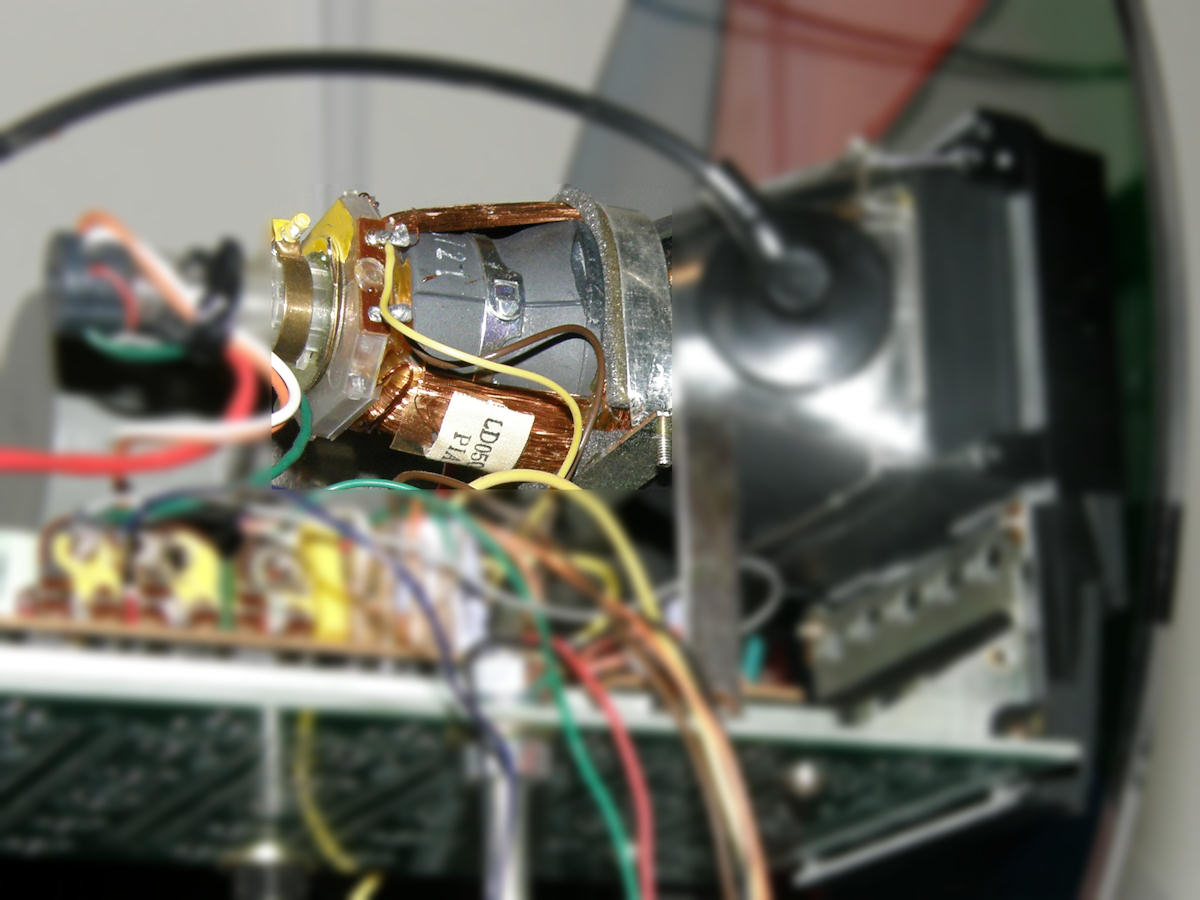
Three inch CRT deflection Yoke I have studied my circuit and the components over the holidays. I am working from a manual produced by Philips Electronics for video monitor designers. It covers the design of high power, large color CRT, deflection in great detail. It includes the details of every form of scan distortion imaginable. Primarily for computer monitor designers. I will settle for just scanning at this time! As a result of the careful study, I discovered one measurement I had overlooked. I performed it this morning. I wired the horizondal deflection yoke in series with a 62 ohm power resistor, an ammeter and a variable DC power supply. I turned on the monitor and got the vertical line on the screen produced when there is no deflection current in the coils. I then slowly raised the voltage, and thus the current through the yoke, until the vertical line touched the side of the CRT. I did this in both directions, having to reverse the PS polarity. The result is that this deflection yoke requires +/-400mA for full deflection. This was a critical piece of missing information. So, here is what I now know about my defelction yoke coil. It has a DC resistance of 1.5 ohms. It has an inductance of 560uH. At 29.16KHz, the inductive reactance is 102.6 ohms. The deflection coil requires bipolar 400mA to scan full screen width. At least at zero rate of change, DC. Since the Philips manual recomends a BU2508D power transistor with built in damper diode, I have ordered some of these parts on Ebay. They appear to be out of production. Just the way I like it! Vintage parts for vintage tech. [HOME] [ELECTRONICS PROJECTS] [GOLDMARK 1, TOP] [GOLDMARK 1, PART 8] Created: July 27, 2013, Last updated: January 4, 2014 |