|
LabGuy's World: 'Goldmark 1' - Field Sequential Color TV Project
PART EIGHT: Putting it all together now. 
Monitor and color wheel meet for the first time! 20130804 After growing tired of the electronics, I took up asssembling the monitor platform. I used a scrap bare circuit board for the platform and four, quarter inch, threaded steel rods for upright supports. A couple of half inch C channel extrusions make up the mounting base. These will eventually be screwed to the baseboard. The platform can be adjusted up and down over a large range. This design allows leveling the platform both front to back as well as side to side. I will set it with an engineering rule in the final assembly. There will be a second platform to hold the new horizontal deflection board as well. And, finally, there will be a second support stand unit, just like this one, on the other side of the motor, to support the servo board and, possibly, the Aurora World Converter. The power supplies will be placed in the center, standing on edge to conserve space. It is very elegant when it is finally fitted together. 
Another view of the BW video monitor behind the color wheel All of this new surface area will get painted flat black. Just like the motor mounts. The face of the CRT is completely covered by the color wheel shading it from light intrusion now. The screen sits at the back of a short jet black tunnel which should give the best contrast. The way this is finally coming together is very exciting! More to come. 

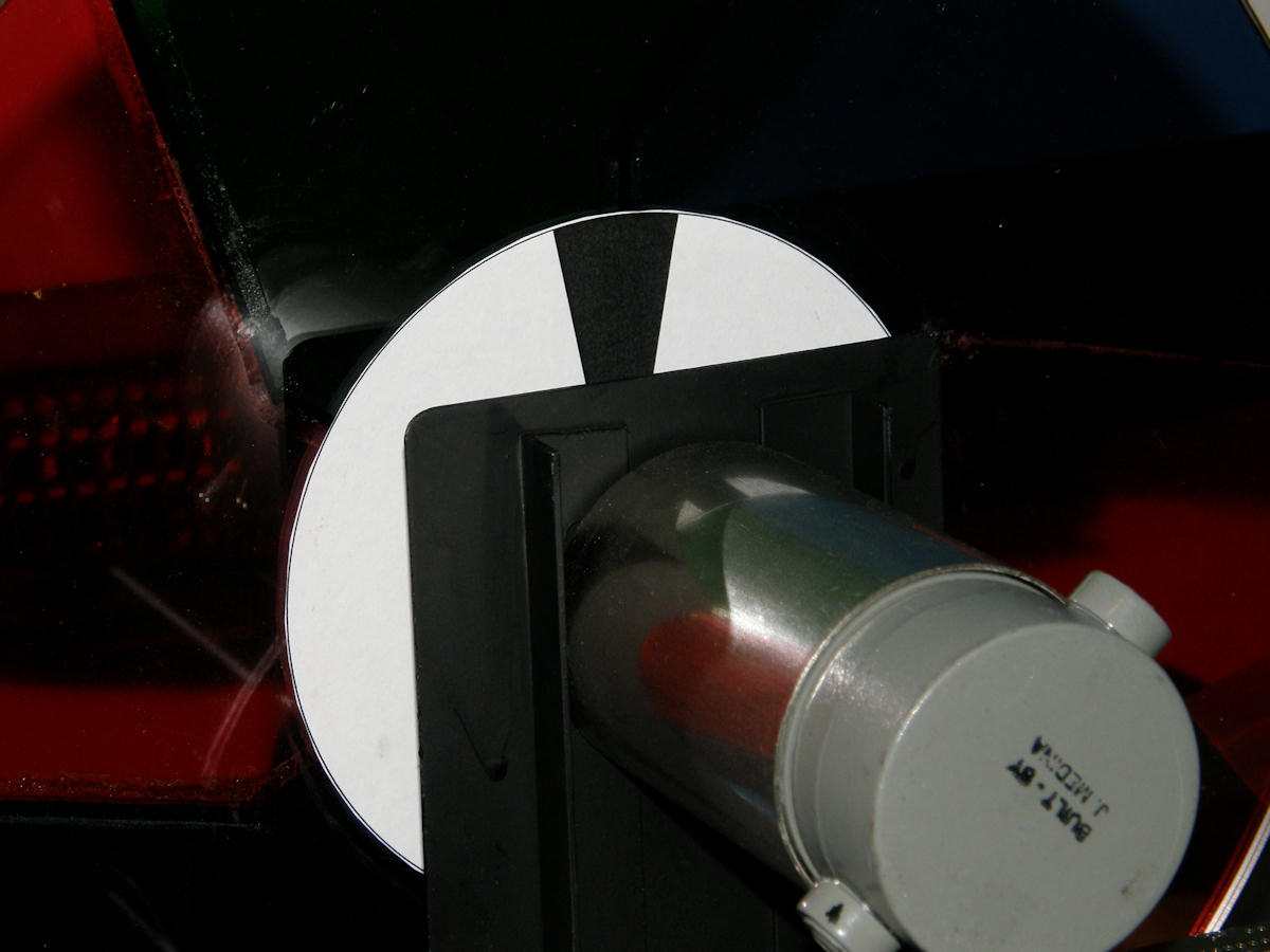
Mechanical construction progress as of 20130811 Finally got around to mounting the pots that have been dangling out of the CRT monitor for the past seven weeks. Miraculously, we did not break any wires during this phase. Finalized the base of the support stand. Increased the width of the C channel aluminum to accommodate the 1/4" nuts used to secure the threaded rods to the base board. The monitor support stand is made of used circuit board, 1/4"-20 threaded rod and half inch C channel rails, plus assorted nuts and washers. The top shelf supports the Akai three inch CRT monitor. The middle shelf supports the new horizontal scan board, currently undergoing construction and debug. The center photo is of the CRT monitor fitting session. The CRT is at the extreme left side of the wheel, peering through the red filter. It is gratifying to see that the final product resembles my orignal concept drawing so closely. Also, notice that the servo tach (paper) disc is visible and making the RBG filters "pop" in the center. The right hand photo shows the back side of the tachometer feedback disc. The next phase of the servo part of the project will be to construct the appropriate mount for the photosensor. [HOME] [ELECTRONICS PROJECTS] [GOLDMARK 1, TOP] [GOLDMARK 1, PART 8] Created: July 27, 2013, Last updated: August 11, 2013 |