|
LabGuy's World: PHOTOMULTIPLIER TUBES
Project Start - 20141128 PROJECT GOAL: Study the characteristics of photomuliplication in preparation for construcing both an Image Dissector Tube video camera and a Color Flying Spot scanner for 35mm slides. 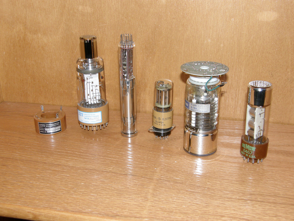
Five photomultiplier tubes and support devices - 20141128 There are two types of photomultiplier tubes. Imaging tubes and non imaging tubes. Here are examples of both. In this first photo are five different tubes utilizing the secondary emmission of electrons for signal amplification. From left to right; IT&T FW-130 steerable photomultiplier tube and deflection coil, IT&T Image Dissector - type unknown (F4012?), General Electric 1P21 side view photomultiplier, EMI 9750T five centimeter diameter end view photomultiplier with support circuit board, and a DuMont one inch end view photomuliplier tube. The photomultiplier was not invented by Philo T. Farnsworth. But was highly developed by him to obtain the necessary enormous gain required by the dissector tube camera operating at television rates. The principals of the tube are simple. A photon strikes a chemical coat on the inside of the glass envelope and knocks electrons free behind it. This coating, the photocathode, is typically held at an extremely high negative votltage of between 500 and over several thousand volts depending on the tube and application. These freed photon induced electrons are located in a region called the drift zone. A screen at the far end of the zone has a positive voltage applied to it, relative to the photocathode voltage. Usually between 20 and 100 volts. The electrons begin drifiting (90,000 miles per second or half the speed of light) toward the screen. Behind the screen is the first dynode. It is about 100 volts more positive then the screen. Because the dynode is solid metal and the screen covers virtually no area, most of the electrons zoom right through the screen and strike the dynode. These elctrons, in turn, strike off more secondary electrons which are now attracted around the corner to another cleverly placed dynode that is, you guessed it, 100 volts more positive than the one behind. This cascading multiplying effect continues until the much amplified signal reaches the anode which is at zero volts. But, still 1000 volts more positive than the photocathode. The output signal is developed by running the anode current through a high value load resistor and picking off the signal voltage developed across the resistor. Under the right conditions, a single photon can saturate the output anode. That is to say the anode is giving up every single electron available, even though there may be more signal trying to come through. In the most extreme cases, the anode or the load resistor can be burnt to a crisp by a single photon at the input. This is the upper limiting factor in a photomultiplier tube gain. 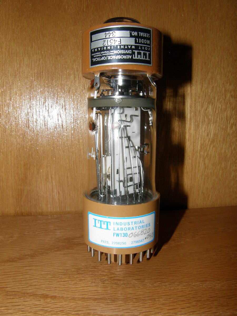
IT&T Steerable photomultiplier tube with deflection coil - 20141128 The IT&T FW-130 steerable photomultiplier tube. Not quite an imager (or is it?), the FW-130 is able, with the assistance of the deflection coil, to determine which direction light is coming from. It was used in a star tracker navigation system of a spy satellite. That is very cool! Cryogenic, in fact! I received this tube and a cryogenic chamber that contained it. (Need to find a project for this device. A 30 second beer chiller perhaps?) I have complete circuitry and info for the operation of this tube. I just don't have the particular details for this exact tube.... yet! At IT&T, each tube was semi-custom made to customer specifications. They probably sold vast quantities of... several, at a time! To say these could be rare is an understatement. If you have inside knowledge about the manufature and uses of these tubes, please feel free to drop me a line. Documentation would be greatly appreciated as well. [EMAIL] Examining the markings on the tube, I see the number, ".040". Could this imply that the aperture is 40 mils? If this is the case, this tube could be an imager of a reasonable resolution. The part of the tube that the deflection coil is sitting upon is called the drift region. In this tube, the secondary electrons from the photocathode are collimated by an electrostatic field. This means that an electron image, of the scene focused on the target will be reproduced in the drift region. This entire virtual image is swept back and forth over the aperture to sample the pixel locations. More on this process later. 
Unidentified IT&T one inch Image Dissector Tube and deflection / focus coil - 20141128 (NOTE. The tube in the photo is not curved. That is spherical abberation in my digital camera from using macro close up.) This is an unidentified IT&T one inch image dissector of the F4012 family. I have extremely limited documentation, and various articles, defining the family of dissector tubes made by IT&T. Unfortunately, this tube does not fit the exact description of any of them. I did glean enough information to eye ball the pinout of the tube and get a very good idea of how to bias it to operation. This is my primary Image Dissector Video Camera candidate. The aforementioned FW-130 may have just enough resolution to make a Logan Baird format 30 line dissector camera. Wouldn't that be cool? The one inch dissector tube has the final excellent advantage that it will operate in the deflection yoke for a one inch vidicon tube, shown behind the tube. Awesome! Note how this tube has a much longer drift region. It also uses magnetic collamation to form the electron image within the drift tube. This is accomplished with the "focus" coil of the vidicon deflection yoke. The two major unkowns with this tube are its spectral sensitivty and the aperture size. If I have "eye balled" this thing correctly, the aperture is about one twentieth (1/20) the width of the photocathode. This is not good. That would imply about 30 to 40 lines of resolution. Then there is the spectral sensitivity, it could range anywherre from deep infrared to the ultraviolet. For what could I use an ultraviolet sensitive camera that won't render me blind from UV cornea damage? I am going to proceed on the assumption I am wrong on both counts. By the way, an ultrviolet sensitive dissector tube is extremely useful in astronomy. Never point one into a motel room! (A little tasteless humour and snark for those who "get it"!) 
GE 1P21 nine stage photomultiplier tube of the type 931 family - 20141128 This is the tube we will be experimenting with first in this project. The 1P21 is a classic nine stage photomultiplier of the RCA 931 family. Moving right along... 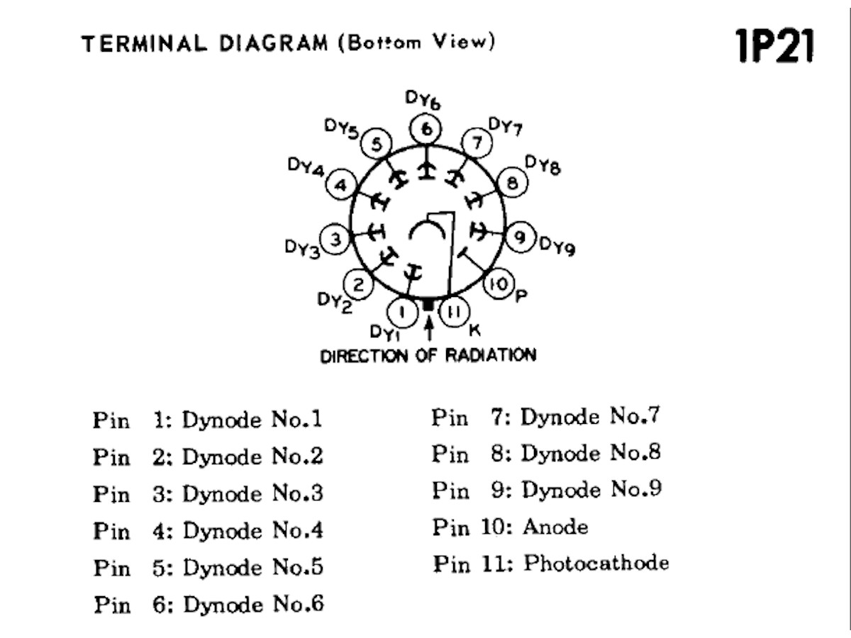
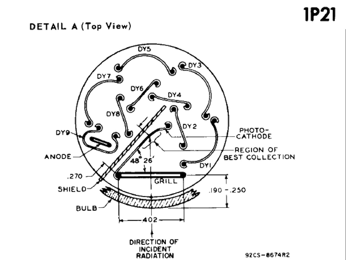
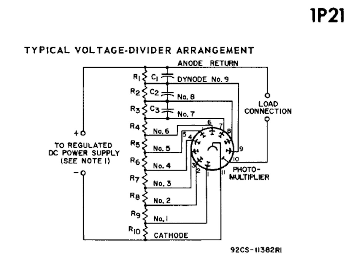
From the RCA datasheet, the 1P21 in detail - 20141128 ...let's look at this tube in detail. (FYI: Cathodes are negative and anodes are positively charged.) Unlike the image dissectors, this tube's photo-sensitve cesium-antimony coating is on a metal plate instead of on the glass. In the center diagram, the path of light into the tube is shown. It strikes the photocathode plate and knocks off secondary electrons. These electrons are forced to the right by electrostatic forces between the various electrodes. The spray of electrons from the photocathode are directed into the cup shaped DY1 or dynode one. Again, secondary electrons are induced. These are repelled by DY1 and attracted by DY2 which is charged more positive than DY1. This process proceeds around the dynodes until reaching the anode. The schematic shows how simple the circuit is for biasing this tube into operation. The positive terminal of the high voltage power supply is the real system ground. This is so that the anode of the tube is at near zero volts so that we can couple it directly to a transistor or even the input of an opamp! In the next few days, I will build the circuit shown in the right most diagram. I plan to try various load resistor values to see what the effect is. The tube will be operated at several voltages between 300 volts and 1,200 volts. Stay tuned! 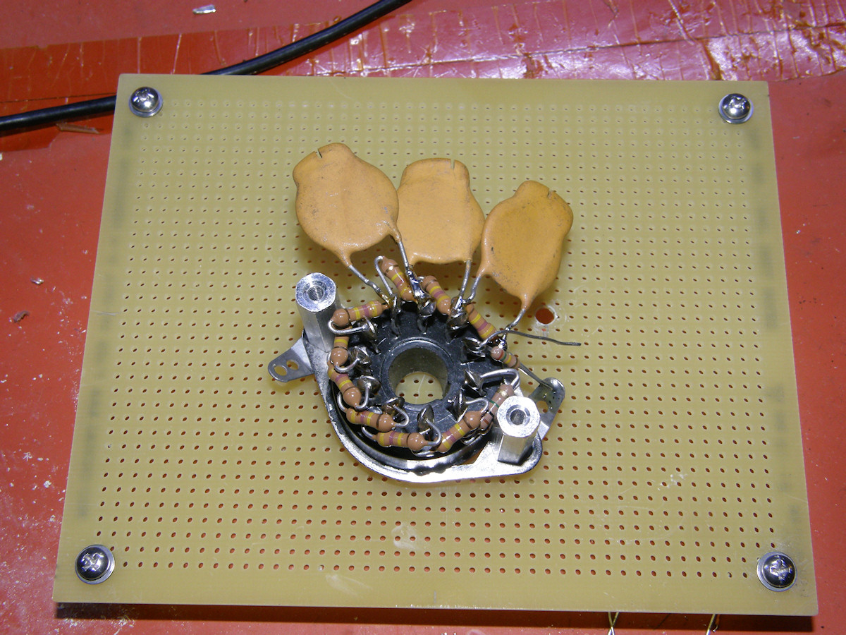
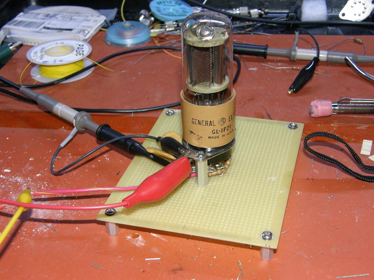
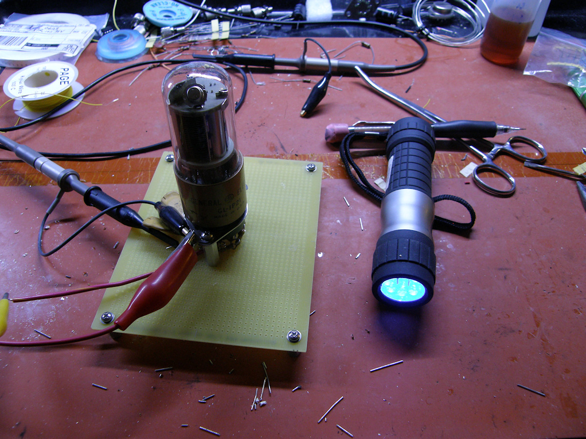
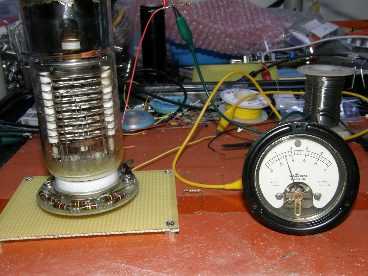
Construction and testing success! - 20141128 That was easy for a change! It took about an hour to construct the test aperatus. An eleven pin variant of an octal tube socket, wired with ten resistors in series and three bypassing capacitors. The resistor values are all 470K with the exception of R10, as shown in the schematic earlier. This one resistor is made of two 1M resistors in parallel to give me 500K. I only had 9 of the 10 required 470K resistors. 500K is close enough to 470K for this test. An error of only 6%. Not great. The 470K resistors are 10% tolerance already. So, in theory some of them could be greater than 500K and still be within the 10% tolerence. Ten percent tolerence of a 470K resistor works out to a range of 423K to 517K. That is how junk box electronics is done! The Anode load resistor is 150K ohms and goes to ground. Not wanting to destroy the PMT, I started with a very conservatively low voltage of 340 volts. The gain of the tube is proprtional to the voltage across the divider resistors. Using a 100:1 probe on my oscilloscope, purchased precisely for testing high voltage vacuum tube circuits. With low illumination the output voltage is around zero volts. Using my UV flashlight, because photomupltipliers are frequently very blue sensitive, saturation occured at around -50 volts DC. Proportional amounts of light, produced corresponding voltages. Sweet! I always knew this part would be easy. The photomultiplier is a complex component that is relatively easy to apply. These experiments are designed to collect the information and experience to move forward on the Image Dissector video camera and the color flying spot scanner. Both use photomultiplier tube principles. Future experiments will zero in on the appropriate load resistor value to give us around a 10Vpk signal over the full illumination range. Expected trade off's are gain vs frequency response. We will need both for the dissector camera and the flying spot scanner for sure. 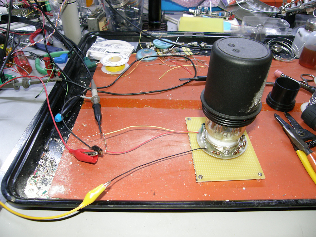
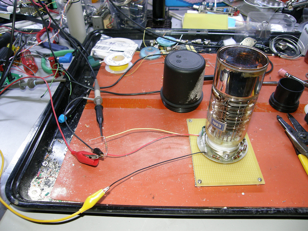
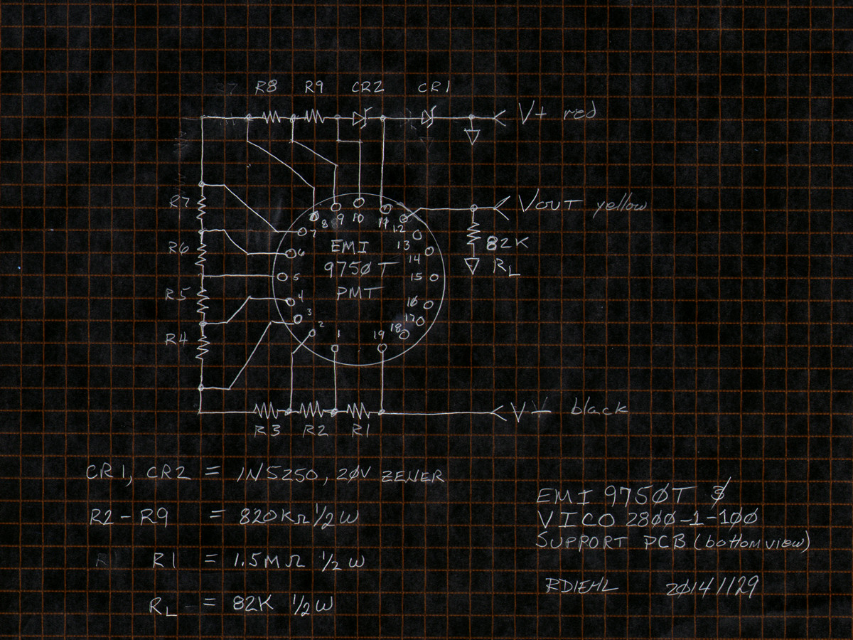
Testing photo tube number two, an EMI 9750T with support PCB - 20141129 I wired up the EMI end view photomultiplier tube, type 9750T on a support PCB of type 2800-1-100 made by VICO this morning, and gave it a go. What do you know? It works too! Operated the tube and divider on 340 volts, with an anode load resistor value of 82K ohms. Output voltage swing; No light = 0V and full UV illumination on the photocathode (saturation) gives a nice and strong minus ten volts. Another success! I really needed to verify that yesterday's easy success was indeed what it appeared to be. And it was. This is extremely encouraging. What have we learned up to this point? The lower the value of the anode load resistor, the lower the signal voltage swing from total darkness to PMT saturation. The anode outputs a current porportional to the amount of light falling on the photocathode. So, by discovering this maximum current, it is a simple matter to calculate the correct load resistor for the signal voltage swing that we desire. Let's see what the output current was at saturation for these two photo tubes, operating at 340 volts. First, the 1P21. Vsat was 50V into a 150K ohm resistor. Ohm's law tells us the saturation current Isat was 50V / 150,000 = 333uA. One third of a milliamp? That sounds like a real number to me. Next, let's check the EMI tube. 10V / 81,000 = 123.5uA. Again, this sounds awfully close to 125uA or one eighth of a milliamp. Reverse engineering at its finest. More testing to come! I'm going to take a wild guess here. My little 340 volt power supply is approximately one third of 1KV or one quarter of 1250 volts (very roughly). Notice that using these factors, and assuming the gain scales linearly, both tubes are operating in the 1mA output range at approximately 1,000 volts. Very interesting. Is 1mA (0.5mA at 1KV for the 9750T) a typical output current when these tubes are at the correct operating voltage? Does the 9750T operate at .5mA at 1KV or perhaps 1mA at 2KV? Something for us to think about. 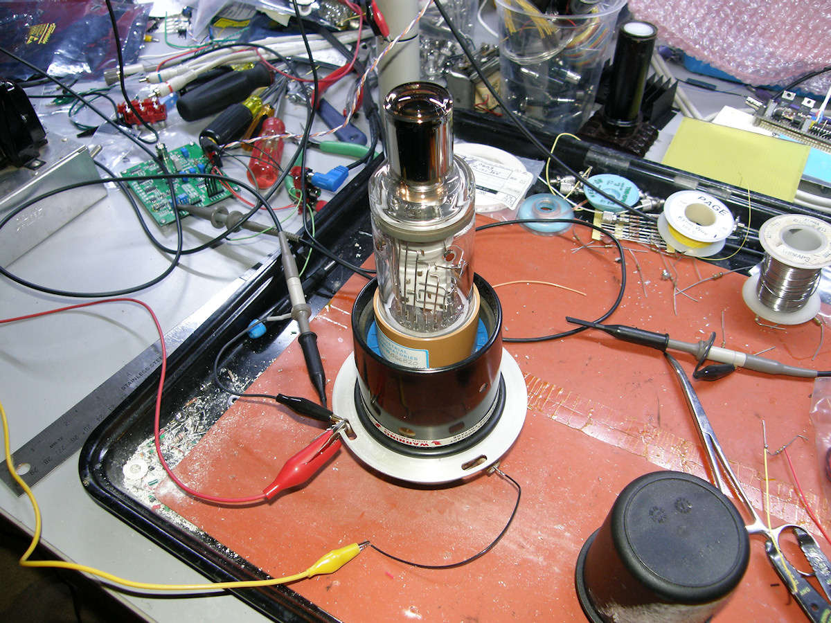


Testing photo tube number three, an IT&T FW-130 and matching divider array - 20141129 This is the first use of my laboratory high voltage power supply. I hooked up the FW-130 to the 340V supply and it barely operated. The output was a mere 200mV. So, I moved it over the Leybold variable high voltage power supply. Dialed it up to 1,000 volts and tried the FW-130 again. Success, of course. The base unit contains the electronics and is clearly marked to operate on 1KV. So, I powered it up and dumped the anode output into a 1M ohm resistor and now measure 0 volts to -50 volts going from total darkness to saturation. Not to shabby! That's three successes in a row. For measuring the high voltage, I used my Fluke model 80K-6 high voltage divider probe and trusty Fluke 77 multimeter. The probe divides the voltage by 1000:1. The probe has a maximum input of 6 kilovolts. You can just see that the high voltage is at 1,035 volts in the center photo. The meter reads 1.035 volts, which is the 1000:1 scaled voltage reading. 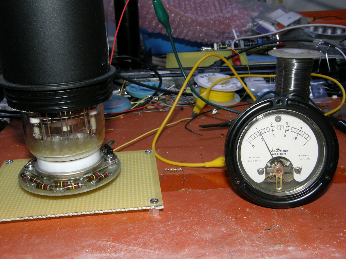
Measuring the EMI 9750T output current at 1KV - 20141129 Running this tube at 1KV, the gain is so high that I can not get a true zero output in room light now. The little black cup is not doing the job. Too much light is coming around the bottom and up through the glass. You can see that the anode current is running at 200uA with the cover on the tube and about 300uA in the light. I suppose it is time to consider constructing some sort of light tight testing enclosure. 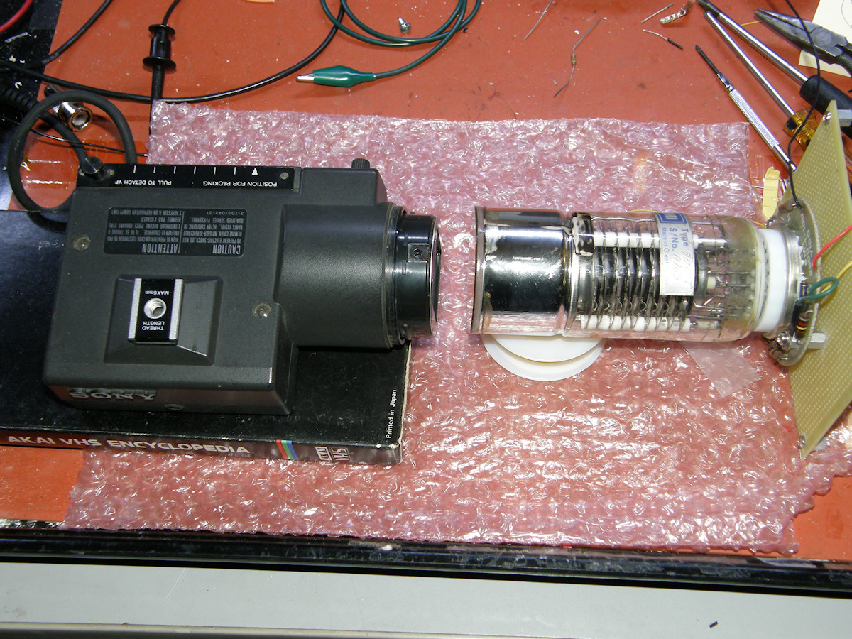
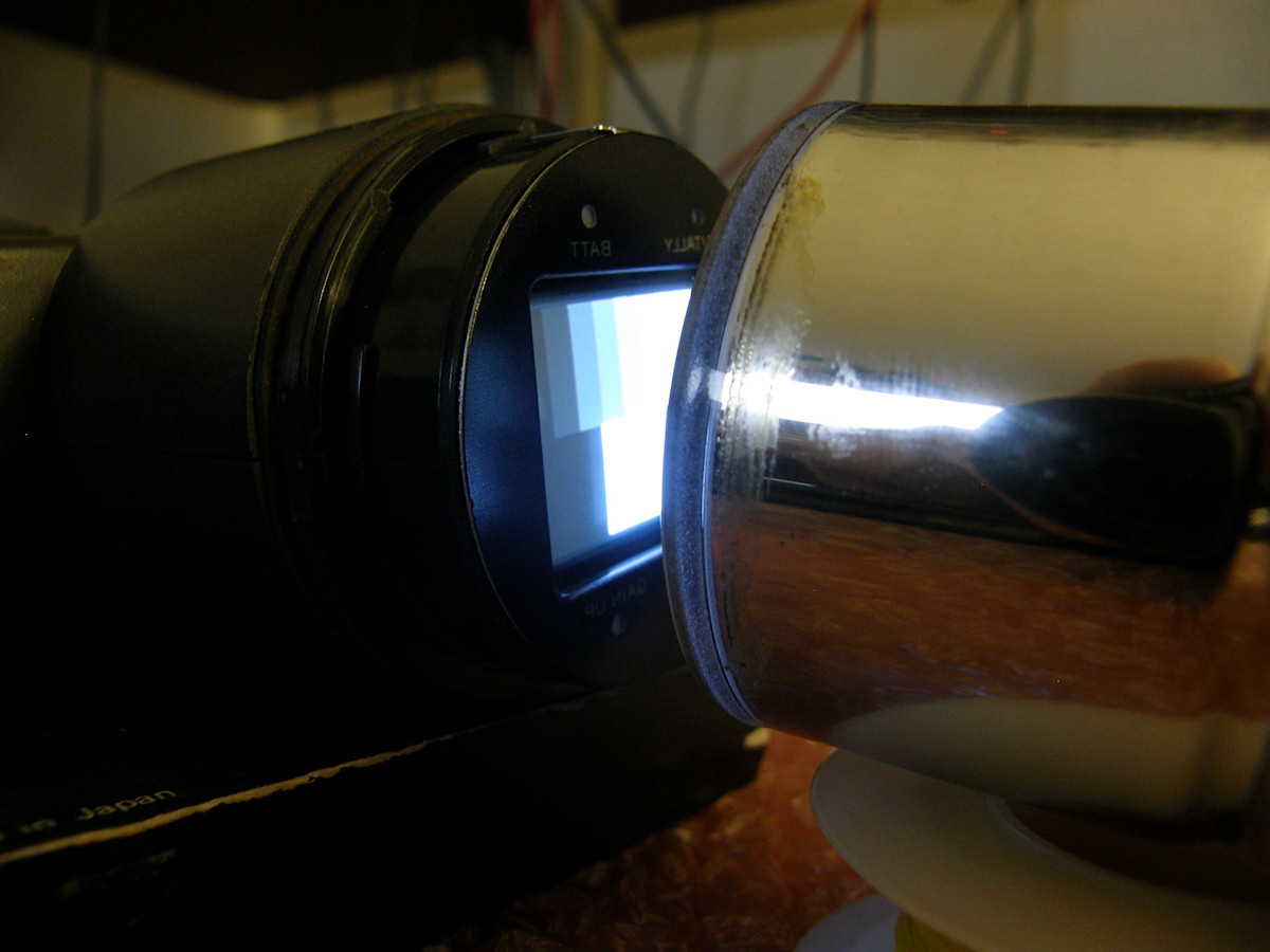
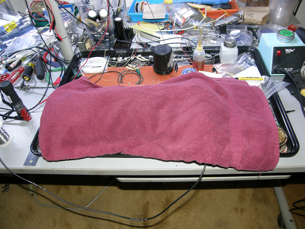
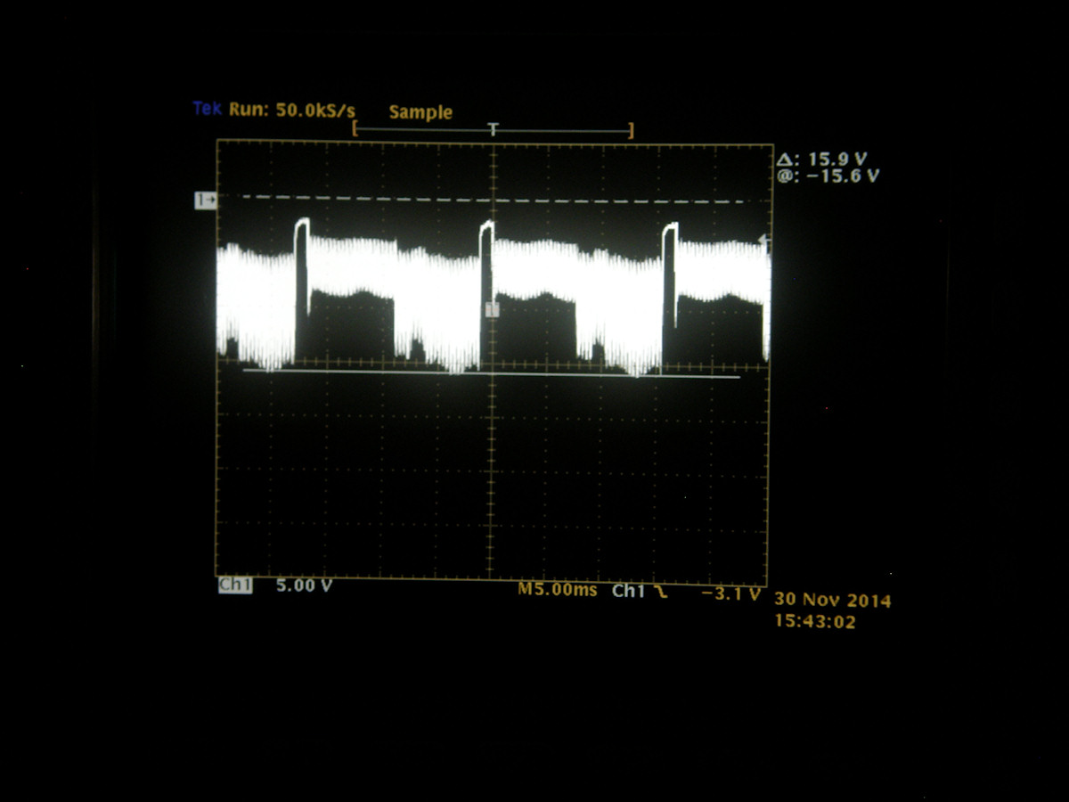
A half step toward flying spot scanning! - 20141130 Got another crazy idea today. Can I see the video directly from the front of a monochrome CRT monitor? So, I grabbed a two inch viewfinder and set out to find out. The quick answer to my question is, "yes". There are other issues but, the principle worked. As you can see in the photos, I placed a camera viewfinder face to face with the EMI 9750T and covered it all up to keep out extraneous light. I used the power supply voltage to control the PMT gain. Recall that at 1,000 volts, the gain was so high, nothing would take the output to zero. It was able to detect microscopic amounts of light. Adjusting the supply voltage until I got a good representation of the on screen video, the operating voltage turned out to be about 250 volts. The CRT makes lots of light! Viewed the output on the o'scope. Because of the persistance of the CRT phosphors, the high frequency info was lost. But, we can see the vertical blanking interval clearly as well as the split between color bars in the upper image and the I/Q flag in the lower half. So, this is the first video-like signal that Labguy has acquired from a photo tube circuit of his own design. Another good day! I know there is a flying spot scanner in my near future. I can feel [Manfred Von Ardenne] smiling down on me. He invented the flying spot scanning method in the 1920s to compensate for the lack of a usable real time TV camera at that time. What a smart guy! Thanks to the fellows in the [Yahoo Groups: OLDVTRs]for their rapid response in providing me with the connector pinouts for the viewfinder. This saved precious time and, no doubt, several vintage viewfinders from an early death! Comments or Questions? [EMAIL] This is an on going project. Check back once in a while to see how it's going. References:
1. [RCA 1P21 Datasheet] [HOME] [ELECTRONICS PROJECTS] Created: November 28, 2014 Last updated: November 30, 2014 |