|
LabGuy's World: PhiloCam - Image Dissector Camera Project, Part 1 [HOME] [ELECTRONICS PROJECTS] [PART 2] [PART 3] [PART 4] UPDATE 20190421: Thank YOU for visiting my project pages. As usual, this project is/was being written in real-ish time-ish. So the early parts 1 and 2 are severely out of date now. Other projects have been completed in the intervening time and have provided me with experience and inspiration for improvements and various other changes to the project. See the bottom of each page for the creation date versus the latest update date to get an idea of the current "freshness" of the information. For the absolutest and mostest recent info, at any time, click through to the last PART n page and it will be the most up to date. Speedy click through links are found at the top and bottom of each page for YOUR convenience. If YOU have the curiosity to see how we got to that stage, read from the beginning. All parts contain useful information, historical insights, electronics tips and techniques, logical dead ends that YOU can now avoid, plus Labguy philosophy and inspirational observations which YOU can take away to use as YOU see fit. Hopefully, YOU will learn things that can apply to YOUR historical research, professional career and or hobby and especially make YOU have warm thoughts about that weird old Labguy many years down the road! "You know, I once read some fascinating stuff written by this really weird guy many years ago...." Have a great day! ~Labguy~ 
The very beginning of the image dissector camera project - 20161030 This project is constructed around an IT&T image dissector tube of unknown type and specs. Normally, this could be a show stopper. However, image dissector tubes are not much more complex than standard photomultiplier tubes. Adding a structured magnetic field region just like in a vidicon, converts the humble PMT into an imager. The construction of this tube is such that it can be operated in a deflection / focus coil that is intended for a one one inch vidicon tube. How convenient, I have boxes of those! This one came out of a Robot Research slow scan TV camera. I obtained this camera tube from Neil, the late propriator of the web site, Almost All Digital Electronics. Neil passed away recently. His site offered a great museum of camera tubes and cathode ray tubes as well as many products aimed at the amateur radio operator and other electronics hobbyists. RIP Neil. Philo T. Farnsworth was an early innovator of television technology. Farnsworth made many significant break throughs in television. The image dissector is Farnsworth's answer to a live television camera. The dissector was, without a doubt, the first working all electronic camera tube. Unfortunately, the dissector tube is an excellent imager for almost all applications except television! The faster the tube is scanned, the less sensitive it is. On top of that, he spent decades fighting RCA in patent disputes. Exhausted and nearly broke, the Farnsworths moved the north east United States and took up residence in the country. Philo moved his entire television lab the their new home. Sadly, the house burned and took every single device and document from all of his years of research and development. After the fire, Farnsworth went to work for the industrial giant International Telephone and Telegraph. IT&T acquired all of Farnsworth's patents as part of his employment deal in the 1960s. Once at IT&T, Farsworth devoted his remaining years to persuing controlled nuclear fusion. He even had some breakthroughs and successes! This is the forgotten part of the life of an incredibly gifted man. In this project, we will be persuing what Farnsworth is most famous for. It's the least I can do to honor a man who directly impacted my career choices more than half a century after his own work. 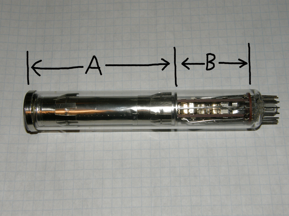
The ultimate evolution of the image dissector camera tube - 20161030 Let's look at the imager tube that I have in a little more detail. This will be the one pass introduction to this tube. In the photo above, note that I have divided the tube into two sections. Section A on the left is the imaging portion of the tube and section B on the right is the electron multiplier section. At the extreme left hand end of the tube is the photocathode. Here is where the lens focuses the image. Chemicals in the PC convert the incoming photons into streams of electrons. These go flying off the back side of the PC. A combination of magnetic and electrostatic fields collomate the electrons. In this way, an electron image of the incoming scene, is projected on the back wall of the drift tube. The photocathode (PC) is operated at between -1KV and -2KV. When a photon strikes the PC, an electron is emmitted on the opposite side, into the imaging section. In the back wall is a tiny aperture which is the entry to the electron multiplier. The action of the scanning coils makes the entire electron image move back and forth over this pin hole. The electrons pass through the aperture and are then amplified by the secondary emmissions of the dynodes. Just like in a regular photomultiplier tube. 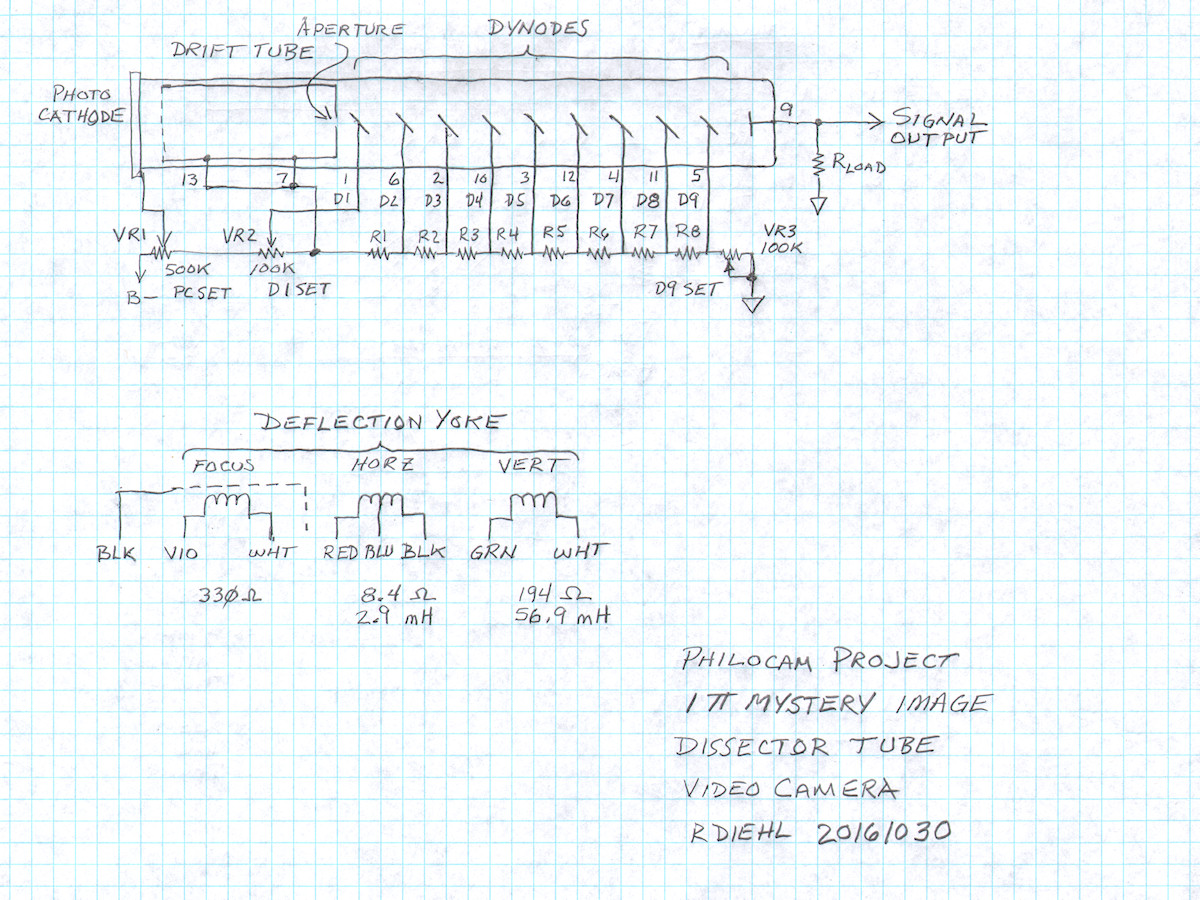
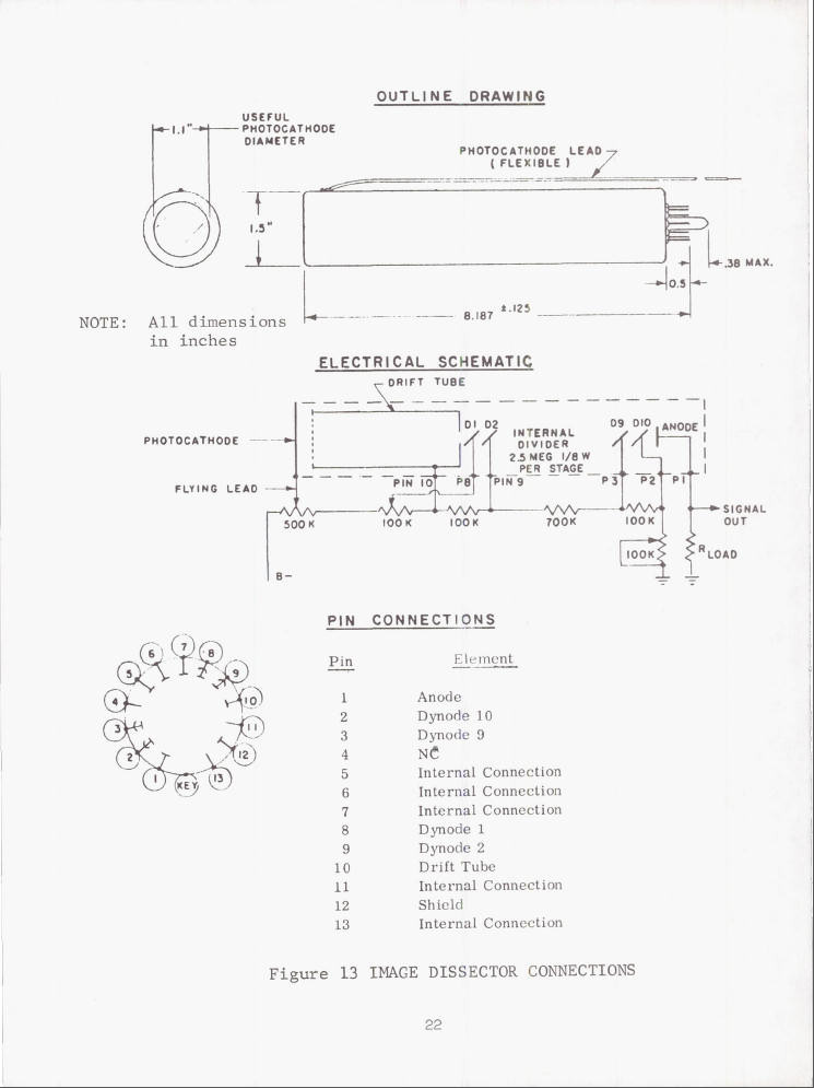
IT&T image dissector pinout and a similar tube's data sheet - 20161030 Fortunately, the tube has no major opaque areas and I was able to trace out the pin connections with relative ease. The data sheet on the right was provided by Neil. It is not exact match for my tube. But, it is close enough for us to set up working bias. It is not uncommon for photomulipliers to operate the dynodes on 100 volt steps. That is my starting assumption. Based on that, I will make a standard long string resistor volage divider and connect the tube's elements to it as shown on the data sheet. I can use a variable high voltage power supply to operate the tube between -1KV and -2KV. If my design is nominal, the tube should operate as a photomultiplier without drives in the focus and deflection coils. I have higher confidence because I tried the same test with one of my [steerable photomultiplier tubes] and it worked very well as a simple light detector without the deflecting coil. That will be the first test I perform with this tube after the high voltage divider circuit is constructed. In the drawing above, R1 through R8 are all 100K ohm, half watt resistors. 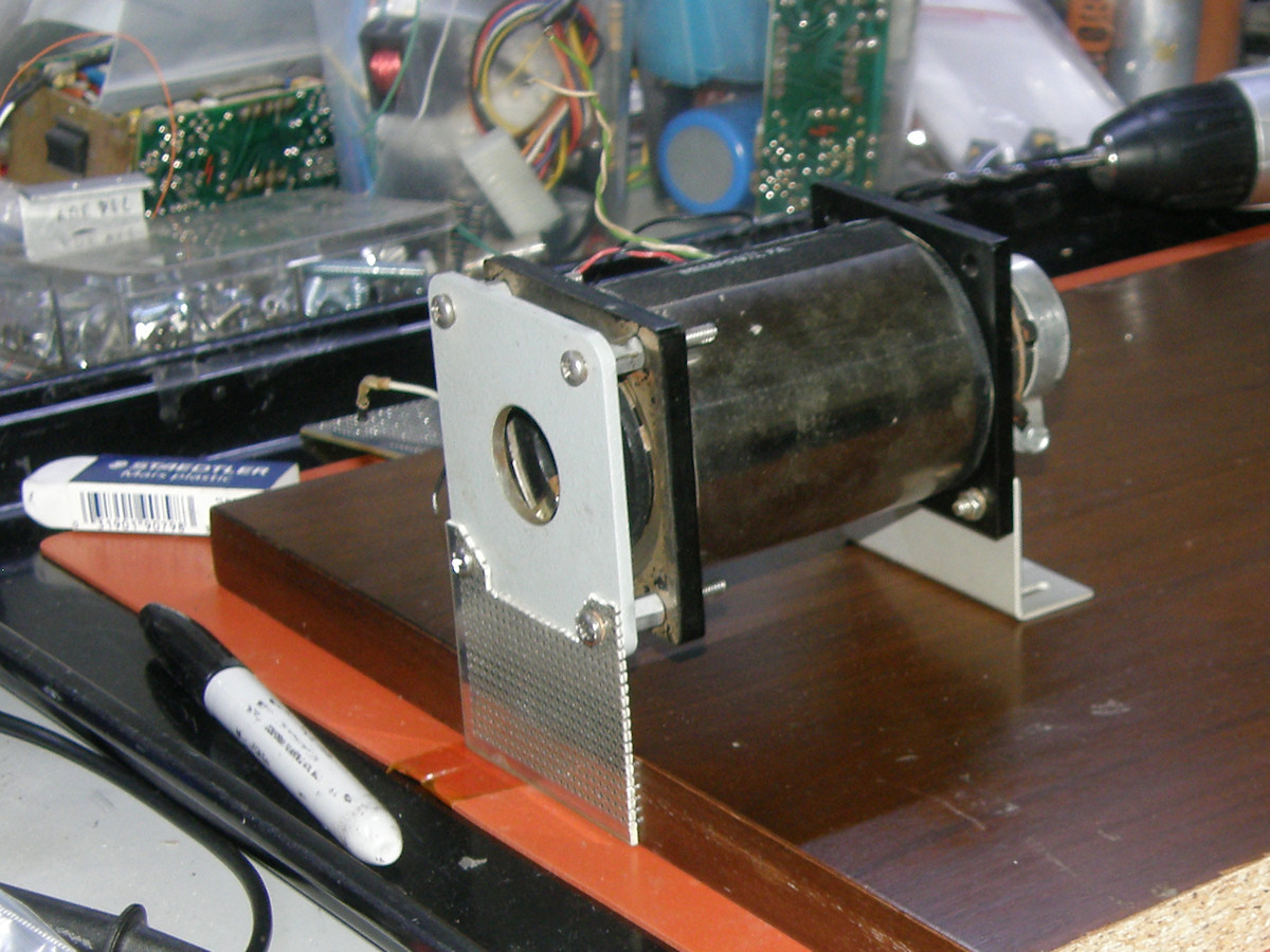

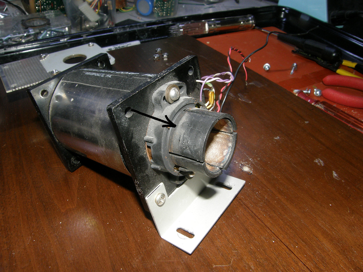

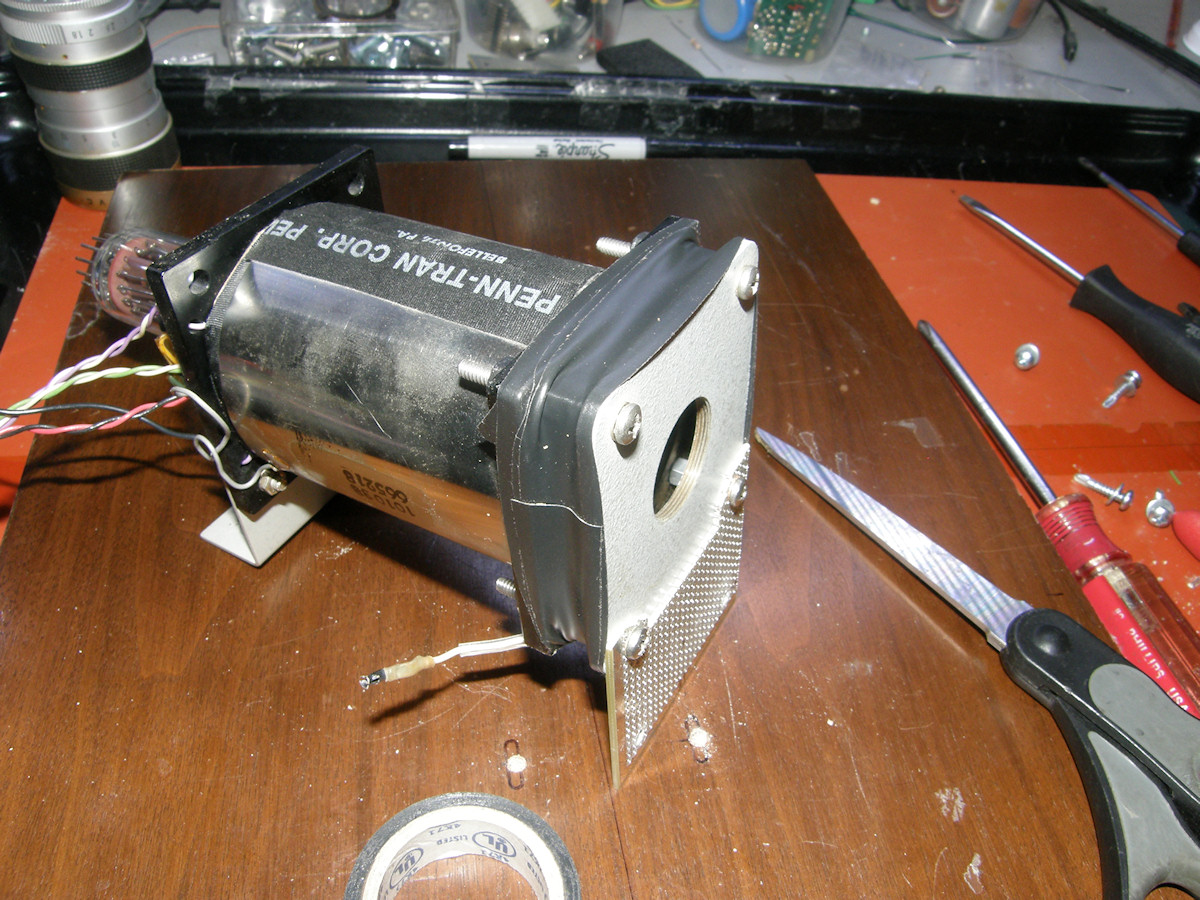
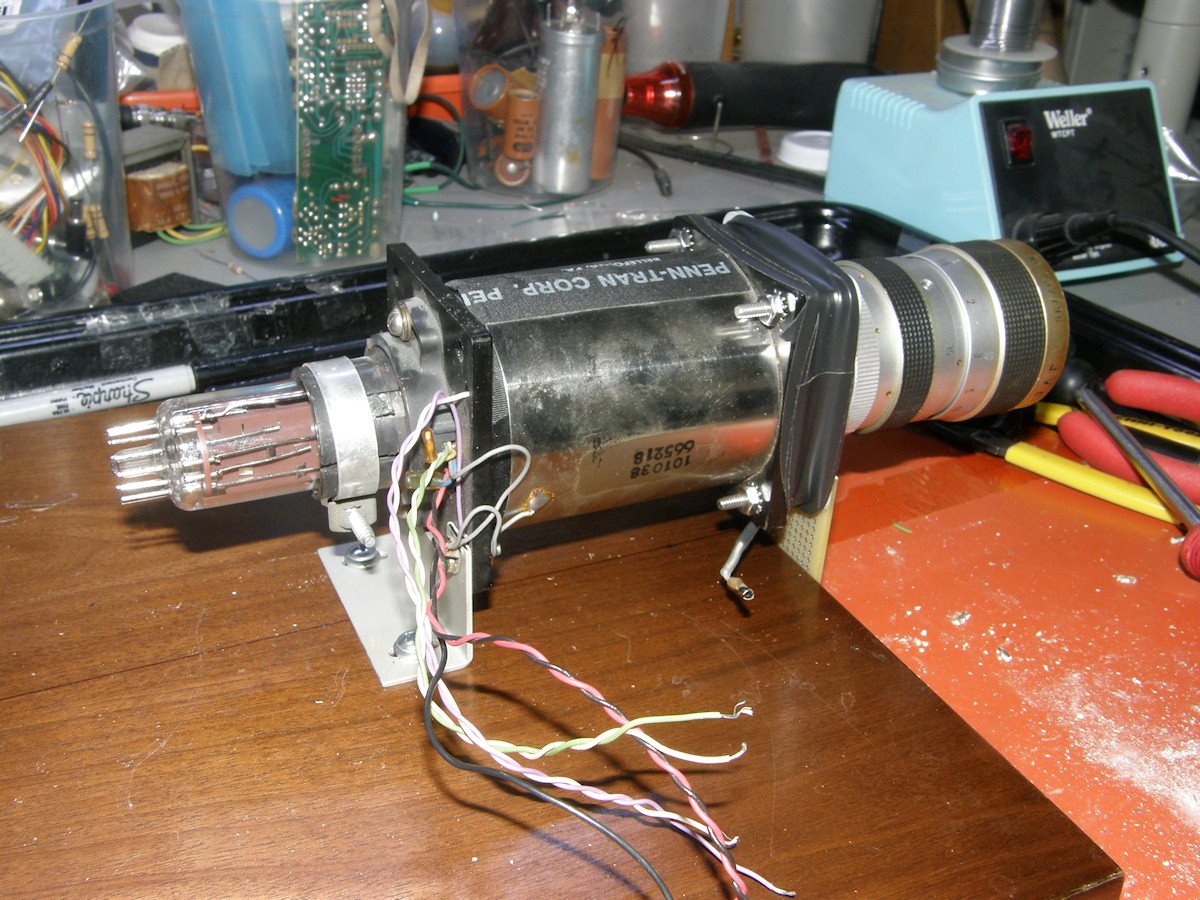
Preparing the deflection yoke for this tube - 20161030 To prepare the used one inch vidicon deflection yoke for mounting the tube and the whole assembly to my breadboard, I started by constructing the main mounts. Next, I removed the alignment magnets, at the back of the yoke, as they are not used with this type of tube. Then I increased the insulation on the PC ring connector at the front of the yoke. For a vidicon this contact operates below 100 volts. Here, we will be operating the face of the tube at up to two thousand volts DC. A couple of layers of heat shrink tubing should do the trick! The tube installed into the yoke in the usual manner and was secured at the back with a compression clamp. Next, I attached the lens mount to the yoke with four short standoffs and screws and wrapped the outer edge in several layers of black electrical tape to block out all light except what gets through the lens. Finally, the entire assembly was secured to the breadboard by four number 6 wood screws. 
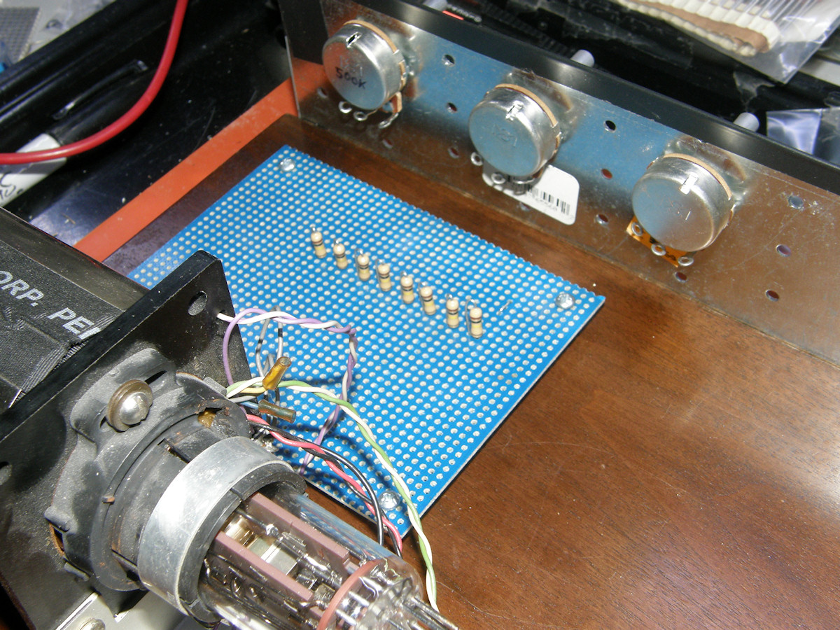
The high voltage board and controls under construction - 20161031 I purchased the potentiometers today and built a simple control panel which I attached to the side of the base board. Next I mounted the high voltage circuit board to the base board. This circuit board is barren of copper or any other metals. That will eliminate arcing or unsafe voltage paths. Its sole job is to support the eight 100K ohm resistors. The wiring diagram shows how simple this circuit truly is. I stood the 100K resistors on end and arranged them so that the wires can be solder direclty to the top lead. With the exception of the bottom end of R8. I made one simple wire loop to solder the jumper lead from VR3. The B- and the PC high voltage leads will not connect to the circuit board at all as I show it in my drawing. There is no need for this. Instead, it will connect directly to VR1. I did the math for the entire voltage divider string and discovered it draws one milliamp of current at 1,500V with VR3 set to its maximum resistance of 100K. Of course this is valid for the actual IT&T F4012 data sheet. We have yet to see if it will adapt for this particular tube. As I mentioned before, I am very confident it will work. Next up, I need to find some female socket pins that will fit the dissector tube pins just right. These will be covered in heat shrink and attach the tube base to the resistor string. No fancy socket necessary. I forgot to look for pins while I was at the surplus store today. Doh! 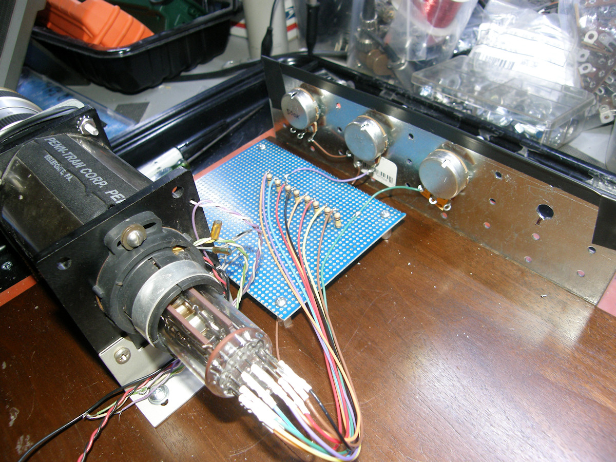
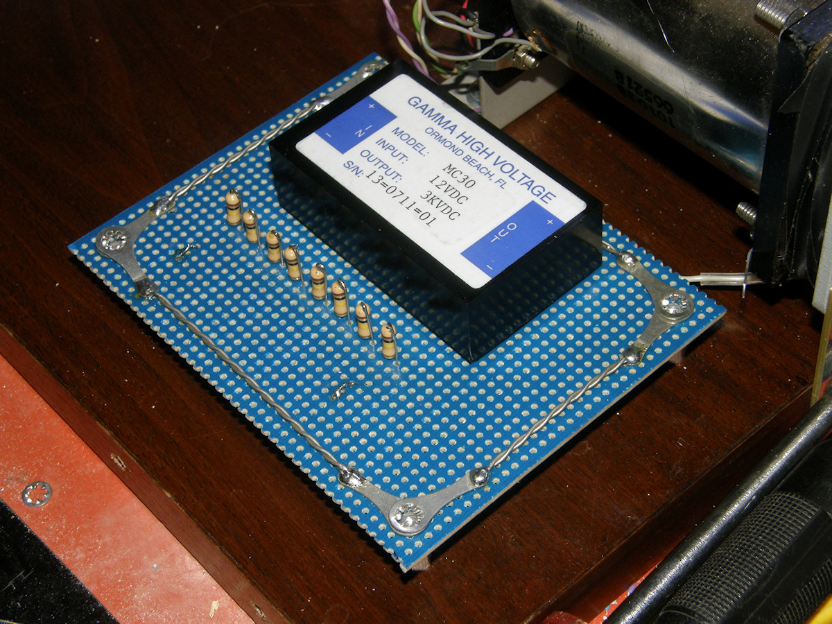
Construction of high voltage board continues - 20161104 I have decided to use a surplus high voltage module I have had wasting space in storage. Same type of power supply as I used in my CRT experiments. Twelve volts in, three thousand volts out at one milliamp of current. This is a 3W power supply made by Gamma Research in the 1990s. The voltage divider string for the image dissector has a total resistance of 1.5 meg ohms. At 1,500 volts, this divider will draw approximately one milliamp. That sounds perfect to me. So, I will be placing a 1.5 meg ohm, 3 watt or greater, resistor in series with the divider string to drop the voltage in half. Will purchase that tomorrow at my favorite surplus store. As you see in the photos, I finished the dissector tube flying leads. These have female pins soldered to the ends of the wires. These slip onto the tube pins perfectly. The pins are covered in heat shrink to mechanically reinforce the joint with the wire and provide some insulation. The other end of the wires cleverly solder to the top loops of the resistors. I have also constructed a ground path around the outside of the board with eye lugs and twisted #22 bus wire. Look closely in the center photos and you can see where I have added two more ground lugs to the deflection yoke. The two ends were not electrically connected, with a resistance of four ohms between them. Not good. wiring all points to a common ground rail will solve that and make all expose metal surfaces rest at ground potential. The last bit will be to add a ground lug to the metal front panel right at VR3, grounding them both with one connection. We don't need any nasty surprises while adjusting the lens or adjusting the pots. 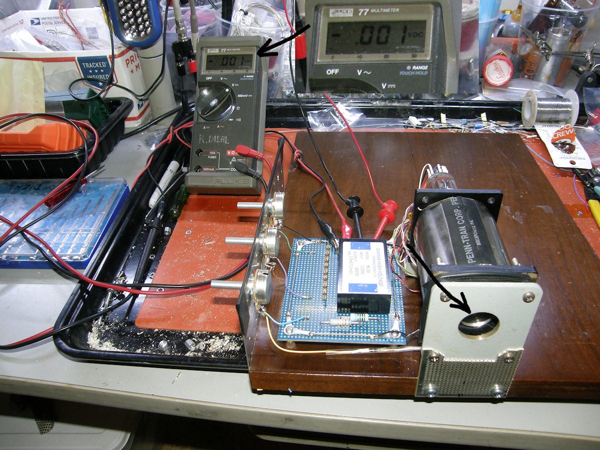
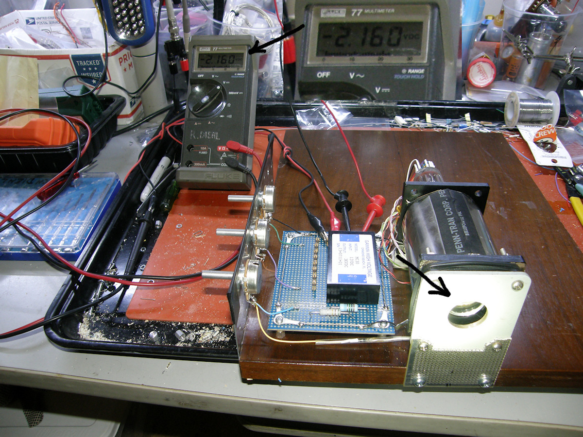
Success! The dissector tube can detect light - 20161105 The high voltage board was completed today and testing has begun. After checking the assembly for faults, I applied first power. No smoke. No arcs. No corona. My insulation measures were working and holding off up to three thousand volts. The divider voltages were all as calculated. So, I removed the lens and used a flashlight to see if I could make the output voltage change. I flashed the light onto the entire photo cathode and observed the output voltage. The results are shown above. 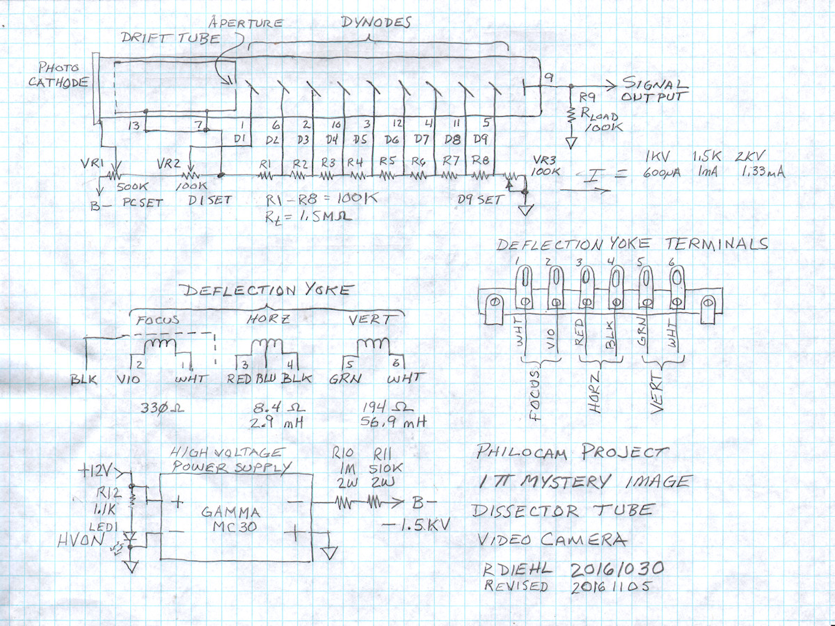
The anode load resistor (R9) is 100K ohms. The anode is the final electrode in the dynode chain. The load resistor drains all those multiplied electrons to form the output signal. The instantaneous current represents the amount of light falling on the photo cathode. In low light, the voltage output is negative 1 millivolt or less. With the high intensity flashlight shining on the photocathode, the output voltage increased to almost negative three volts. The tube is operating in a non imaging mode. The focus coil and deflection coils remain unpowered. Most of the photo electrons are being absorbed by the drift tube walls because they are scattering in all directions due to the lack of a magnetic field to herd them properly. Only a tiny percentage are passing through the aperture, at the back of the drift zone, and into the multiplier stage. So, total efficiency is very low. But, this tests proves that the design will detect light. 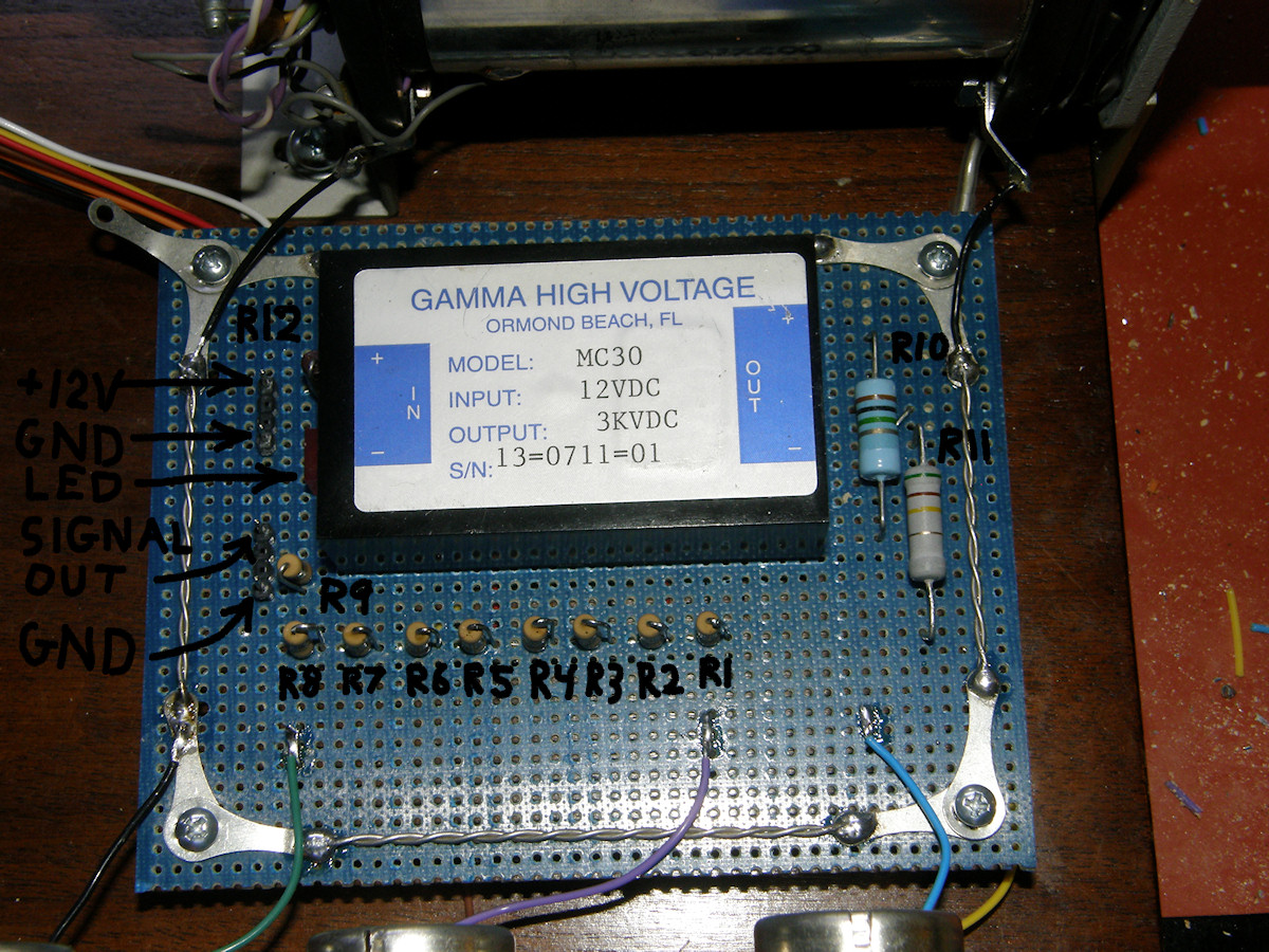
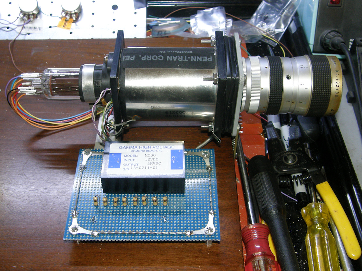
High voltage complete, ready for focus and deflection - 20161105 As you can see, the high voltage circuit lent itself to an elegant layout. The power supply and voltage divider all fit comfortably onto a 4.5" x 3.5" phenolic board with drilled holes on 100 mil spacing. Two of the three control pots are just visible at the bottom of the first image. For safety, I added a power on indicator LED. This board will give the unwary experimentor a viscious bite! Notice the green, violet and blue wires at the bottom edge of the board. I made those solder contacts by taking clipped off resistor leads, bending them into a U shape and wrapping them into a pair of holes. Then I liberally tin them with solder on both sides of the board. They connect into the circuits beneath the board. On top, they serve as simple tie points for the wires. This makes removing the board for service very simple. You can see that all of my ground wires, black, are soldered to the ground lugs in the same manner. The two black leads, at the top of image, connect the ends of the yoke to the board. One more black wire, bottom left, ties the metal control panel to ground. To prevent wear and tear on the deflection yoke leads, I terminated them into a classic terminal strip. This secured the wires away from the high voltage wiring and will prevent unnecessary flexing of them during experimentation. Any test circuits can be connected conveniently to the terminals. Sweet! 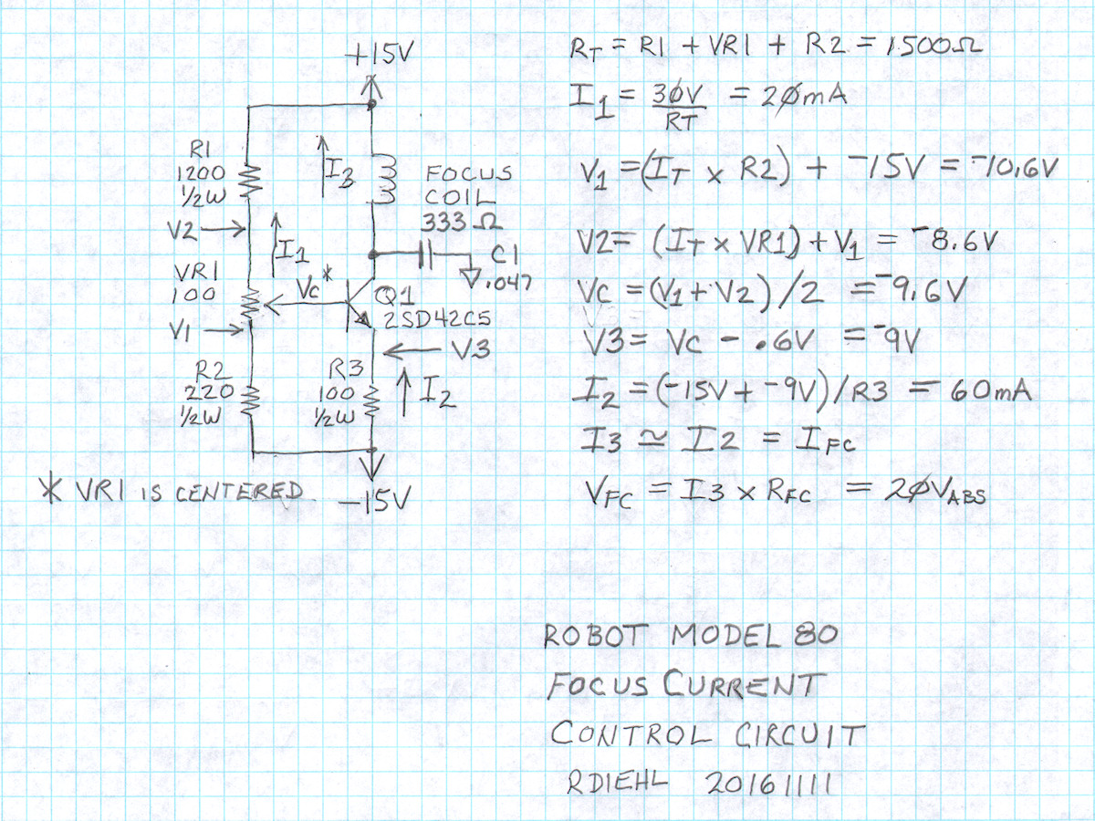
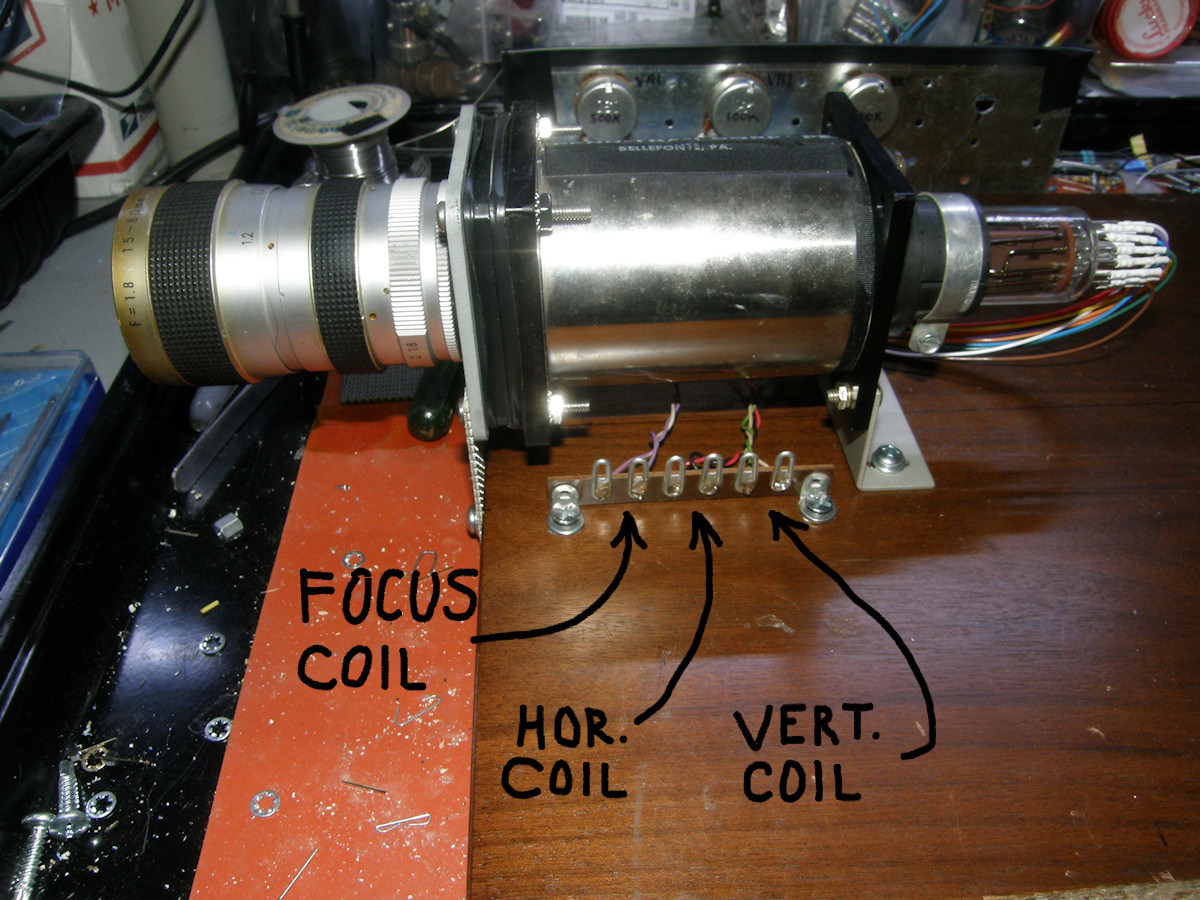
Discovering the focus coil's nominal current - 20161111 Thank you, Kevin Hempson. You are a true pal! I recently requested, in a public discussion forum, service information for the Robot Research model 80 slow scan television camera circa 1975. That camera was the source of this deflection yoke. No, I did not junk the camera. I found the yoke for sale on line at a surplus store. Knowing the yoke's source, we can use the service manual to find out how much current the focus coil requires. Kevin came through for us. This deflection yoke is designed for common one inch vidicon tubes. The image dissector is designed to use a common vidicon deflection yoke (we presume). This brings up several interesting questions. How strong should the magnetic field be and how much current does that require? A magnetic field is created when a steady DC current flows through the focus coil and runs parallel to the central axis of the tube. It makes the photo electrons, emmitted by the photo cathode, travel in straight lines to back of the drift tube. This is called collomation. The electrons are all moving parallel in perfect columns. An electron equivelant of the visible light image is projected on the back wall of the drift tube. In the center of the back wall is an aperture. It is the entry point to the dynode multipliers. The deflection coils move the entire collomated image back and forth and up and down, over the aperture to dissect the image. More on that when we get to deflection. The focus coil is wound like a solenoid around the outside of the deflecion coils and encompasses the region of the photo cathode and drift tube. Which way should the magnetic field point? Does it even matter? I guess we'll find out experimentally. The following exercise will provide a starting point and allow the PhiloCam project to move forward. Let's return to discovering the nominal current for the focus coil. Looking at the original current control circuit (you can't call this a regulator), we are able to calculate the voltages and currents with ease. Starting in the voltage divider on the left side, we calculate the total resistance, RT. Just ignore the loading of the divider by the base lead of the transistor, Q1, for now. Next, divide RT by 30 volts and get I1 which is 20mA. With that information, we can calculate the voltages at each end of the variable resistor. Those same voltages will appear at the top of R3, minus the point six volt base emmitter juntion drop of Q1, when VR1 is turned through its full range. For the nominal calculation, presume VR1 is centered. The voltage on the wiper is called VC in my drawing and it is minus eight point four volts. (The -9.6V shown for VC on my schematic is incorrect) This makes the top of R3 equal to minus nine volts, and the voltage drop across R3 equal to six volts. Six volts divided by one hundred ohms equals sixty milliamps. Q1 collector current is equal to Q1 emmitter current plus Q1 base current. For the 2SD42C5 transistor, the minimum hFE is given as 40 in the datasheet. That makes the base current two and a half percent of the emmitter current. For this rough approximation, we will ignore base current. That makes the focus coil current equal to roughly sixty milliamps with VR1 centered. C1, a .047uF capacitor, is used to bypass AC noise to ground and prevent the transistor from oscillating. Because the focus coil resistance is three hundred thirty three ohms, a minimum of twenty volts is required for 60 mA of current to flow through it. (Don't you love all the round numbers falling out of these calculations? Did the orignal designer get these answers on his slide rule? It's quite possible!) The circuit example shows a bipolar 15 volt power supply used to develop an operating range of thirty volts. Perfect! I'll do that. All totally awesome electronics projects eventually deteriorate into power supply projects! ~Labguy~ 
Labguy's preliminary focus current regulator circuit - 20161112 Another simple circuit to do a simple job. This is an adaptation of the voltage to current converter I used for driving the RGB LEDs on my mechanical television. The right side of the circuit is nearly identical to the original circuit from the Robot Research model 80 SSTV camera. Using an opamp with feedback, this circuit will keep the top of R3 at exactly the same voltage as the center wiper on VR1. As long as that voltage and the -15V power rail does not change, the current through R3 will remain constant too. Notice I increased the resistor values in the control voltage divider divider by 50X. This drops the power consumption dramatically, preventing the resistor string from heating up and drifting in value. The opamp power connections may seem odd at first glance. I have the positive supply pin tied to ground. This means that the opamp will only have to dissipate half the power it would if it were connected across 30 volts. All of the control voltages are occuring well below zero volts, so the output of the opamp never needs to swing positive. Also note that the 20 volt drop acrosse the coil means the top of the transistor is 5 volts below ground at nominal current. Nothing in the circuit is operating in the positive domain. Clever, huh?. 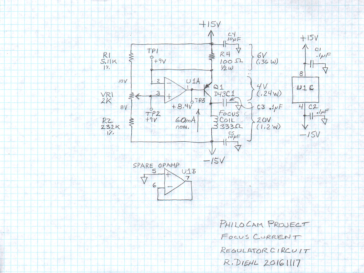
Labguy's final focus current regulator circuit - 20161117 I could not find the exact D42C5 NPN transistor as shown in the original camera schematic. I did, however, locate the PNP complement of it, the D43C1. You will see that the schematic is now physically inverted from before. I have decided to not tempt fate and wired the opamp directly to +/-15 volts. It can tolerate up to +/- 18 volts. U1 will be an MC1458, 8 pin DIP, in a socket. I can try other opamps if the need arises. This circuit operates exactly as previously described. Just the mathematical signs were changed. C1 and C2 are placed right at the power pins of the opamp and take the shortest path possible to ground. These will send any noise signals, over a few hundred Hertz, to ground. This gives the opamp very clean power. C3 is connected as close to the collector of Q1 and also takes the shortest route possible to gound. Its funtion is to stabilized the transistor. It is operating in a very high gain region of its curve and is likely to oscillate. If that oscillation got into the focus coil, it would apper in the output signal. The circuit board and capacitors that I use are nearly ideal for this purpose as will be shown in the following segment where I construct the circuit for practical use. Notice how I have drawn the opamp on the schematic as three separate segments. Two opamps and the power pins. This makes for a very clean, easy to read circuit diagram. Assembling the circuit from this drawing is easier because the non related functions are separted. Opamp U1B is wired with its output tied back to the negative input and the positive input is grounded. Gain is reduced from "huge" to 1 and the input is tied to zero volts. This reduces unnecessary noise in your circuits. An opamp that has its pins left floating will amplify every bit of signal noise and drive the output into rail to railsaturation. So, what? You may ask. Thirty volts of white noise is a lot of signal being generated on the same die with opamp U1A, which we are trying to keep as quite as possible. Any noise we send to the focus coil ultimately ends up in the video! 
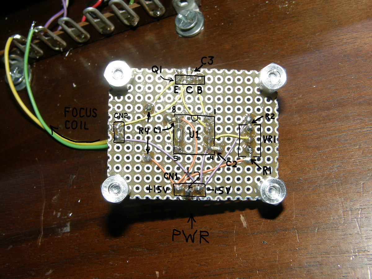
The final product is revealed. Let the collomation begin! - 20161119 Success! Construction completed. Testing completed. 6 volts dropping across the 100 ohm resistor and 20 volts across the focus coil at first light! The pot was apparently pre-centered. It works perfectly. Nothing gets very warm. No oscillations. We have an experimentally nominal collamation field in the image dissector tube now. That was almost anti-climactic. Now its off to figure out a strategy for scanning in some manner. R4 is the big resistor on top of the board. If you squint closely, you will see R1 and R3 soldered to the outer pins of the pot, VR1, bottom view. Orange wires are +15 volts and Violet are -15 volts. Yellow is general wiring. Again, squinting closely, can you find the 0603 SMT 0.1uF capacitors? One is at the center pin of the power transistor, Q1. The other two are located on the corners of the opamp. I have yet to install the two ceramic 10uf, SMT 1206 size capacitors C4 and C5, on the +/-15 volt pins of the power connector. (Can't find them at the moment!) Lastly, the focus coil connections are able to be switched, on their two pin header, easily in case the polarity matters. Who says you can't bread board with surface mount? I thinks its more efficient than leaded parts. It certainly is much cleaner. The power supply becomes a problem again - 20161120 I have run out of convenient power supplies for this project. More will be needed before it is completed. So, I purchased a 32VCT transformer and a pre-made bipolar power supply rectifier and regulator kit on Ebay. Those will be here, from China, in about ten days. I am really tired of building power supplies! There will be another board for the additional voltage regulators that will inevitably be needed. Currently, we need +/-15V for the focus regulator and +12 volts for the three thousand volt power supply. The bipolar fifteen volts will be provided by the regulator kit I purchased. A +12 volt regulator will be operated from the +15V line for the high voltage supply and so on. I am going to revisit the power opamps I tried for deflection coil drivers in a previous project. Those also conveniently operate from +/-15 volts. Another rising issue is the way I have constructed the camera breadboard in the open air. There is quite a bit of noise on the output pin of the dissector tube. This is coming from the 3KV power brick. I will be adding some 3KV rated disk ceramic capacitors at key points in the voltage divider to lower the noise on the more sensitive pins of the tube. This will not be totally effective because of the length of the wires going to the back end of the tube. They are long enough to make very effective radio antennae. All the electrodes on this tube operate at near infinite impedance and are highly sensitive to interferrence and noise. The high gain of the multipliers magnifies the problem. There is a high probability that the tube and yoke assembly will need to be put into a shielded metal enclosure. The HV power supply board may need a separate box of its own as well. We're having fun now, aren't we? While we are waiting for the power supply parts... - 20161124 Allow me to think out loud about deflection strategy. We could drive the yoke from a vidicon camera deflection board at 525/30 scan rate. At that speed, the dissector is as sensitive as a vidicon - the signal amplitude is miniscule. We could drive the yoke with the function generators, as I demonstrated in a recent project about the [5FP family of CRTs]. In that case, the function generator must drive two loads. The dissector deflection yoke and one of my XYZ scopes. Each will require a different drive level for a properly proportioned picture. The slower you scan a dissector tube, the more sensitive it becomes. Using the function generators, we scan at any slow rate we choose. We could scan a 100 line picture at 10 frames per second and the dissector would be at extremely high sensitivity. This makes it much easier to get an easily usable output level from the tube. 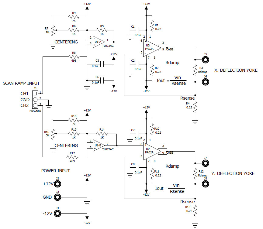
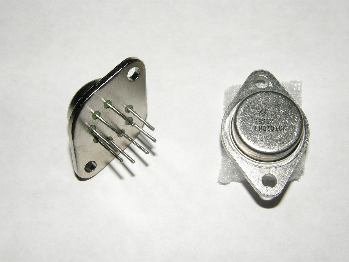
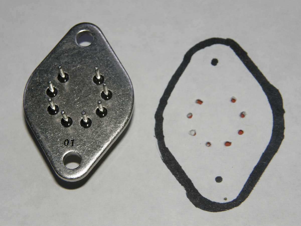
This could ressurect my [magnetic deflection amplifier project] that "died on the vine" two years ago. Its final form is shown in the schematic above. (Disregard the PA02A opamp in the schematic. The cad program had that one in the library, but not the LH0101 we see in the photos. The pinout and footprint are identical beetween them.) In review, I would go back and add a pair of input level controls. I have also obtained more of the opamps and even located the heat sinks with the 8 pin hole pattern that fits the LH0101. I even laid out a circuit board, which I am now seriously considering to have made. The current testing is to connect the tube deflection coils to my function generators and drive them directly. This worked quite well for the 5FP CRTs. I have managed to get enough temporary power supplies to fire everything up at the same time. While doing this test, we can observe the multiplier anode output on the o'scope to see if it resembles a regular video signal. Does it move with hand waving in front of the lens? Does it change amlpitude with the presence and absence of light? Does the waveform contain image like high frequencies? At this time, this test is being overwhelmed by external noise pickup from the high voltage power supply. So, there is another issue I could address. Since I am off work for the next four days, I may construct breadboards of the scan amplifiers. I think I have all the parts on hand. That will be some heavy construction. I also purchased two aluminum project boxes. The first was far too short to hold the yoke and tube. The second is barely long enough and the slip on pin connections will be mashed against the back wall of the box. So, I am not sure how to procede there. Will search my junk pile for a few other project boxes I have stashed in various locations. Stay tuned! This is an on going project. Don't forget to bookmark and check back occasionally for updates. REFERENCES: 1. PDF file [ITT F4012 Image Dissector Tube ] from around the late 1960s? 2. PDF file [LM1458] dual operational amplifier in 8 pin DIP package 3. PDF file [D43C1] PNP power transistor in TO202 package 4. PDF file [LH0101] 60W high power opamp 5. Basic64 / Text file [SYNC_ROM.bas] Source code for creating the Sync Generator flash PROM 6. Basic64 / Text file [IMGx8_ROM.bas] Source code for copying eight 256x256x8 image data files to the flash PROM [HOME] [ELECTRONICS PROJECTS] [PART 2] [PART 3] [PART 4] |