|
LabGuy's World: PhiloCam - Image Dissector Camera Project, Part 3 [HOME] [ELECTRONICS PROJECTS] [PART 1] [PART 2] [PART 4] 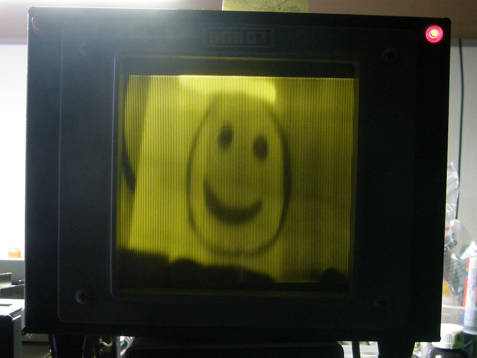
The (potentially) NEW PhiloCam video format! - 20190420 It is time to rethink how to proceed with this PhiloCam project. I have just completed my [TV monoscope project, The Chief], and gained a great deal of experience with scanning circuits. (Thanks to my good friend, Howard Katz! Thank you for your patience and endurance.) There was also the resurrection of my Robot Research classic slow scan television equipment which provided me with greater additional inspiration. (The image in the photo is originating from the Robot Research model 80 vidicon camera and being displayed on the model 61 "viewfinder" monitor.) Not wanting to be conventional, I have decided to build the camera in a manner similar to what Philo T. Farnsworth may have witnessed* in his lab in the 1930s. Heavy emphasis on the MAY HAVE. So, I have settled on a 15 frame per second 267 line video system format. This will result in a theoretical bandwidth of 1.07 MHz. (Roughly 267x267x15) It is derived from the Robot Research model 80 television camera, which operates internally at this rate. An accessory "fast scan" video monitor, model 61, also operates at this rate. * I will initially attempt to use that monitor with the PhiloCam in an attempt to avoid immediately building a video monitor. Though I will if necessary, and can also modify the scan rate then if I choose to. I think that Farnsworth actually had about a 100 to 120 line picture running at 20 to 24 frames per second. But, this is not certain at this time. My new approach can easily be adapted to a large range of scan systems. Read on! Currently, the Robot monitor runs AT 4,000 line per second, scanned in the vertical direction, and 15 frames per second scanned horizontally. As seen in the photo above. The PhiloCam format will operate in the more normal television style, with the scanning lines oriented horizontally. The Robot model 61 monitor will be modified by rotating the deflection yoke the same amount to the right and by reversing the connections to the horizontal coils. PhiloCam and Robot format use a square picture format with an aspect ratio of 1:1. (The photo above looks better as a still image than when your eyes being assaulted by the 15 frame per second rate!) 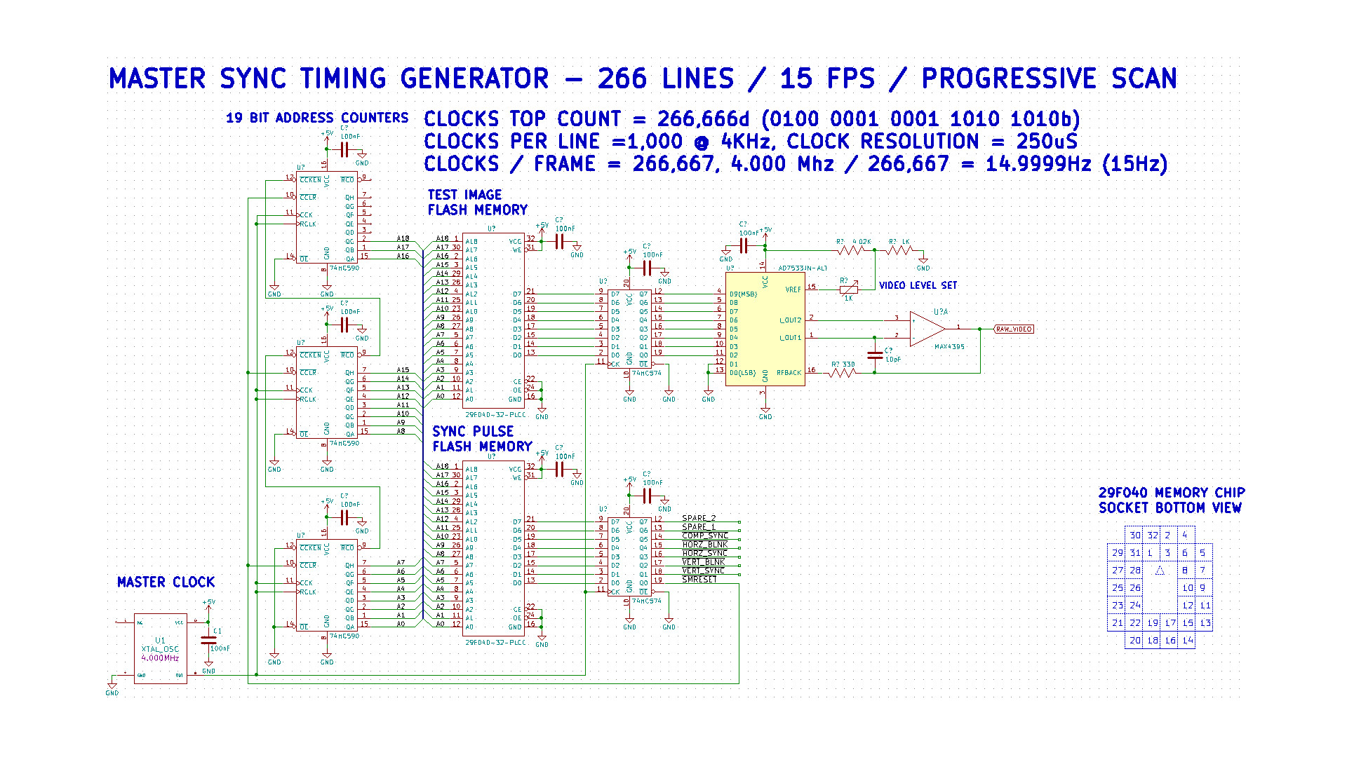
The (outdated) NEW PhiloCam video format sync and test signal generator circuit! - 20190421 At this point, I have begun designing the necessary synchronizing generator. It is based on technology and methods I last utilized professionally in the early 1990s. The PhiloCam format currently scans at a rate of 4,000 lines per second at 15 frames per second progressively scanned, not interlaced. This results in a total of 267 lines per frame, of which 256 lines are active video and 11 lines are vertical blanking. This is roughly double the number of scan lines Farnsworth viewed in his earliest experiments. But, will suit our purposes just as well. The sync generator starts with a 4.000MHz crystal oscillator with a clock resolution of two hundred fifty microseconds (250uS). This drives a string of three 74HC590 8-bit synchronous counters with internal storage registers. These are driven as a 19 bit counter with a top count of 266,999 (267,000 clocks = 267 scan lines). The storage registers guarantee that all 19 outputs change simultaneously. The address is applied to a 524,288 byte, half a megabyte, flash memory chip (Silicon Technology M29F040). This memory chip will contain all of the complete synchronizing pulse trains. Think of the timing pattern ROM as the perforated paper roll in a player piano or the little drum with pins in a music box. It runs in a perpetually repeating loop. Easy peasey! A second half megabyte flash memory chip and 16 bit address counter will contain eight video test images. By using flash memories, we can change the timing patterns or test images at will. The chips are easily erased and (re-)programmed with simple Basic programs and a low cost USB interfaced device programmer. Individual images are selected by a ten position binary coded decimal rotary switch. Positions 0 to 7 select memory images, position 8 is dissector video positive and position 9 selects dissector video negative. This circuitry is all contained on a single 4.5 x 3 inch prototyping circuit board. When operating, this board can produce complete video images, from the memory, to verify all is working correctly and that the Robot monitor drive is working properly before we even attempt to get the video from the image dissector tube portion of the project. Camera tube scanning is produced by a separate deflection yoke driver board. To my delight, someone has recreated a modern clone of Microsoft's original Quick Basic! Its called [QB64] and its FREE from QB64.org. This (Microsoft QB4.5) is/was one of the best Basics ever written! It will provide me with the ability to synthesize the bit trains, as true binary files, for the sync PROM and also to convert and embed the image files into the image PROM with relative ease. The raw binary video files will be prepared in advance using my favorite image processing program, Corel Paint Shop Pro. 
Final version of the schematic of the sync generator and frame buffer - As of 20190522 You can click on the diagram for the full size view. You will note that the sync generator portion, across the top of the diagram, is mostly identical to the original description. The lower half of the circuit, comprising the frame address counters and the video image memory are new. The digital to analog converter circuit is also fully evolved and developed at this point. In the lower left is the images selector input. This applies a three bit binary number to the upper three bits of the image memory chip. Since each image consume exactly 65,536 or 256x256 bytes, this works out perfectly to eight images with a three bit selector code. The binary adder floating near the selector input is for applying a future offset value to allow switch positions zero and one to select the dissector tube positive video and negative video respectively. I also then added two scan ramp generators into the design so that the images could be easily viewed on any o'scope before the Robot research 61 monitor was actually interfaced to the new board. These ramp generators can be, will be and were reused later during the debugging of the actual camera tube circuits as well. 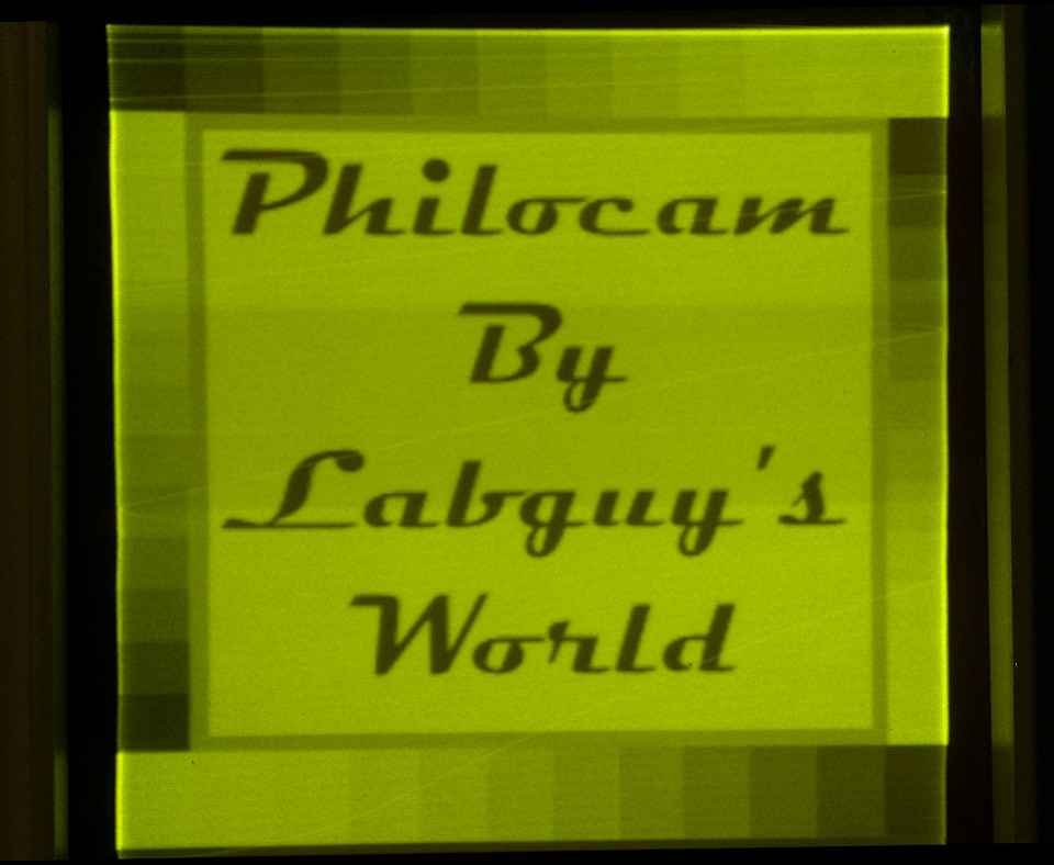
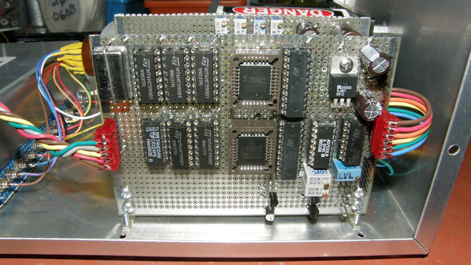
The NEW PhiloCam video format sync generator and frame buffer completed! - As of 20190502 (20190521) By the beginning of May, I had completed the sync generator and frame memory. Full restoration and conversion of the Robot Research model 61 monitor was completed just before that. You can clearly see the remarkable results in the photo above. There were the usual issues with spinning the design to incorporate various short comings of the originating presumptions and collisions with reality along the way. Translation; Everything I knew and stated before was wrong! In the end, success was achieved through shear persistence. To summarize, the steps outlined above were followed and many improvements were discovered, incorporated, and added along the way. Referring to the previous schematic diagram, the image memory could not be operated from the same address counter as the sync pattern memory. Using that method would have resulted in a science fiction remapping of the image data and would only allow two images to be stored in a memory chip that could actually contain eight complete images. Not acceptable! 
The initial 8 photos for the frame buffer memory - All images (C)2019 Labguy's World Two Quick Basic 64 programs were required to produce the binary files for the memory chips. These were transferred to the chips using a low cost device programmer purchased from Ebay. (TL-866). The source code for the sync generator is shown below in the Reference section. The sync patterns are explained in the YouTube videos to follow. All but one of the images above made it into the final memory chip. Due to DAC issues with an earlier wiring error, the poor chicken was removed and replaced with a dollar sign. Each picture, in raw binary format, is 256x256 8 bit pixels. That's 65,536 bytes per image and they fit perfectly into the 524,288 byte flash memory chip. The purpose of the built in photos was to be absolutely certain that the converted Robot Research monitor was operating perfectly before we try to display images from the camera tube itself. There is nothing harder to debug than a complex system where two or more elements of the system are malfunctioning or operating in some strange way. So, the entire sync generator and frame memory, along with the video monitor were fully debugged before moving on to developing the camera scanning and tube support stages. 
The final results as viewed on the converted monitor - All images (C)2019 Labguy's World Here is the final result of the monitor conversion and sync generator part of the project. That's a lot of success in one place! Photo 1 is the Philocam logo screen. Photo 2 is of the man himself. Photo 3 is the good old Indian head test pattern. Photo 4 is the first photo that I ever saved to disk way back in 1986. Photo 5 is your author looking very surprised at the results of the work so far. Photo 6 is a tribute to a apocryphal moment in the history of television, where the investors asked when they would see some dollar signs coming from there investment. Photo 7 is the radiation trefoil for its roundness and flat brightness fields. Photo 8 is a picture of the Indian chief lithophane from my test pattern generator project, The Chief. The geometric distortion you see here is the result of off axis photography and not a fault of the video monitor. It's pictures are very square indeed! Now, back to the circuit descriptions. 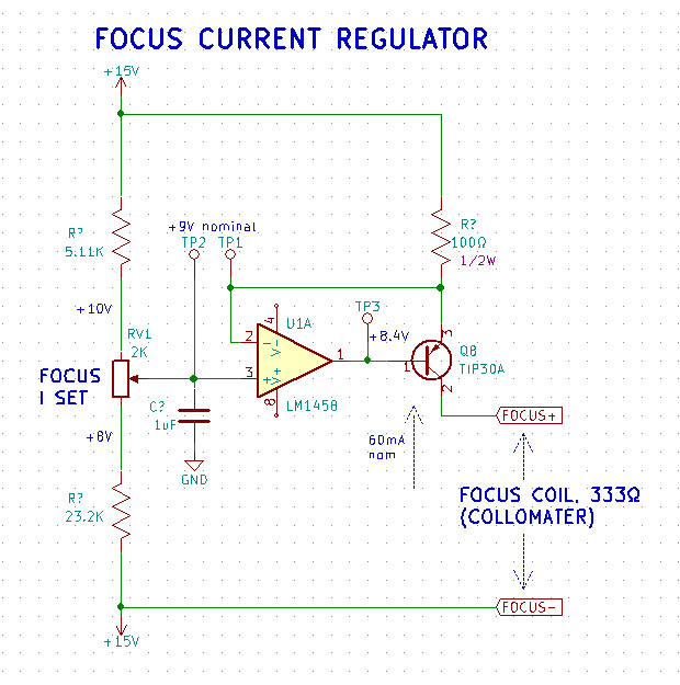
Final version of the schematic of the focus coil current regulator - As of 20190522 The focus coil current regulator is shown above. It is a very simple constant current source designed to provide a constant 60mA to the collimating coil, commonly misnamed the focus coil. At 333Ω, the coil will have a drop of about 20 volts at 60mA. This is the only reason I had to design this system to run plus and minus 15 volts DC, though my preference was for plus and minus 12 volts DC. With only 24 volts, the system did not have a comfortable margin for maintaining the 20 volt drop across the coil. 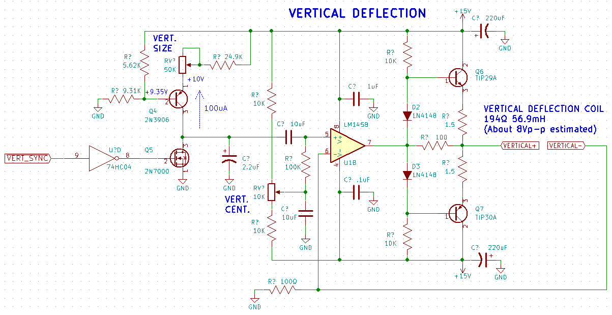
Final version of the schematic of the vertical deflection circuit - As of 20190522 The vertical scan ciruit is rather conventional. Estimating that I need to supply the scan coil with between 6Vp-p and 8Vp-p, I designed a system that can dial down to only 4Vp-p and up to 30Vp-p! That should do it. The scan ramp starts with the discharge switch transistor Q5, which zeros the voltage on the 2.2uF capacitor during the vertical sync interval. After the vertical sync pulse is over, the capacitor charges at a constant rate determined by the the constant current source formed by Q4. The 50K pot sets the current to give the desired scan size on the face of the vidissector tube. A DC offset voltage is added to the AC coupled ramp signal to allow for scan centering in the tube. The ramp is amplified by the opamp and the two power transistors in the output stage. Feedback returning from the deflection coils goes to the 100Ω resistor that is tied to the feedback pin of the opamp. Because of the induced delay through the yoke coil, the output momentarily spikes to the maximum negative potential of -15V, providing a flyback pulse for retrace. 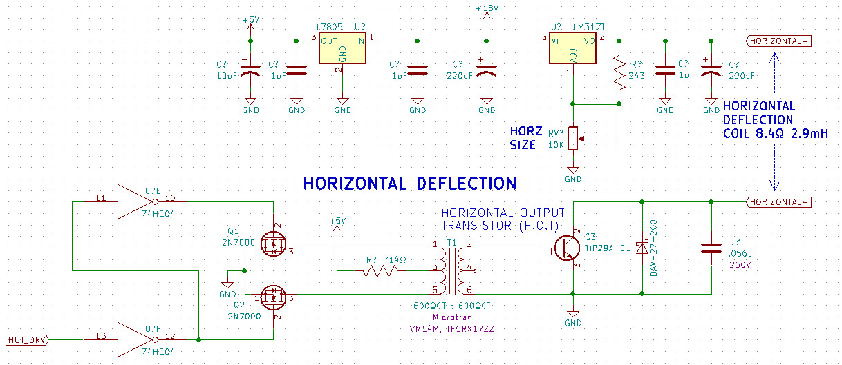
Final version of the schematic of the horizontal deflection circuit - As of 20190522 The upper half of the schematic represent the two voltage regulators. One is a fixed +5 volts for the 74HC04 inverter chip, the other is an LM317T adjustable regulator going from +1.2 volts up to almost +13 volts and allows for adjusting horizontal scan size. The horizontal output transistor (HOT) drive is generated in the flash memory on the sync generator board. It is a 50% duty cycle square wave that drives the base of the HOT. The square wave is split into two opposite phases to drive the two switching FETS that, in turn, drive the coupling transformer. Current to the transformer, and consequently, the base of the HOT is limited to a safe level by the 714Ω resistor tied to +5V. When the transistor is first switch on, current flows from the adjustable regulator (positive current flow analysis), through the horizontal deflection coil and through the HOT to ground. The magnetic field, in the coil, begins to build and deflects the electrons to one side of the tube. As soon as the HOT drive goes low, the HOT goes open and the coil's magnetic field collapses, creating a large negative voltage spike. This spike is absorbed by the diode, which essentially shorts out the coil, speeding up the collapse of the field, driving the scan to the opposite side of the tube. Now current begins to flow back through the capacitor in the opposite direction, driving the electrons back toward the middle of the tube. If all is tuned correctly by the 0.056uF capacitor, the beam reaches the middle just as the HOT drive switches on again and the cycle repeats. The capacitor value is selected by observing the scan current on the o'scope and selecting values on the capacitor substitution box for the best result. 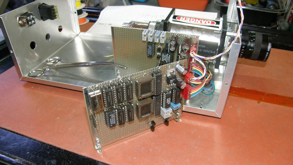
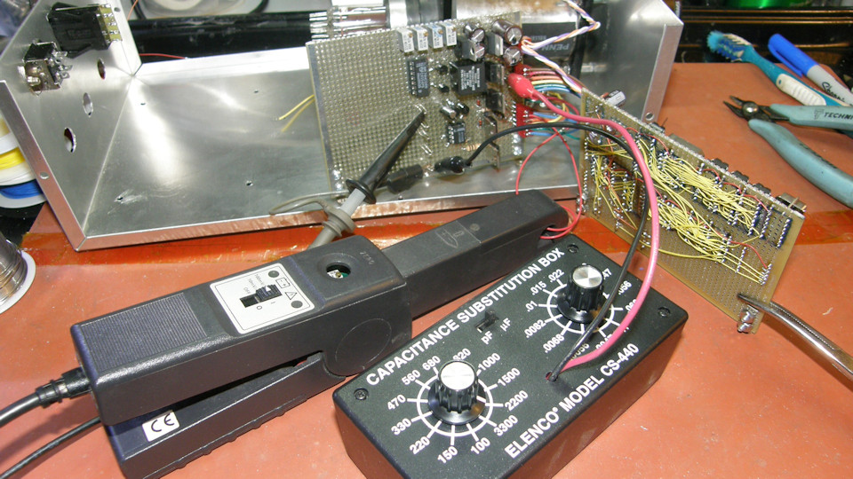
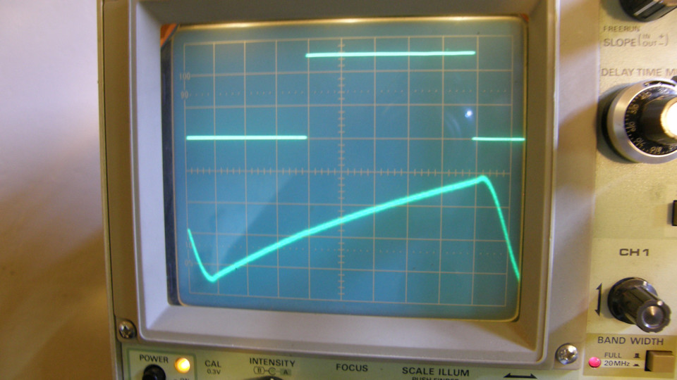
Sync and deflection board during early testing - As of 20190522 In the photos above you can see the deflection boards during early testing. In the second photo, we have the current probe looped into the horizontal coil circuit and the resulting waveform on the o'scope. You can clearly see the capacitor substitution box being used to dial in the exact value to get a good clean scanning wave form. The upper trace is the HOT drive square wave and the lower trace is the scanning current running just about +/-1 Amp. Perfect! Just a side note for you. Visible in photos 1 & 2 on the scan driver board. The HOT driving transformer is a common 600Ω center tapped to 600Ω center tapped audio coupling type. It is the handsome black cube with the writing on top near the HOT. I used this particular one simply for its cool appearance! I have whole bunch of cheapo units that are bright red and look like transistor radio audio output transformers. I think they were made for computer modems. They just didn't appeal to my eye! But, they would work just as well and will have to be used in future projects because I have no more of these nice black potted units. This completes the assembly of the two main circuit boards for the project. In the next phase, [PART 4], we modify the high voltage module and actually get pictures from the dissector tube! REFERENCES: 1. PDF file [ITT F4012 Image Dissector Tube ] from around the late 1960s? 2. PDF file [LM1458] dual operational amplifier in 8 pin DIP package 3. PDF file [D43C1] PNP power transistor in TO202 package 4. PDF file [LH0101] 60W high power opamp 5. Basic64 / Text file [SYNC_ROM.bas] Source code for creating the Sync Generator flash PROM 6. Basic64 / Text file [IMGx8_ROM.bas] Source code for copying eight 256x256x8 image data files to the flash PROM [HOME] [ELECTRONICS PROJECTS] [PART 1] [PART 2] [PART 4] |