| LabGuy's World:
Weird & Rare Video Equipment Collection:
New Addition 03.01.26 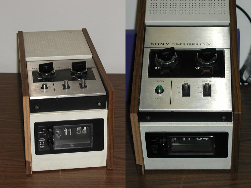
197?: Sony TT-100 Television RF receiver and RF modulator! Vintage: late 1960s? This is a stand alone television receiver capable of picking up (U.S.) VHF & UHF channels. It is also an RF modulator for playing back video on a television set. This unit would have been the compliment to the first generation Umatic VCRs. Some of the Umatic VCRs had built in receivers. for the VCRs without receivers, this was the perfect add on. It allows for the all too familiar time shifting of programs by way of its built-in mechanical digital clock / timer. When the desired time was reached, AC power was engaged to the recorder. This means that the VCR had to be the mechanical kind, so the user could put the mechanism into record with the power off. Clunky, but usable! What a wonderful artifact!!! New Addition 02.09.27 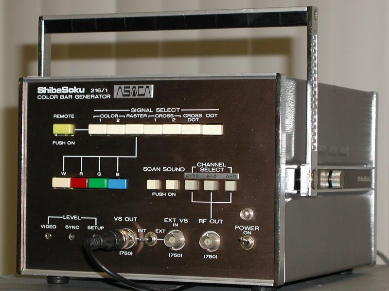 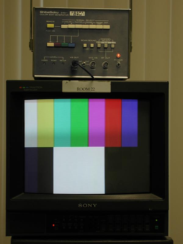 
197?: Asaca (ShibaSoku) 216/1 Color Bar Generator! What ever became of Shibaden, LabGuy? I'm glad you asked! Shibaden sold their VTR division to Hitachi Denshi around 1969 or 1970. Then Shibaden changed the company name and set off to make[ broadcast video recorders], broadcast video cameras and broadcast test equipment. This is a field in which they are still top players today. Mostly in Japan. This is one of their earliest pieces of test equipment. A very nice, compact, high quality, color bars, cross hatch and dots generator. These are used in the alignment of video monitors and other ancillary pieces of video equipment. Be assured this is more than a collector's item. It is also quite useful! Though not up to true SMPTE or IEEE standards, this is still an adequate instrument for the things that LabGuy works on! Needed: Nothing! I've got both operator's and service manuals for this unit. New Addition 02.03.11  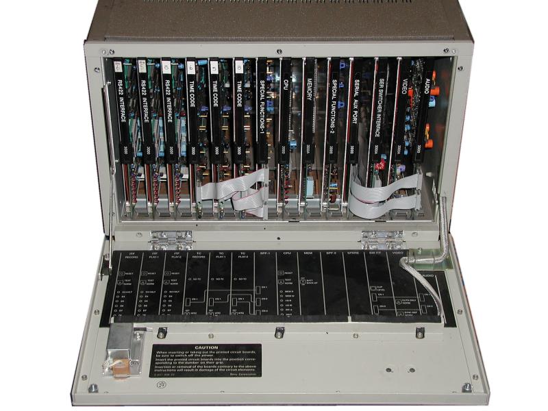 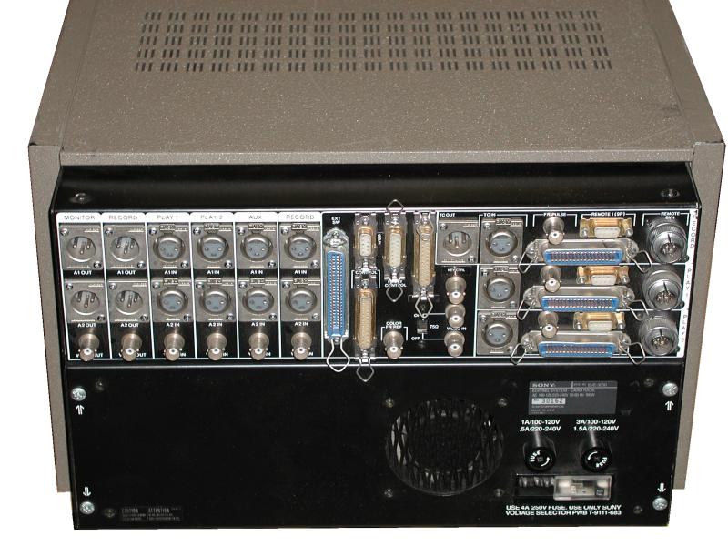
1984: Sony BVE-3000A Editing Controller! Now, why would this thing excite me so? Probably because I personally tested and aligned this very unit at the Sony Tech Center, located in Palo Alto California. That's why! My original test stamp (#80) is still on several of the PCB's in this unit. This feller is in sorry shape cosmetically. But, that should not prevent it from working. I will need to round up a set of VTRs before I can test it, but with my connections, that should be no problem. The first photo shows the control console. This was attached to the main unit by a 25 conductor cable. Both units are self powered from AC. The left side of the panel controls the players and the right side controls the recorder. The operator or editor enters the desired in and out points for one or both playback vtrs. Next, the operator sets up the in and out point, whether to insert or assemble edit, selects what type of video effect (cut / wipe / dissolve / etc.), how long the effect will last, and so on. The central portion of the console is a specialized calculator that helps the operator to make complex edit decisions. All in all, a very fancy system. We won't mention that the modern equivalent of this system now fits in your shirt pocket and talks to the decks by digital infrared beams. . . . An edit controller is a kind of specialized computer. It is attached to two or three VTRs. One or two players and at least one recorder. All digital dialog is over either a dedicated Sony link or the more general purpose RS-422 link. Looking at the center photo, the first three printed circuit boards (PCBs), going from left to right, are the machine communications processors. The next three cards read or write time code information to / from the VTRs as necessary. Next, cards six through nine are the general purpose computer section of the controller followed by the general purpose serial communications port (Yes! an entire board for one serial port!). The last three boards form a broadcast quality audio / video effects switcher. It can switch between sources, dissolve between them and even perform several different wipe patterns too! All with audio follow, or not, as the Editor sees fit. The computer in this unit is a venerable Intel 8085 running at 2 Mhz with less than 64K of ROM / RAM (combined) memory! The RS-422 boards each have a 4 Mhz Zilog Z80 on them at least. The edit decision list (EDL) could be dumped from this unit to (are you ready?) punched paper tape! It was the medium of the day through out the late 1970s and early 1980s. Is that cool or what? 
The Sony Tech Center Gang getting ready for the company picture in 1984! This fourth photo is of all my old friends, and you know who you are, at the old Sony Tech Center in Palo Alto California in 1984. Where are you all now? Sadly, the tech center is no longer located at this site. If you recognize yourself in the photo be sure to write and say hello. All of these people were involved with the BVE-3000A production or engineering and this is not even everyone possible! I placed a convenient arrow in the picture for those of you who are struggling to figure out just which one is LabGuy. . .(Groovy shirt, LabGuy!) Needed: Complete Service Manual. New Addition 01.12.01 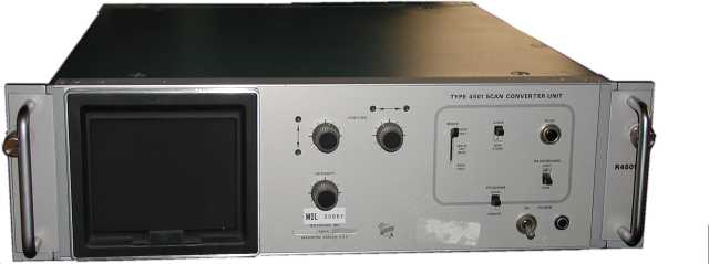
197?: Tektronix Type 4501 Scan Converter Unit! Vintage: late 1970s? Here is a true weird one! As far as I can tell, by simply looking at it, this is an analog storage CRT based, monochrome X-Y-Z vector to EIA raster scan converter. What does that mean? Think of a high speed Etch-A-Sketch with a video output! It can also display in real time or freeze and store an image for some longer length of time. Looks fully operational, though I have yet to test it. Needed: Service manuals for this guy. New Addition 01.11.12 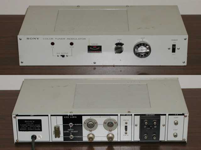
1968?: Sony TUM-100 Television RF receiver and RF modulator! Vintage: late 1960s? This is a stand alone television receiver capable of picking up (U.S.) VHF & UHF channels. It is also an RF modulator that takes in composite video and one channel of audio and puts them out on an unused VHF channel. Usually channel 3 or 4. We would take something like this for granted today, since these functions are standard on even the cheapest home VCR! Not so back then! From the seriousness of the audio connectors, this unit was probably intended to be used with the EV series of one inch VTRs from Sony. Needed: Service manuals for this guy. New Addition 01.09.06 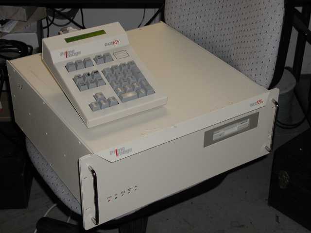  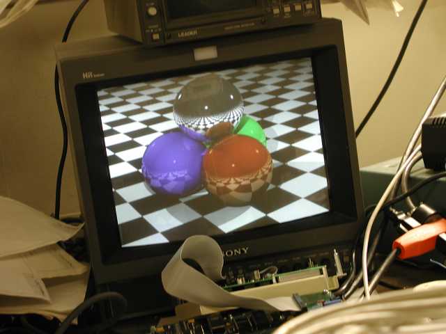
1991: Prime Image "accESS 500" Broadcast Video Still Store! Vintage: April 1991. I know this for a definite fact. Because, I designed the core of this product. Yep, this is my baby! When this product was introduced, ten years ago, it sold for $11,000. I just got one for $50! Now, that's what I call depreciation. The accESS 500 product was nominated for an excellence in engineering award, by Broadcast Magazine, at the 1991 NAB convention in Las Vegas. At the company dinner, when the product was unveiled to the sales representatives, it (and I) received a massive standing ovation. After my wedding, it was the second proudest moment of my life! There were three other engineers involved on the accESS 500 project as well. They were: Keith Moeller, Chris Gifford and Bill Batty. Keith and Chris worked on the analog circuits portion and Bill was in charge of (glue logic) FPGA designs and primary applications software design. Ultimately, Bill ended up designing the TBC section of my boards as well. The analog boards, designed by Keith and Chris, were able to accept video input in any one of four video formats. These were; Composite video, Component (Y/Cr/Cb) video, SVHS (Y/SC) video and RGB video. All four of these video formats were always available simultaneously as outputs. The frame grabber video input and output was Component (Y/Cr/Cb) only. I designed the color video frame buffer boards with A/D's and D/A's, designed the motherboard hardware interface and wrote all of the hardware level drivers. The frame buffer was only half a megabyte organized as a 512 X 512 pixel array. Not a lot of memory today, but an extravagance back in 1991! The video was organized as Y/Cr/Y/Cb arranged into four byte / two pixel packets representing 4:2:2 encoded component video. The first photo is of LabGuy's World's unit. The second photo is the 1991 press release photo that I have kept in my files all these years. Observe, in the second photo, that the remote control has that "unfinished", prototype look. When I fired up my newest toy, I discovered one of my original test images, seen clearly in the third photo, was still on the hard drive! This image is entitled "the stack" and was one of the example files provided with a public domain ray tracing program called, "Vivid". This image was placed in this unit, during system test, by one of the technicians at Prime Image, shipped with the unit and was retained by the previous owners, the Virginia Medical University! A still store is essentially a video recorder that can only record and playback one frame at a time. The number of frames it can record depends on how large the hard drive is. Broadcasters and video producers use still stores to provide backgrounds, inset images and titles into their productions, for instance. Another use is to archive images of people and places for news departments too. This accESS 500 still store can store 200 broadcast quality still images on its internal 105 MB hard drive and display them in several ways. Each still can be called up independently by the operator or stills can be arranged in a list file that simulates a tray of slides for pseudo random playback. Two stills can be copied onto a standard IBM format floppy disk for transfer to another still store, for archival backup or for further processing on a computer. The video data is NOT compressed in any way and yet only requires half a megabyte per image. This was a selling feature at the time. Back then, if you mentioned "video compression" near a professional TV person you would get your ass kicked! Today, virtually all broadcast video is compressed and uncompressed data is a dirty thing. How times change! COMING SOON! The Whole Story. The story of the birth of the accESS 500 will be told by yours truly, along with many accounts from some of the key players in its history! Stay Tuned!!!  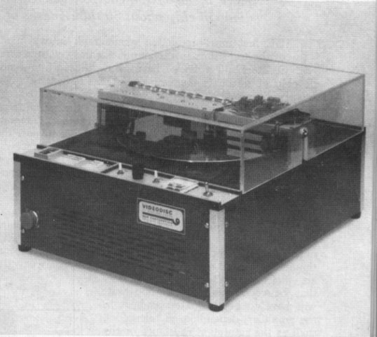
My model 100S-2A & Historical Photo. I was given one of these a few years ago and since then it has collected dust on a shelf in my living room. I had no idea what the story was behind it. But, it did look great! It turns out to be an instant replay video recorder, made by MVK Corp. of Mountain View, California back in the late 1960's. One of the first of it's kind, a real historical artifact! The following is the text that accompanied the historical magazine photo: . A portable magnetic disc recorder is now widely used by U.S. and European television networks to insert instant video replays, including stop action still pictures, into live sports telecasts. This recorder has now been adapted by it's manufacturer, MVK Corp., for broad range of scientific, medical and industrial applications. The new device stores up to 20 seconds of signals from a live TV camera on the top surface of a 12 inch aluminum disc coated with a nickel cobalt recording medium. The 20 second recording can be immediately played back for the TV audience as a continuous sequence or as stop-action pictures. Cycling from record to playback requires 1/5 second. (From Electronics World Magazine - December, 1966) New Photos! 020415 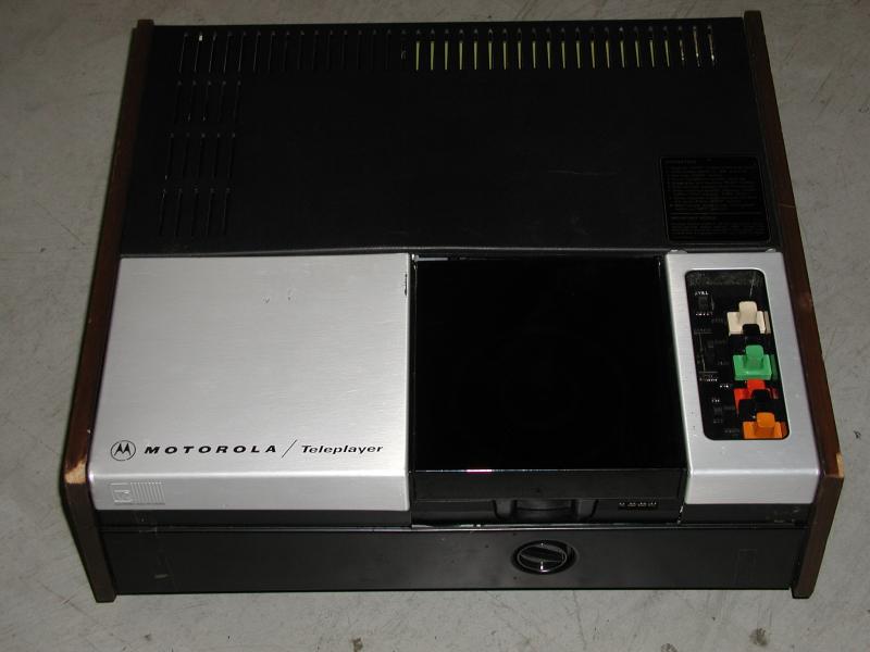 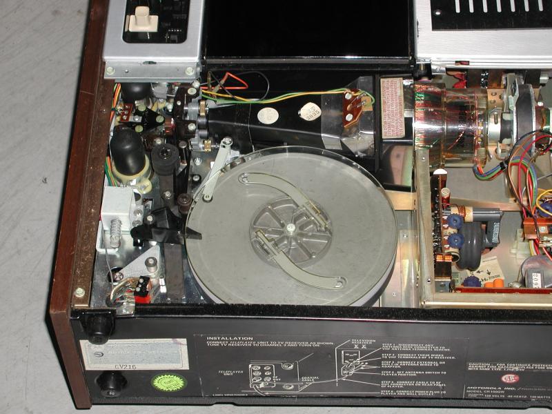 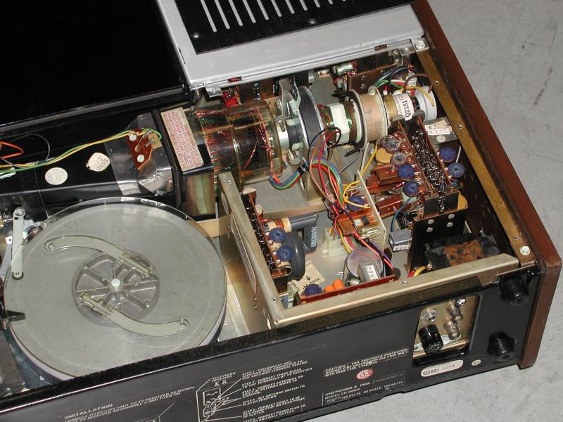
Motorola EVR Video Film Player tech details. The EVR System, which stood for, Electronic Video Recording, even though it couldn't record! A photographic film based, video play only system. EVR, developed by CBS in 1967, was the brainchild of Dr. Peter Goldmark, developer of the CBS field sequential color TV system, the Chrysler Highway Hi-Fi. and the 33-1/3 RPM Long Playing (LP) record. LabGuy's World has obtained this unit from ebay. The original unit, from my collection, had turned up missing! Lost in a move? Stolen? Who knows? But, once again, I have an example of this marvelous system. Now, does anyone have any films? I can probably transfer them to tape for you! In the first photo, we see the machine in all its splendor. The second photo is a detail shot of the film path. Film traveled downward, in the photo, past the scanning region, through the capstan and pinch roller and ultimately ended up in the take up reel. On the left side of the photo, the two photomultiplier tubes can be seen. They are the black dome shaped assemblies. In the third photo you can see the scanning CRT with all of its scanning coils, focusing and centering magnets and all. This tube contains an ultraviolet short persistence phosphor which is optimum for this type of service. (See my description of flying spot scanning in the following section: B&K 1077 TV analyst). Electronics of the late 1960s was nowhere near the state of the art that we enjoy today. In fact, this unit contains three vacuum tubes! However, that didn't deter the engineers from tackling the design of some incredibly complex consumer products back then! Besides, Dr. Goldmark through his work on mechanical television was never able to kick the "wheels and gears" habit. . The following text comes from a November, 1967 issue of Electronics World magazine: CBS TV FILM DEVICE - The recent announcement by CBS Laboratories of a new TV recording system does not concern a new type of video tape recorder, but consists essentially of a "super 8" size movie film which is electronically scanned and converted into video signals. The master film can be prepared from video tape, movie film, or live pickups and a number of prints are then made which can be used for viewing on TV sets. The outstanding features of the CBS development are the use of new, strong, flexible and extremely thin film material, similar to magnetic tape, but containing movie pictures of great resolution. Unlike movie films, the new CBS film moves continuously, without the pull down and shutter effect, and without sprocket holes. The optical transducer for the TV playback device apparently consists of a light source and photo pickup. While CBS had not divulged the exact method of playback, a type of flying spot scanner, such as used in TV studios, could provide the means of transducing the photographic pictures into video signals. Synchronizing the information, in the form of black and white markings along the edge of the film, can provide the frame by frame synchronization. For the reproduction of color pictures, two separate frames, side by side on the film, are used. One frame contains the "black and white" picture content while the other frame provides the color information. This is compatible with the present color TV system where the Y signal contains the brightness information and the color subcarrier contains all of the color information. The actual pictures are much smaller than standard 8-mm movies. Good resolution is obtained by using microfilm techniques. An added feature of this new CBS development is provision for stereo sound, which is also recorded on the film, somewhat similar to the sound track used in 16- and 35 mm sound film systems. The CBS system is intended primarily for educational TV systems where a film is played at a central location can be viewed on TV monitors in different classrooms. For the home entertainment market, the attractions of this system appear somewhat limited. It is now possible to rent or purchase sound movies at relatively low cost. Even if the cost of the CBS playback device is brought down to the projected $270, this is only barely competitive with film which can be viewed on a large screen, rather than from the face of a TV tube. At the present time, CBS is still conducting tests, mostly in school situations in England and does not plan a full scale demonstration of the system in this country (USA) until April of next year. We can conclude that video tape recorders are here to stay and that their eventual application to the home market will not be impeded by the CBS labs development. This development may, however, provide a valuable addition to educational TV and to some other applications where the use of microfilm techniques, combined with TV viewing, will offer a substantial advantage. ~END~ . 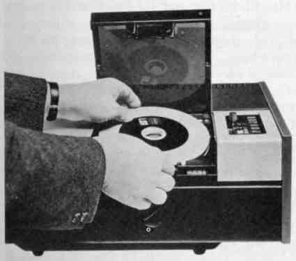
An example of EVR in use. You should see how clever this thing is! It's extremely cool! I'm glad I own one. How much luck is it, that the one I got had about 500 feet of film broken off and still residing on the internal take-up reel? The picture shows a lot of technical details. If you would like more info, write to me! The system used a flying spot scanner to reproduce the image from a special dual frame film, which was contained in a single reel cartridge. One frame contained Luminance data the other, contained the Chromanance. The CRT was raster, which is ultraviolet by the way, was separated into two side by side copies allowing both frames to be scanned simultaneously. Each frame was then picked up by it's own Photomuliplier tube. All in all, this machine contains three vacuum tubes. . There are a lot of these machines on the surplus market still to this day. Has anyone got an advertisement or sales brochure for one of these? Does any one know Joe Kennedy? He was the fellow, who I met many years ago, who had several thousand of these machines. Tell him to contact me, please! B&K Television Analyst Model 1077B! UPDATE INFO & PHOTOS! 03.01.26 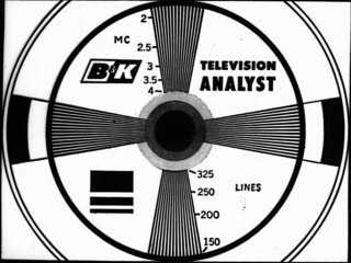 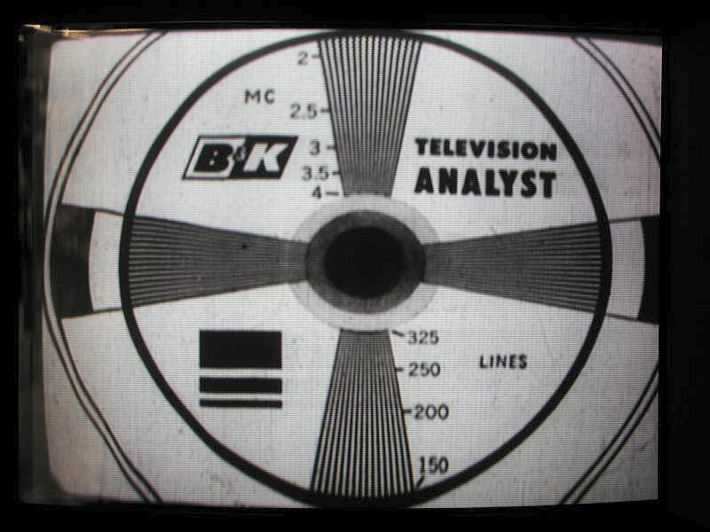
1077B "TV Analyst" Test Pattern Slide and Screen Shot. These were used in tv repair stores and high school electronics classes. A product of the early 1970s. They were be used to test many of the television receiver's subsystems, such as: the tuners, IF stages, video amplifiers, high voltage power supply and deflection circuits. The 1077B as also an excellent teaching tool. All in all, this is a fabulous piece of gear! The best part was the test pattern generator! The second photo, above, is a contemporary shot of the 1077B video output as displayed on Sony broadcast quality monitor. The vertical linearity distortion is occurring in the 1077B, and not at the monitor. Such is the result of tube circuits and old dried out capacitors. Stay tuned for restoration updates as time permits! 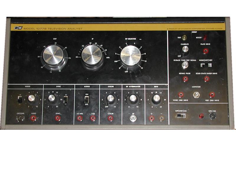 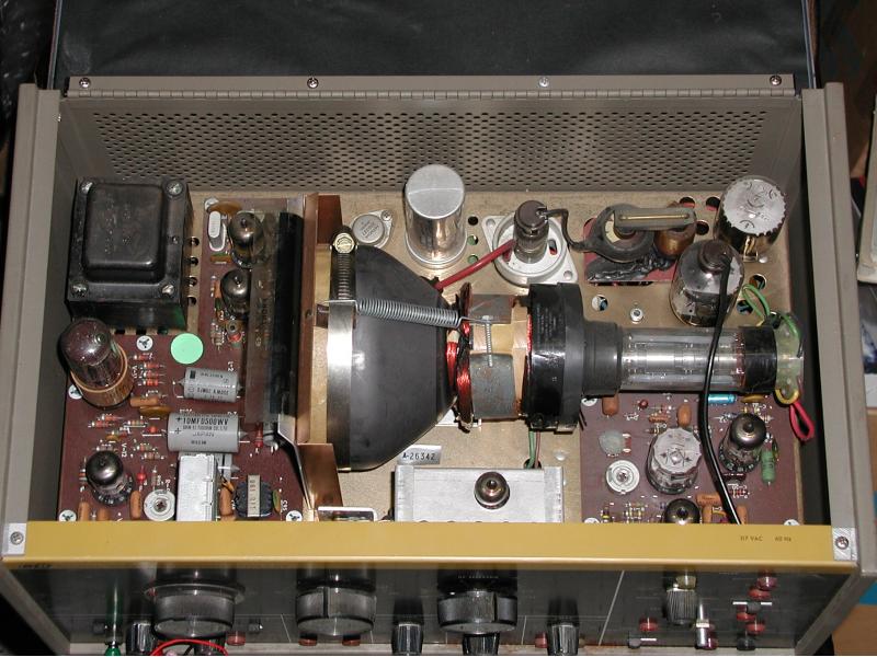
Front and top views of the 1077B TV Analyst. (New photos 03.01.27!) The B&K television analyst is also a "video camera" of sorts. At the least it's a "video source". It contains a clever system called a Flying Spot Scanner, or FSS . An FSS uses a 5 inch diameter CRT (Cathode Ray Tube), visible in the second photo above, and a PMT (Photo Multiplier Tube) visible on the left side of the same photo. A transparent slide, visible in the photo below, is pressed tightly against the face of the CRT. The CRT is scanned with a blank raster. The light from this raster is passed through the slide and is picked up by the PMT where it generates a video signal. This is the method of scanning that was used in the earliest days of television and works extremely well. Another feature of the flying spot scanner is that is elagently simple. Looking in the top of the unit, you can clearly see that there is not much to it. The circuits of this FSS also serve as a source of signals that can be fed into various TV circuits to locate a fault. Thi includes, horizontal and vertical scan signals, raw video and sync and various signals for testing the (radio) receiver portion of a TV set. 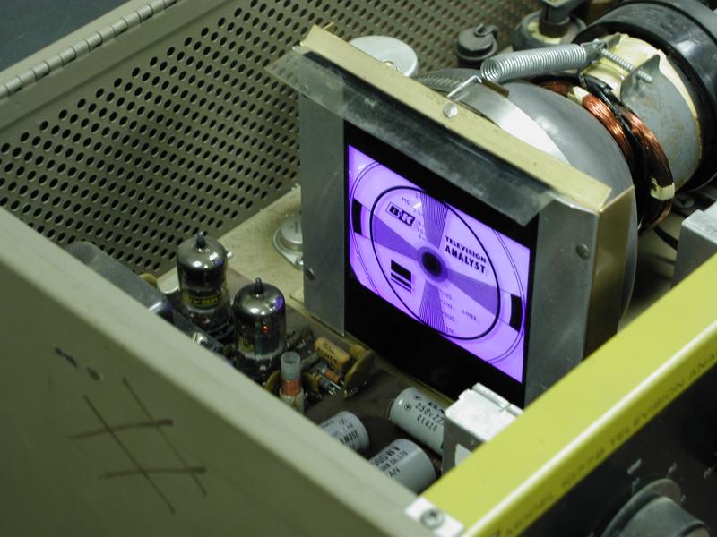 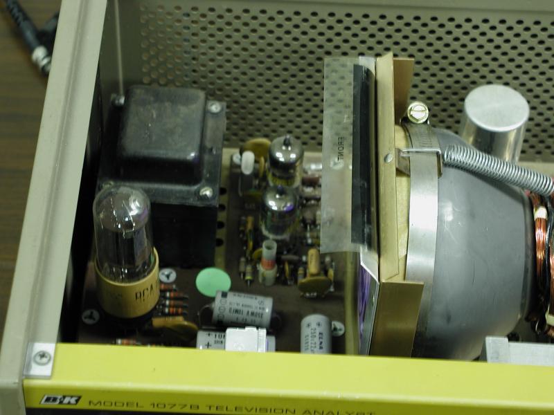
Short Persistence Ultraviolet Phosphor CRT! (New Photos! 03.01.26) The scanning CRT uses a short persistence ultraviolet (UV) phosphor. The test pattern slide pressed to the front of the CRT in the first photo above. The second photo shows clearly, the RCA 931 photomultiplier tube (PMT with the light brown base) directly in front of the scanning CRT. The PMT converts light into electrons and then amplifies these electrons thousands of times. The PMT is more sensitive to UV light than to visible light. This makes for a very sensitive system. The short persistence of the phosphor is necessary to increase the horizontal resolution of the image. NOTE: The flying spot scanner doesn't actually work with the top cover open! Room light over powers the light produced by the CRT. . UPDATE! 03.01.04: Need parts and service on your old B&K Precision test equipment? Then visit this site here: B&K Test Equipment - The World's #1 source for older B&K Precision test equipment, charts & parts. Also specializing in repair & service on all older B&K equipment. They sell slides and tubes for the 1077B and all its variations! The service package that I purchased from B&K Test Equipment lead directly to the successful resurrection of y 1077B! Thanks!!! When you visit their site, be sure to tell them LabGuy sent you! Click here to: Return to the Exhibit Index Return to The Top of LabGuy's World Last updated: January 27, 2003 |