|
LabGuy's World: RCA CRV-59AAE Iconoscope TV Camera Restoration - Part 1
[HOME] [ELECTRONICS PROJECTS] [PART 2] [PART 3] 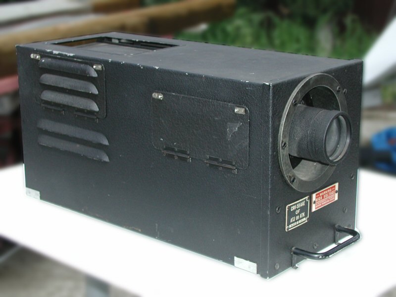
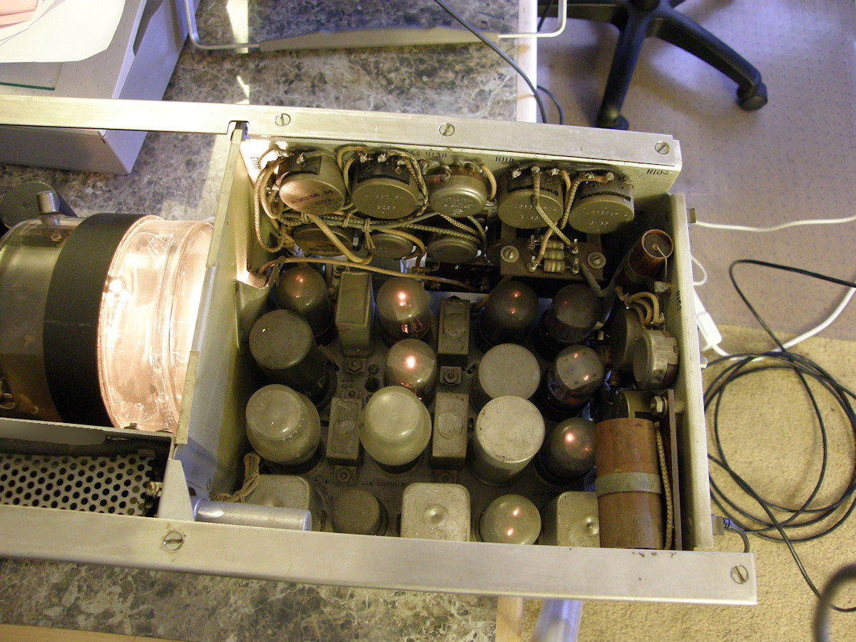
RCA CRV-59AAE Iconoscope Camera - 20150410 Project goal: Get this $600 investment to operational status. It was alleged to be operational in the recent past... ten years maybe? Will find out soon enough if it is a worthy project. Condition is excellent and a mating power supply is also present. Of course, the interconnect cable is missing. The archaic AC inlet connector will need to be updated as well. I can not even identify the darn thing! Fortunately, I received enough documentation with the camera to proceed with confidence. The camera was originally made in 1945 or so. Right at the end of world war two. It was later converted to 525/30 video and a power supply was constructed in 1956 by a Mr. H. E. Fisher of Shawinigan Chemicals Limited. This information comes from a letter, dated May 8, 1956 to Harjo Sales, the seller of these U.S. Army surplus TV cameras at the time. Coincidentally, Another document, the Harjo Sales CRV-59 conversion instructions, are authored by Scotty Fisher, AF4TST. I do not know if these fellows are related other than in business. 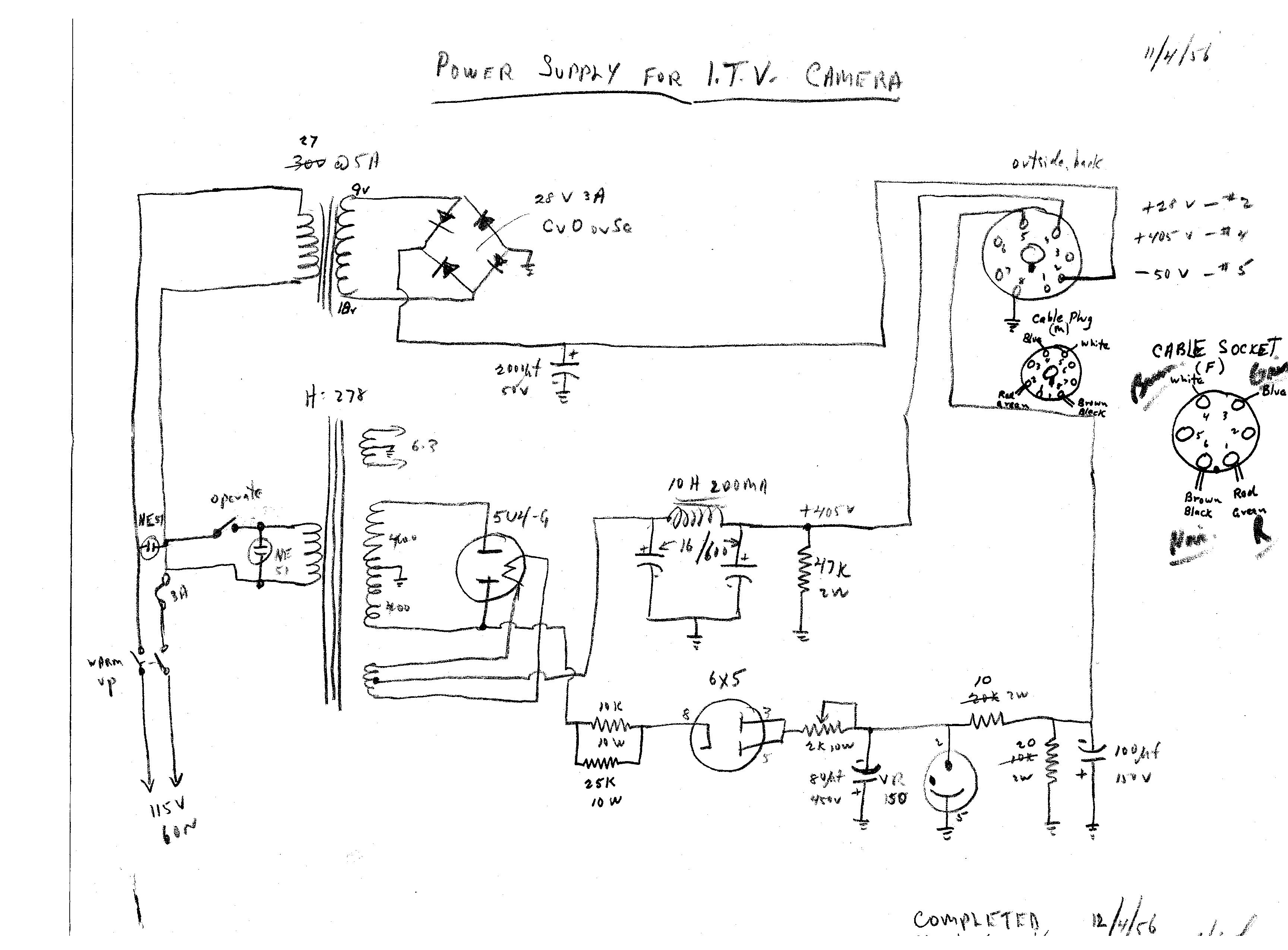
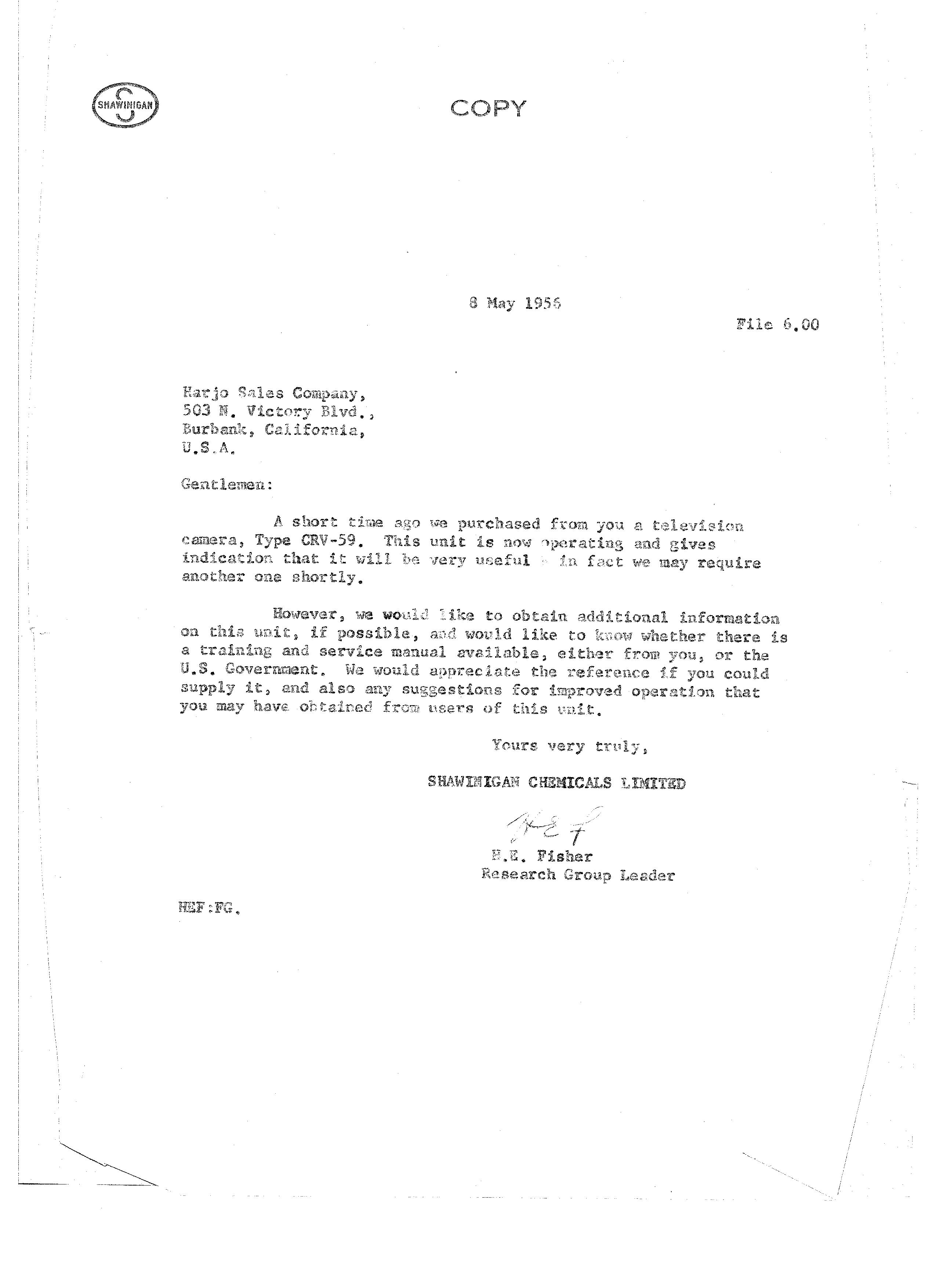
Ancient documents - The mother lode! - 20150216 As designed for the U.S. Army during WWII, the CRV-59 is not commercial TV compatible. Apparently conversion to 525 line 60 fields is easy enough. This one has already been converted. To operate, it requires three power supplies. Twenty eight volts DC at 2 amps to drive the tube heaters, the bias light bulb and provide DC bias for the vertical centering control. The second voltage is four hundred volts DC at 150mA to run the main circuits. Last is a negative fifty volt bias supply at just a few milliamps. So, the obvious place to start with the restoration will be in the power supply unit. Mr. H. E. Fisher left a whole batch of notes which explain the modifications he made, issues he encountered and their solutions. Do you think Mr. Fisher dreamed that someone would resurrect his project 60 years later? I doubt it, too. 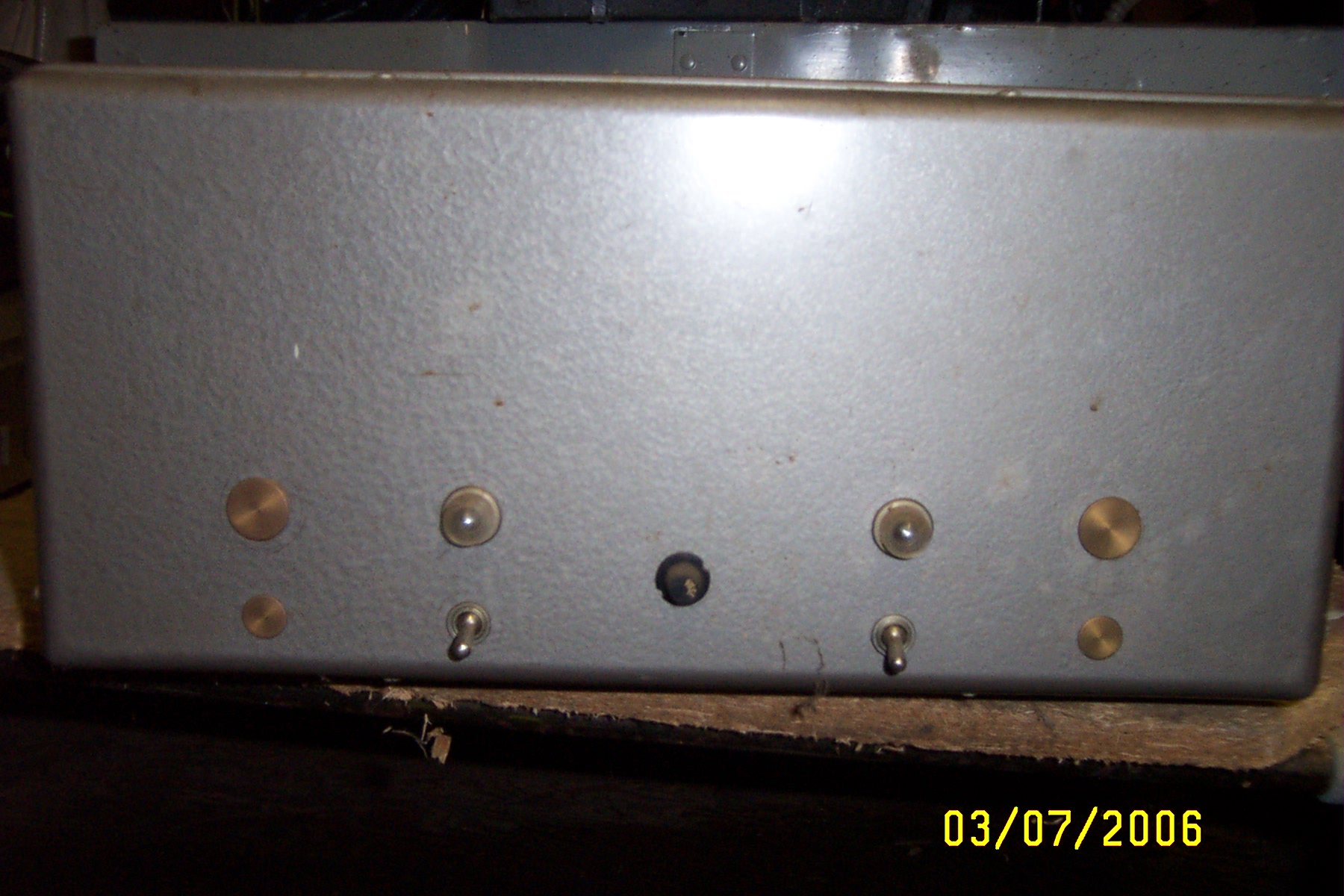
The 1956 TV Camera Power Supply as I purchased it nine years ago - 20150216 I am fully expecting this to come up working. Be the optimist, right? I will acquire an ocatal plug for the DC output and will be replacing the funky AC input connector on this power supply. With the octal plug, I can reconstruct the original interconnecting cable. For convenience, I will be soldering the wires to the pins of the connector on the camera. I have very little hope of finding a mate to that socket and don't feel like replacing it at this time. Ultimately, I will add a proper 525/60i sync generator with genlock capability and a video proc amp for the camera's output. This will make this CRV-59 usable with modern equipment with no risk of frying a sensitive video input with high voltage leakage from the vacuum tube circuitry. For those who wish to get the authentic "look" of 1940s video. In the mean time, fill yourself in with the history of these cameras and other exciting videos on the subject of Iconoscope Television cameras operating today! How RCA's WWII Military Television Development Shaped Modern Warfare (and Postwar Broadcasting) - 20150503 An excellent video by Maurice Schecter a long time fan of television and its history. Here he goes inot immense detail about the program that produced these TV cameras during world war two. A short video introduction to this camera project - 20150503 OK. This is not an operating camera in that video. Yet. If the camera will operate, I will get it operating. Stay tuned. Troy Walter's succesful home built Iconoscope television camera project - 20150503 Troy only recently obtained "first light" from his camera. As you can see, there is some way to go. However, objects and people are easily recognizable in the camera output. The scan issues is caused by using the wrong deflection yoke. A proper 1846 deflection yoke is allegedly on its way to Troy as I type. You can clearly see the outer metal frame that supports the photo sensitized silver droplets on a mica sheet. The back of the sheet is silver plated and serves as one possible output electrode. The collector ring is another. See more at: [Troy's Visual Arts Channel] RAND WWII TELEVISION SYSTEM TEST FLIGHT 1944- 20110607 Link to another enthusiast. Nick Spark is writing the story of the U.S. converted bomber program of the 1940s. Ten minute synopsis of the WWII development program. Many U.S. contractors were involved in this patriotic effort to end fascism. The leader of the pack. The winner! Absolute Best In Show! By Mr. Kenjirou Takayanagi- 20110512 Is that a work bench to die for, or what? What a nice workshop. As you will see, amazing things come to life there. Like the gnarliest Iconoscope camera ever. It demonstrates that Zworykin never saw the full potential of his tube. This fellow makes it look like CCD output! 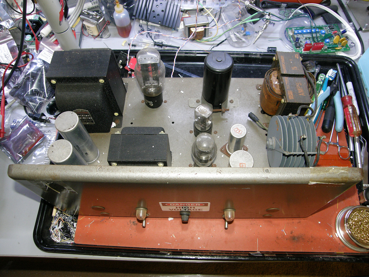
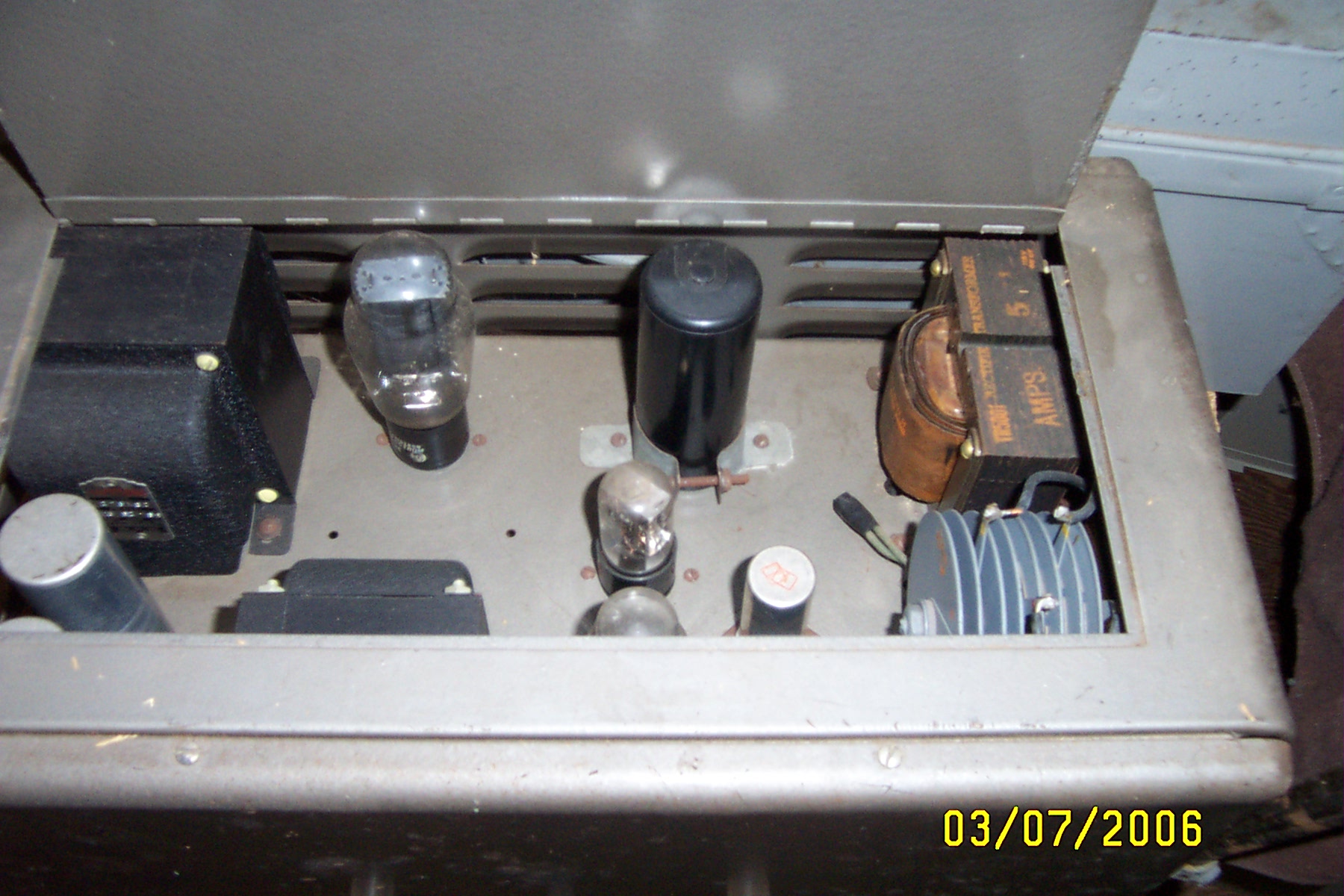
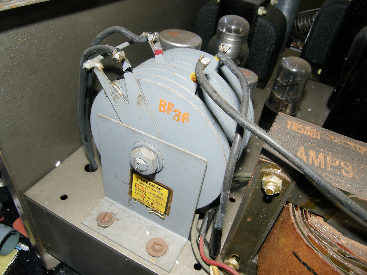
The CRV-59PS Power Supply Today - 20150412 Dig that selenium rectifier right out of The Jetsons! (Lower right) Today, I opened, inspected, cleaned and tested the power supply. The results are that the unit is functional. All voltages present and wrong. This is not surprising. The B+ OFF/ON switch is defective. It is permanently open. I will obtain a replacement switch tomorrow. A temporary jumper was placed across the defective switch and power was applied briefly. No bang. No smoke. Started taking quick measurements of absolute DC (open circuit) voltages and AC ripple voltages. All looked acceptable. I placed the high voltage warning stickers on the unit. 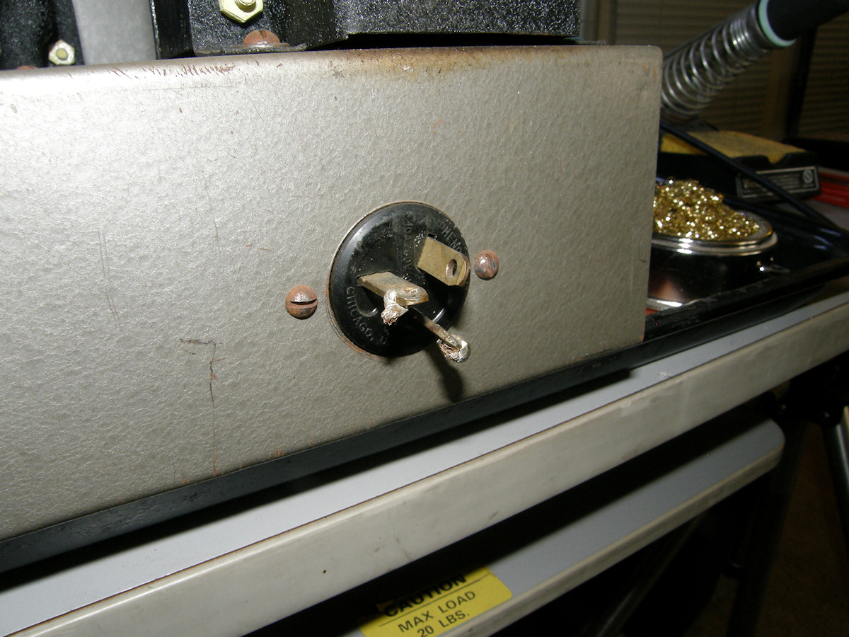
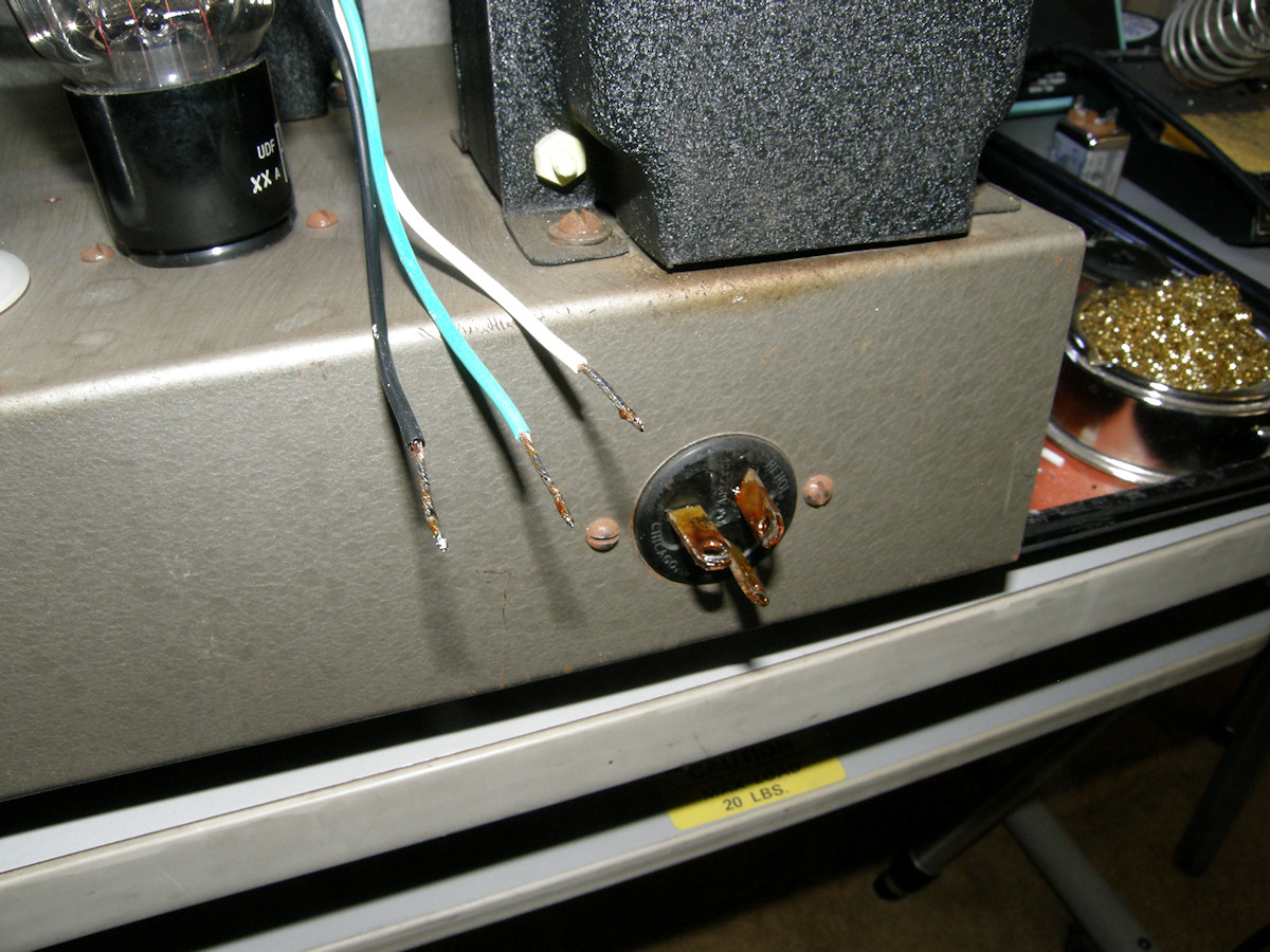
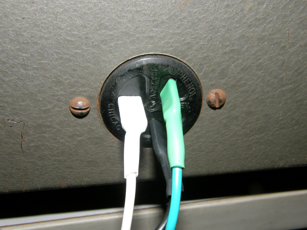
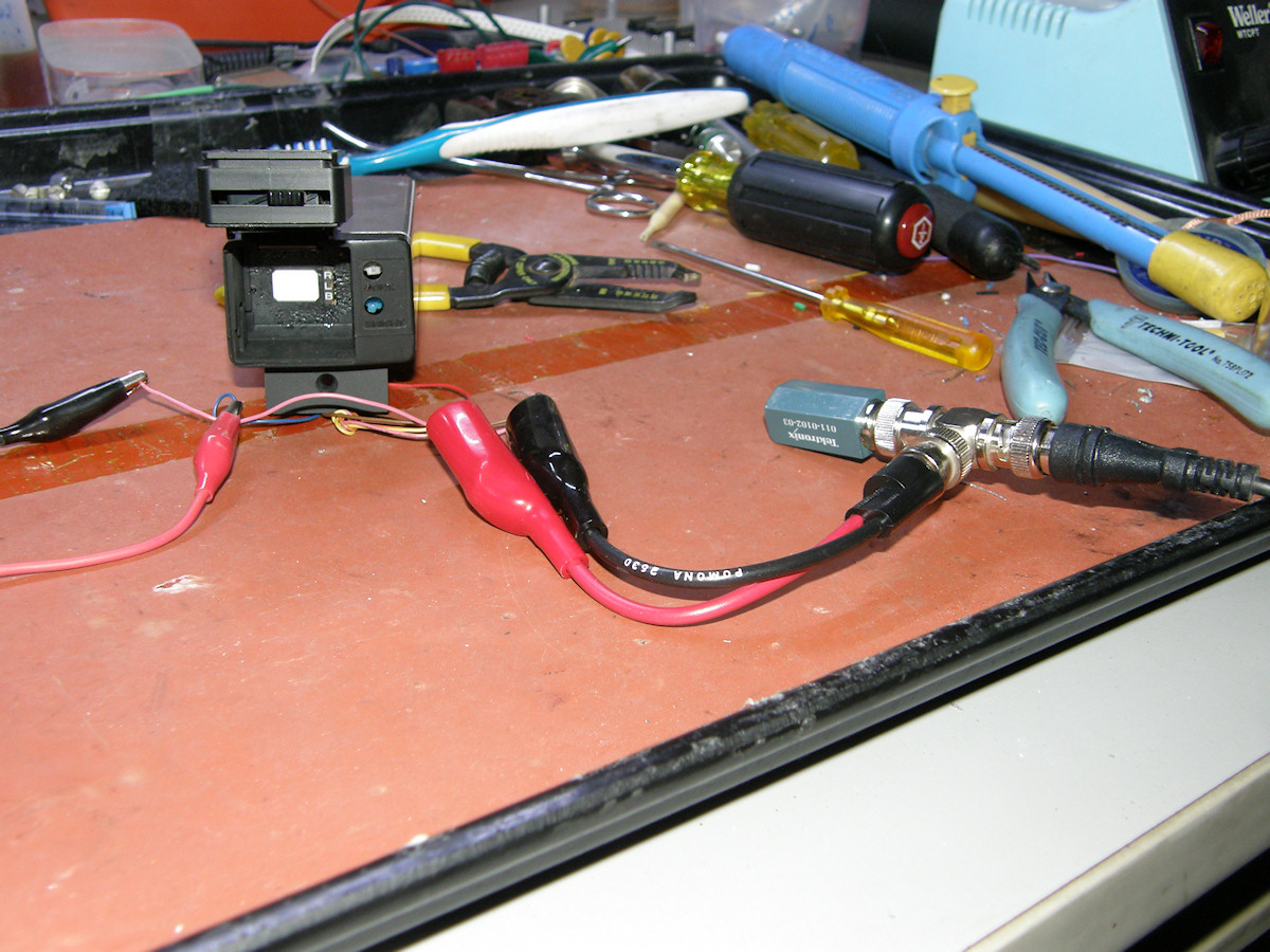
Temporary AC inlet adaptation. - 20150412 I have yet to find an appropriate replacement for this odd ball connector. So, I cleaned the old solder from the blades and attached a proper three wire grounded cord. A bit of heat shrink will be good enough for the testing phase. 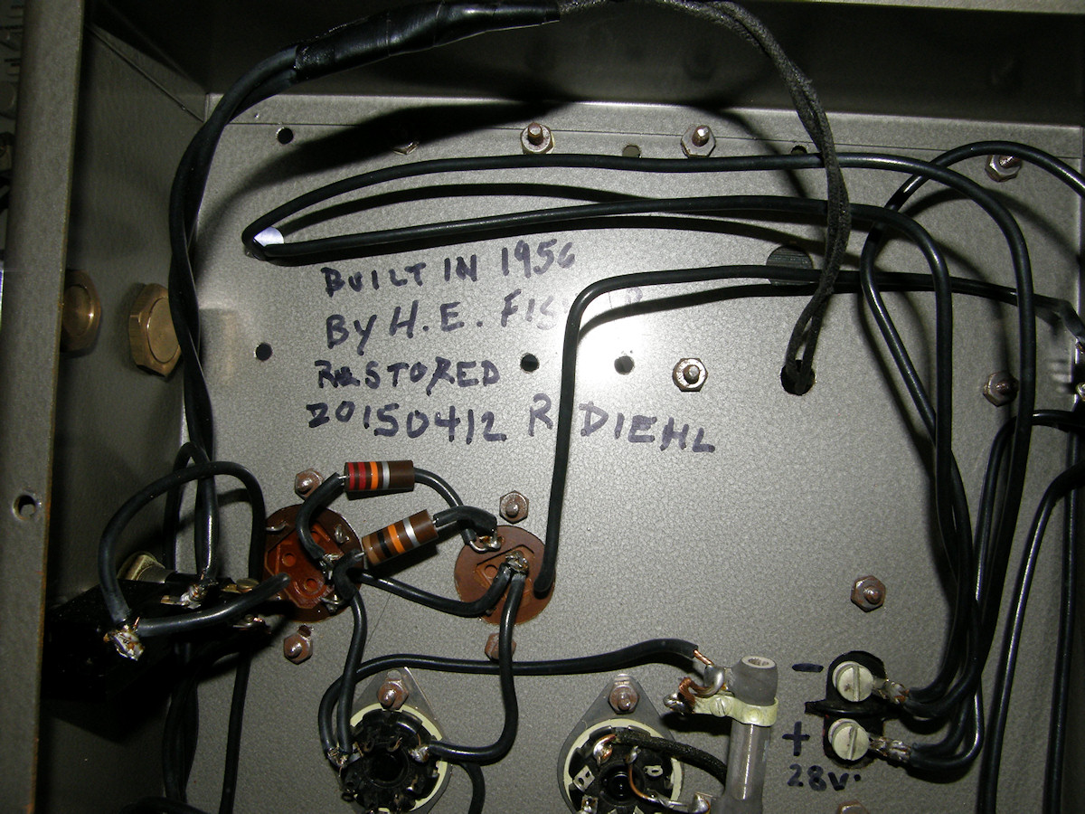
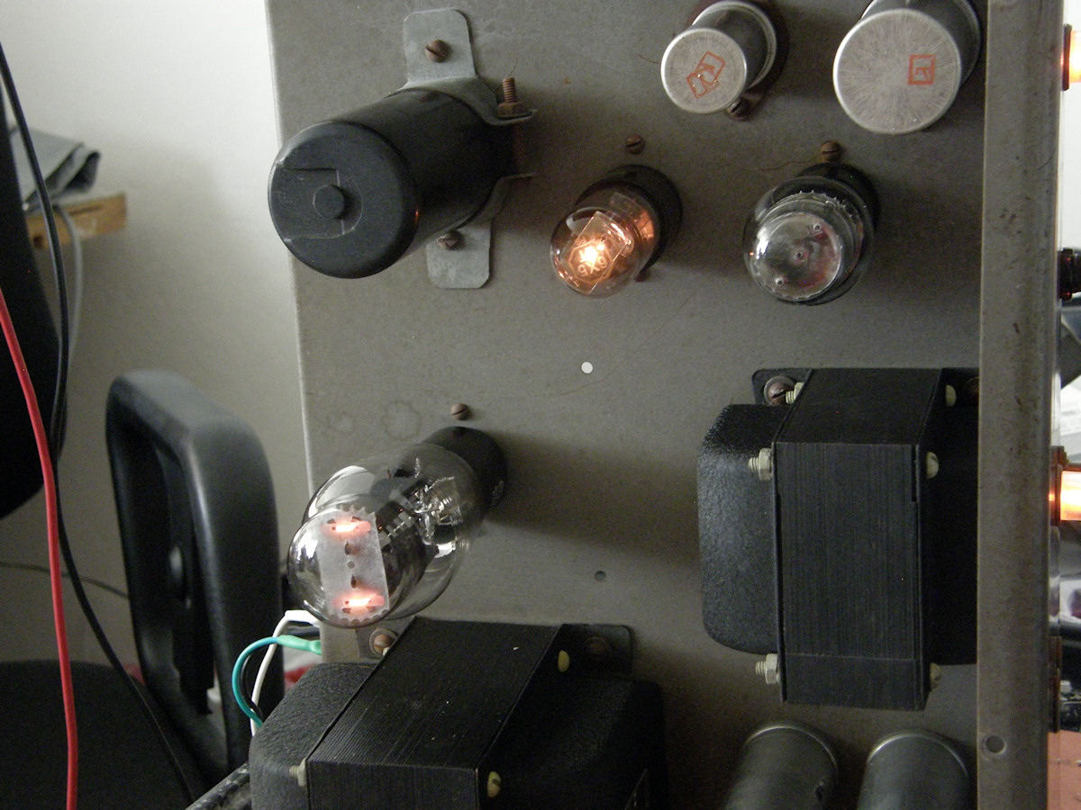
Testing phase. - 20150412 A little sloppy historical provenance for future historians or junk dealers. First glow from these tubes in over a decade. I betcha. The yellow clip lead is the bypass on the B+ OFF/ON switch. 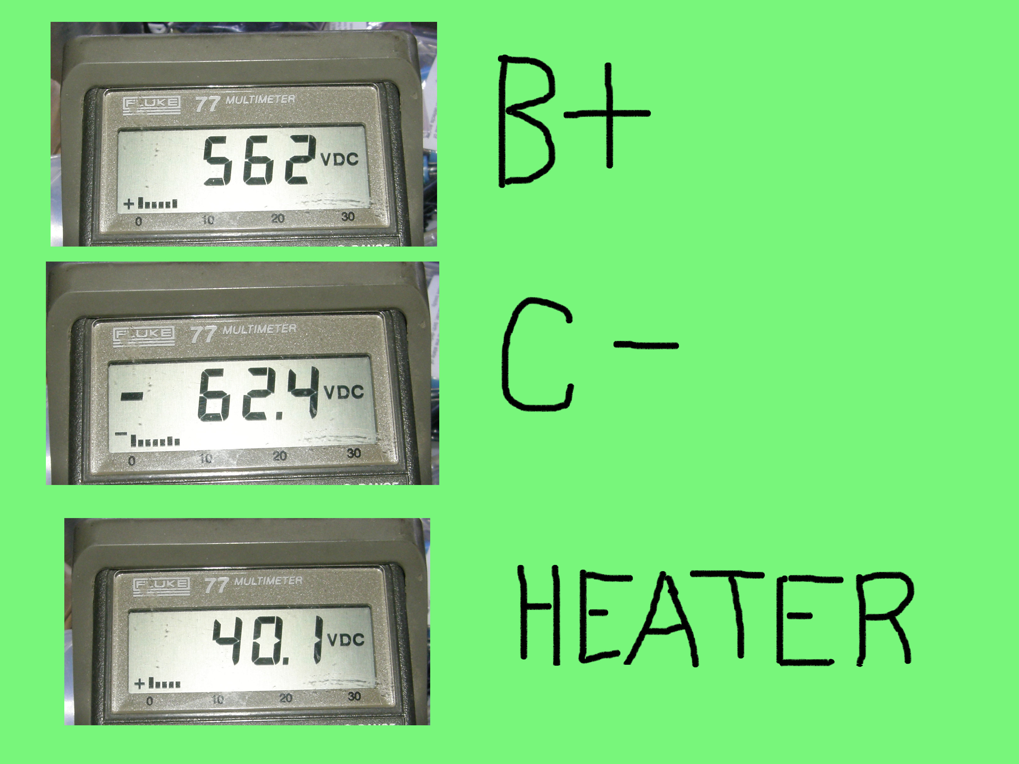
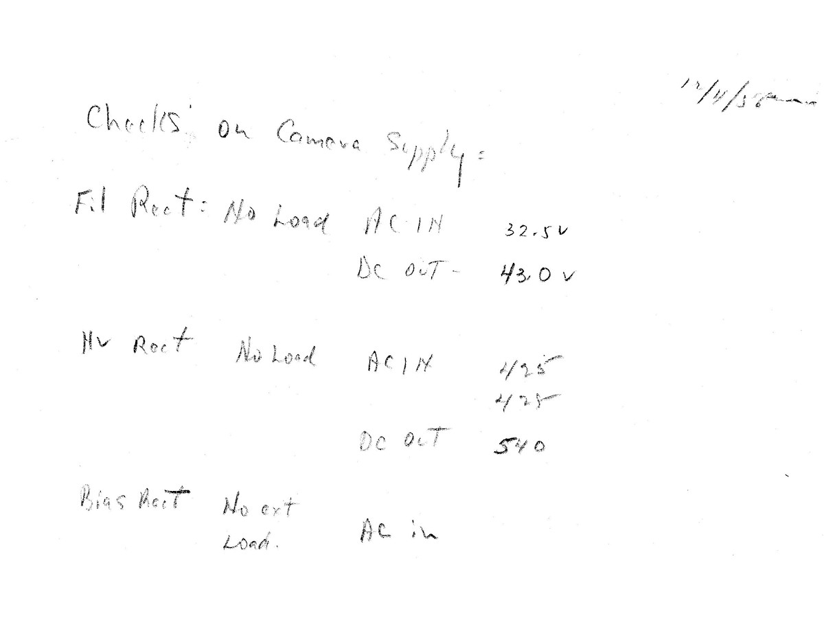
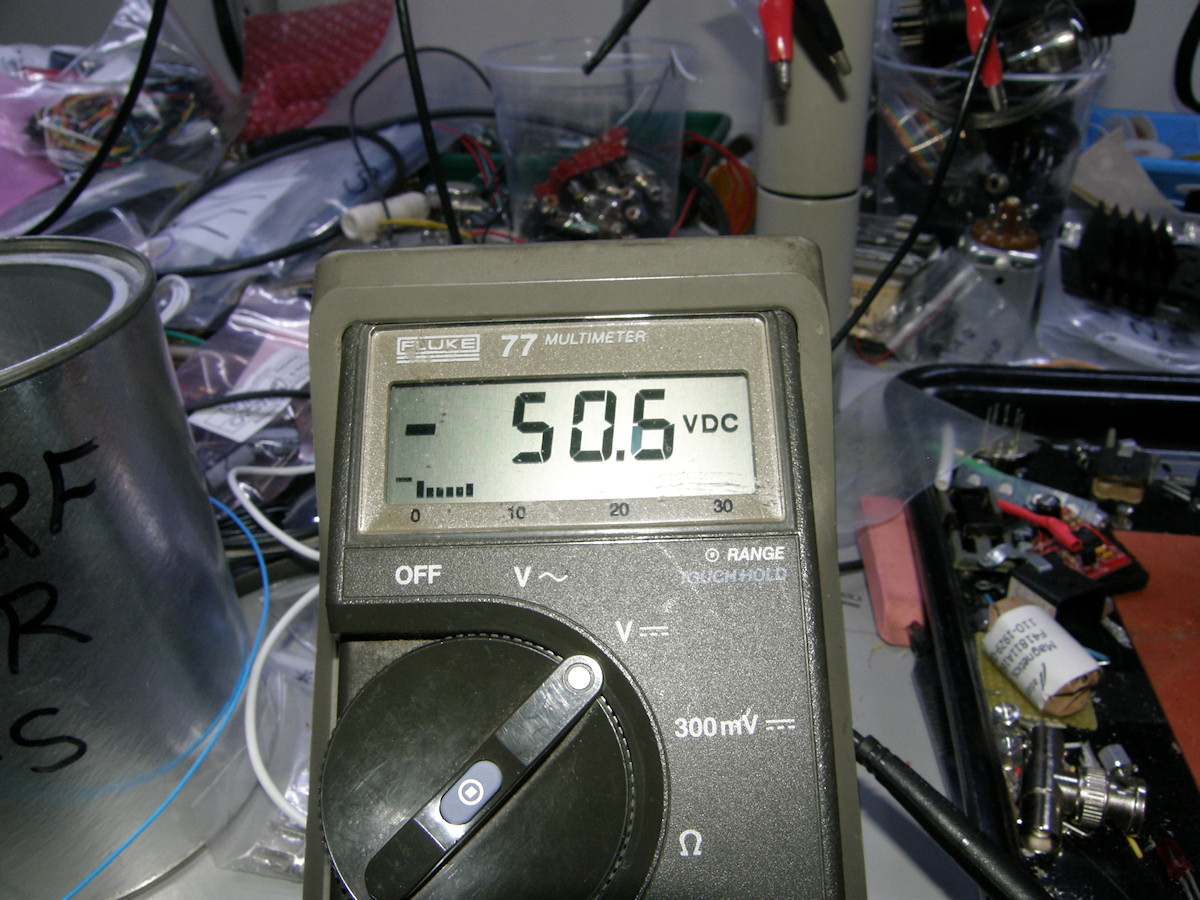
Voltage measurements, no loads. - 20150412 Actual measurements of the three outputs with no loads attached. Mr. Fisher's hand written notes tell us his original results. At least for the B+ and heater. He never wrote down the C- voltage. All other notes show this is supposed to be -50 volts. And I still marvel at the coolest Selenium rectifier I own. The only one too. I think. So, tomorrow its off to Halted Specialties company in Santa Clara for a replacement switch and some appropriate interconnect cable. Stay tuned! 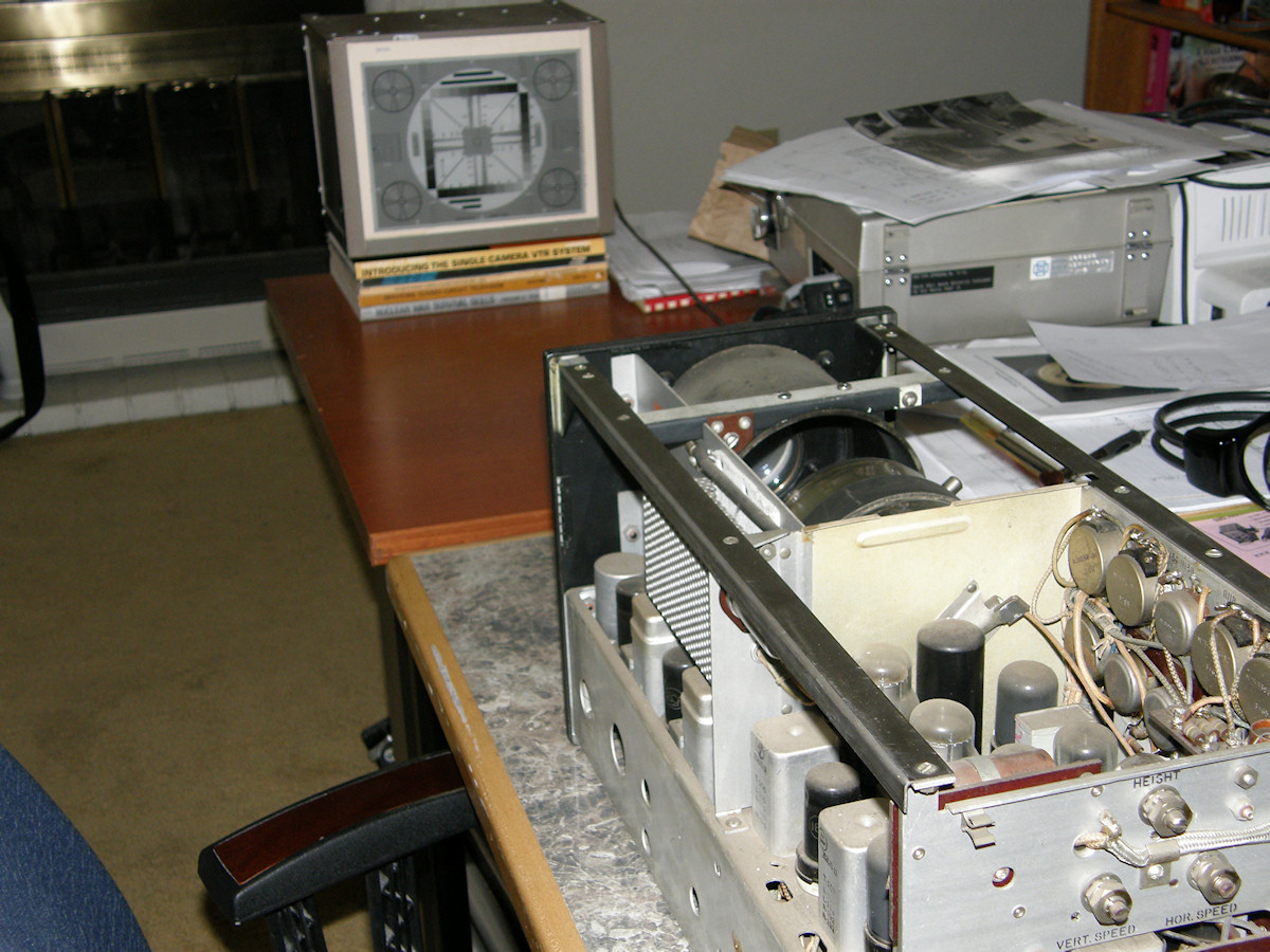
Getting ready for the testing phase - 20150414 Obtained and installed the new switch for the power supply. That works. Begun to arrange the light box and test pattern for the serious testing phase. I am awaiting the delivery of an octal plug for the power cable and then we should be able to start. I thought it was appropriate to use a stack of vintage television camera books to level the test pattern box. To fit into my 1945 post world war two project theme, I've included a copy of "Nuclear War Survival Skills". That, and it was the extra 3/8 inch that I needed to complete the required height. 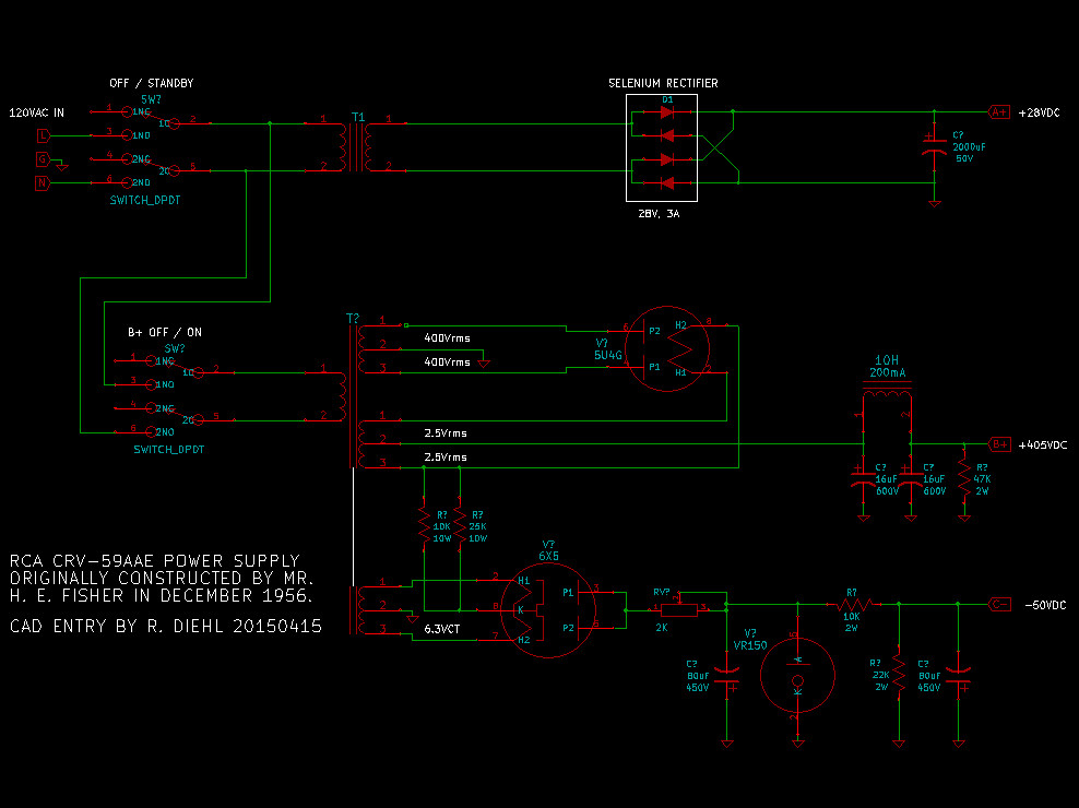
Kicad schematic of the CRV-59 Power Supply- 20150415 Took an hour or so to produce a cleaned up, hopefully easier to read, version of the power supply schematic. Not absolutely accurate on the primary side of the transformers. But, functionally so. The CAD library did not contain the correct switches and I ran out of patience. 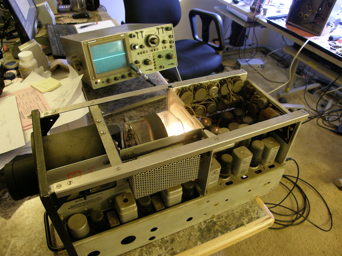
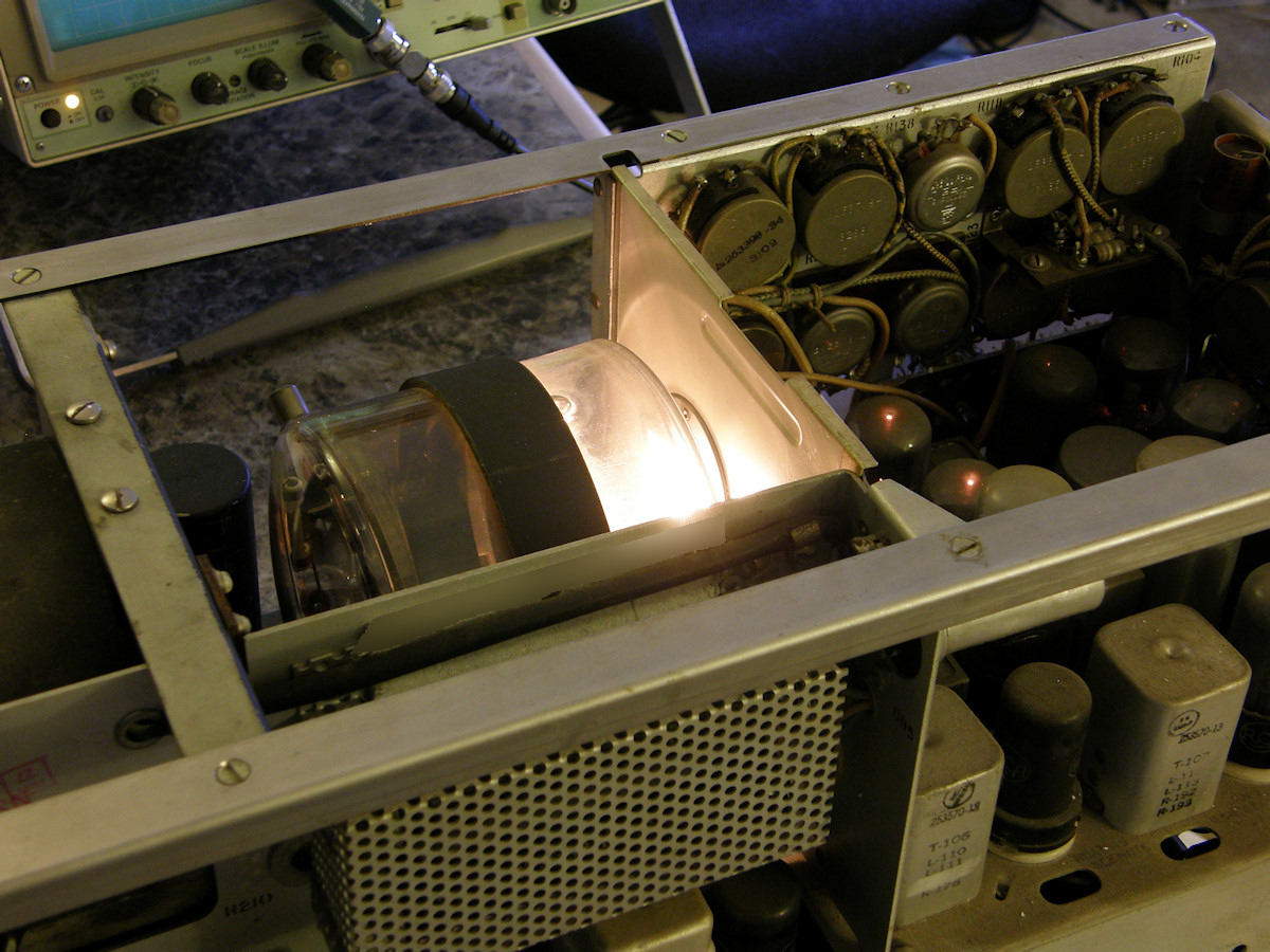
First light... sort of - 20150417 Received the 8 pin octal plug today in the mail. Built the power supply cable. Hooked it all up and turned it on. Nothing exploded nor were there any fires. The first switch turns on the A+ (28VDC) tube heater circuit. The second switch turns on the B+ (+405VDC) and C- (-50VDC) voltages. I turned on the A+ and measured the voltage. Remarkably, it was almost +28 volts DC! The bias light, located behind the iconoscope tube came on nice and bright and the various vacuum tubes started to glow. This is very encouraging! So, I turned on the high voltage. The oscilloscope showed a video-like output for a few seconds then faded away. This will repeat if the high voltage switch is turned off for a few seconds and then switched back on. Initial reading on the negative bias (C-) was not -50 volts. More like +350V. WTF???? (What the Farnsworth?) I will trouble shoot this before moving forward. It is possible that the VR150 shunt regulator (glow) tube is bad or its series resistors have changed value. OR I was simply too tired and probed the wrong point in the circuit. 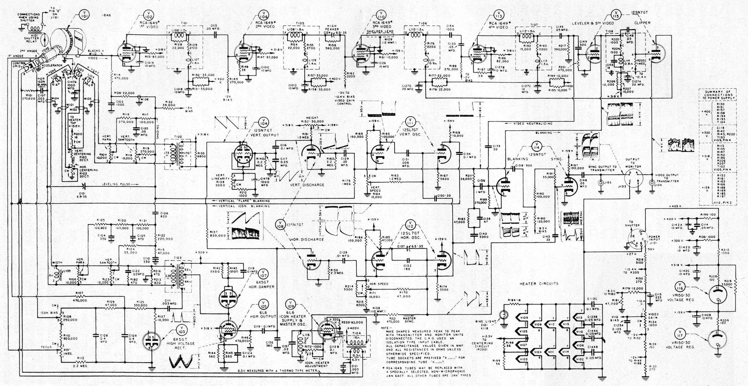
High Resolution CRV-59AAE Miniature Airborne TV Camera Schematic Diagram - 20150417 It has been a long day and this was a good break point. Will return to it tomorrow. In the mean time, you may enjoy a nice high resolution schematic diagram of this camera. State of the art for 1943! Though electrically accurate, these kind of "spaghetti" schematics irritate me. It is done to get everything onto one page. I may create a CAD schematic of this circuit drawn in a way to make the fuctions far easier to visualize. The area around the deflection yoke is a prime candidate for clarification... The rain man in me goes nuts when he sees diagrams like this. 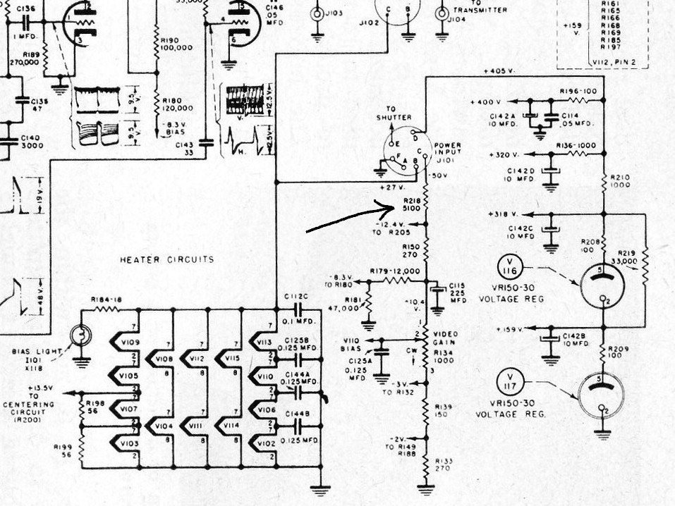
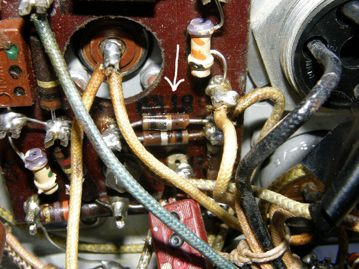
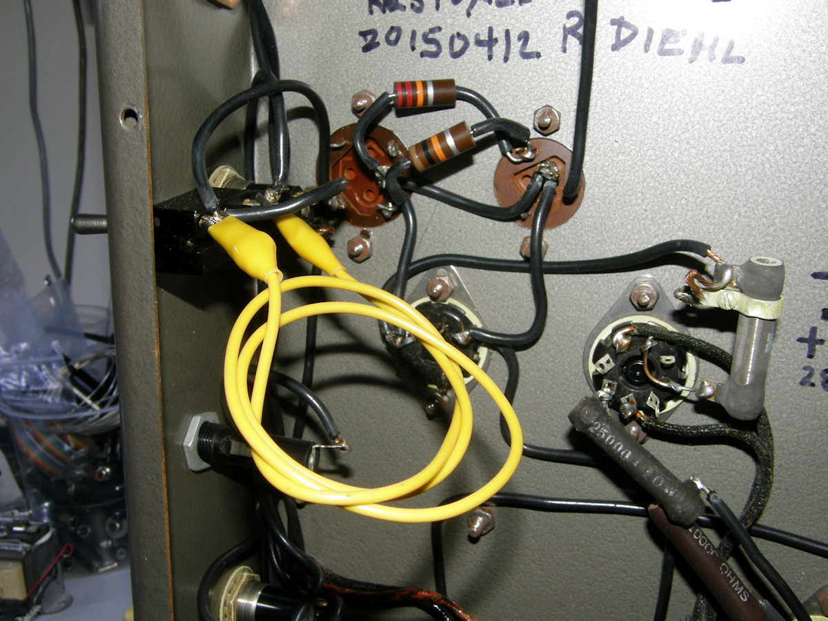
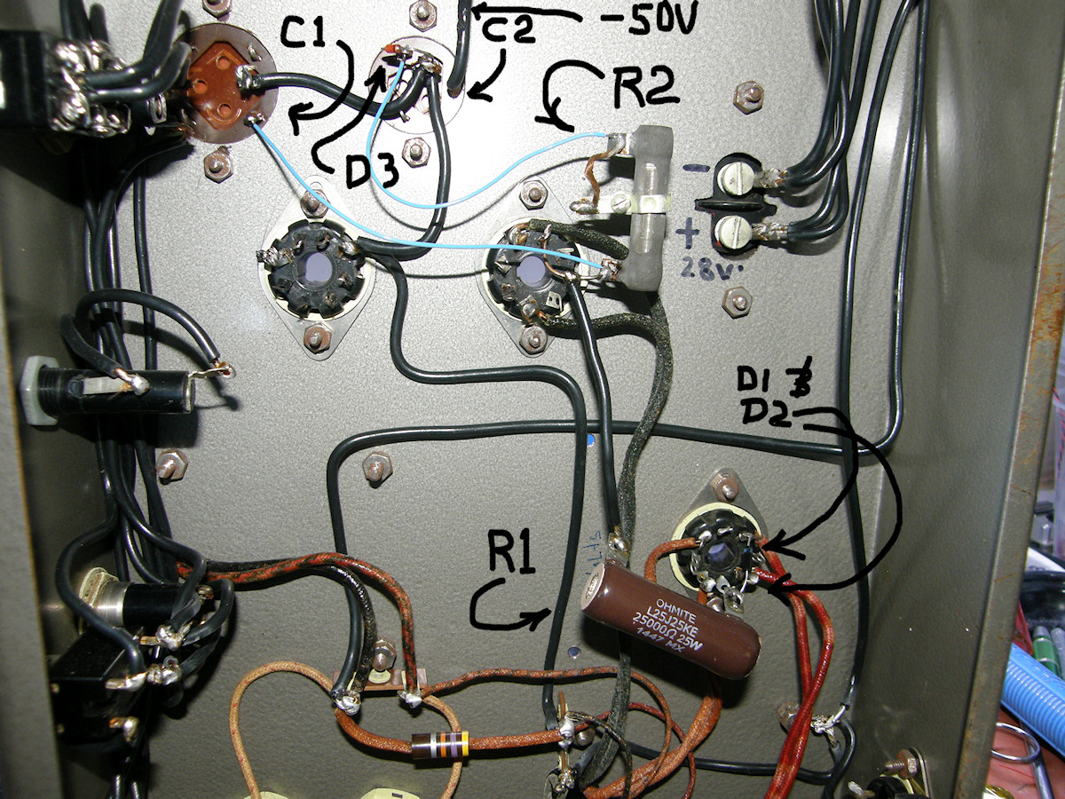
RIP R218. You will be missed. - 20150419 I spent a good part of today analyzing the -50 volt bias circuit. Shown in the first photo. The total resistance from pin C of J101 to ground was supposed to be 6,736 ohms. My magic ohm meter said it was 2.6K ohms instead. This is way too low. Upon inspection, it was discovered that the 5.1K resistor, R218, had been replaced by two 10K 1/2 watt resistors in parallel. This does indeed produce 5000 ohms. The two half watt resistors at R218 were well roasted and had changed value to 78 ohms. The other low value resistors in the chain are stressed as well. They are all reading greater than 25% high over their marked values. Even the pot R134, Video Gain, has changed value to 1.5K ohms. Will pick up replacement resistors for the entire bias circuit, tomorrow. Concerning the Video Gain pot, R134. It has changed value by 50%, going from 1K to 1.5K ohms. This will mess up the rest of the divider chain voltages. Since an identical replacement part is unlikely to turn up in the immediate future, I am going to correct the divider chain current by placing another resistor in parallel with R134 to restore the proper voltage drop. The wiper of the pot is looking into a load of a couple of megohms. So, we can treat that as being a floating contact or HiZ as it is called. The parallel resistor will not only restore the string current, it will produce the correct voltage drop across the pot. At one and a half K ohms, the pot now passes 4.93mA. This is 2.44mA low. So, a 7.4 volt drop at 2.44mA tells us we need to parallel a 3036 ohm (3K, 1%) resistor with the pot and all will be well. While I was at it, I disconnected and tested C115, rated 225uF @ 250V. Using my Extech 380193 digital LCR meter, the capacitor mesured 231uF with a capacitive reactance of .8 ohms @ 1KHz. So, as far as I can tell, C115 is perfectly good. This is how it goes. One small step at a time. 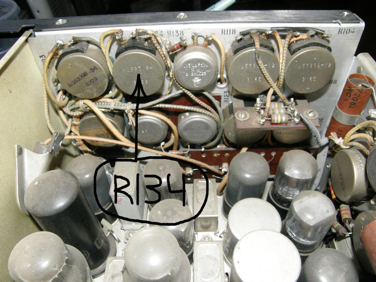
RIP R134. You will be replaced. - 20150422 Much to my surprise, I was able to locate a reasonable replacement for the Video Gain pot, R134. So, it will be replaced along with every resistor in the bias divider network. Also purchased a ship load of 50 volt zener diodes to replace the VR150 and voltage divider mess currently in the power supply. When that circuit failed, huge voltage was applied to the bias voltage divider chain, burning it to a crisp. This is the primary reason I loath shunt regulation. Not that the circuit is less efficient than a steam engine, burning ten times the power it sends to the load. Though that helps too. It's the fact that when, not if, the shunt regulator fails, the output voltage jumps to maximum voltage possible. In this case, 400 volts or more. I believe that's what happend here. It does, however, imply that the person I bought this from was possibly dishonest or, at the very least, misinformed. I would never have hooked up the supply if I had not been assured this was a recently working (in the past ten or twenty years) video camera. Apparently not. But, it's all good. Look how much we are learning! 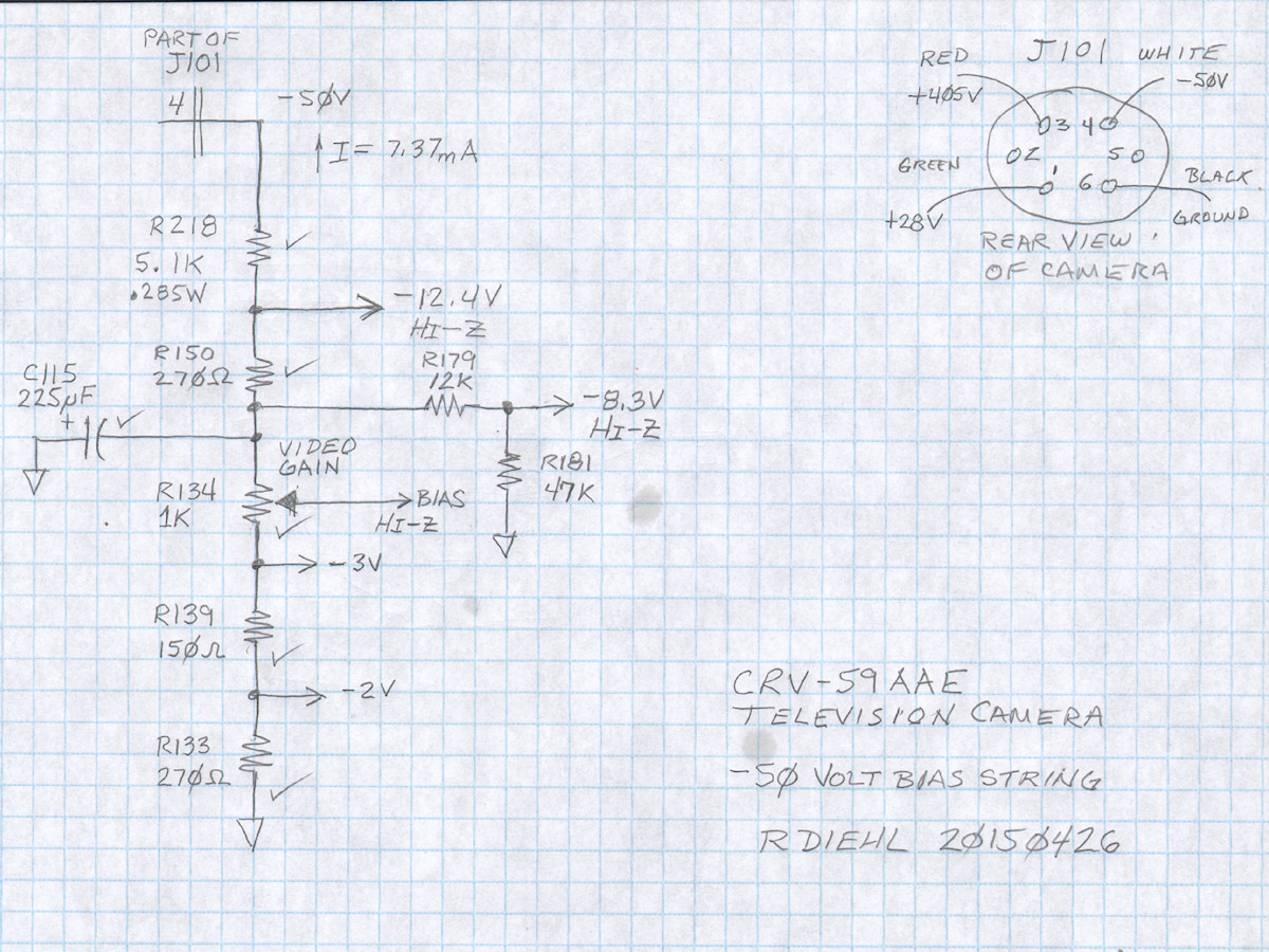
Congratulations R134. You will be retained! - 20150426 More surprises. Once I had unsoldered R134, the Video Gain pot, it measured almost exacly 1,000 ohms. In fact, it was 1,036 ohms. That's better than five percent accuracy. R134 gets to stay. R139 and R133 also tested within their 10% tolerances, so they too will not be changed immediatlely. I am curious to see how accurate the -3V and -2V bias voltages will be. R218 was completely replaced with two modern 11K, 1/2W resistors in parallel. R150 was also replaced with a modern half watt unit. R179 and R181 will be replaced as soon as I obtain them. They are both 25% or greater off value. No good. Gotta go! All four of these resistors were very burnt in appearance as well. 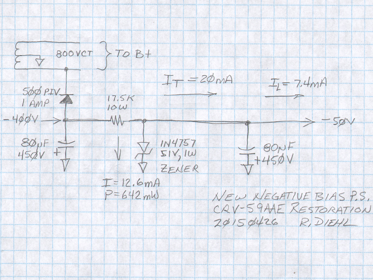
New negative bias power supply circuit - 20150426 Returning to the power supply. I have worked out the first order replacement for the original bias supply circuit. The old supply pulled about 25mA of current to create a regulated 150 volts. This then went through a two to one voltage divider to make the -50 volts. Cumbersome at best. My circuit also taps the 400 volt side of the main transformer, rectifiers it to produce -400 volts. (This is not dead accurate. But will be used of for this explaination) I calculated the series resistor by choosing a current of 20mA dropping from 400 volts to 50 volts. So, 350 volts divided by 20mA gives us 17.5K. The power is 350 volts times 20mA which comes out to seven watts. So, I specified a 17.5K ohm, 10 watt resistor. We already know the camera takes 7.4mA at -50 volts. This is "borrowed" from the 20mA flowing through the series resistor. The remaing 12.6mA is dropped by the zener diode and expended as 642 milliwatts of heat. Just over half a watt. Its clean and simple and can use many of the existing components in the circuit. I may keep the 6X5 recifier tube in place of the solid state diode. In the event that the camera is unplugged from the power supply when power is applied, the full 20mA of current will be passed through the zener diode. 50V at 20mA is 1 watt. So, the diode would be operating at its full power rating and would most likely fail in short order. So, I might try parallelling two zener diodess for more power handling capability or, better yet, put an AC power jumper in the octal plug so that the power supply can not be activated with the camera unplugged. The original schematic is short on cetain details. The power transformer is marked as 400 volts each side of the center tap to ground. Then his DC output is labeled 405 volts. Is the designer ignoring the rms to peak conversion of rectification? This means that the transformer is really outputting a lower AC voltage (Vrms / SQRT(2)) or 283Vrms. I will need to go in and measure these things next time I get the chance. If the -400 volts turns out to be 400 volts times the square root of two, or five hundred sixty six volts, then the dropping resistor changes to 25.8K, 20 watts. That's 566 volts minus 50 volts divided by 20mA. The power is caculated as 516 volts times 20mA which comes out to 10.3 watts. So, I chose a 20 watt resistor. Simple, no? 
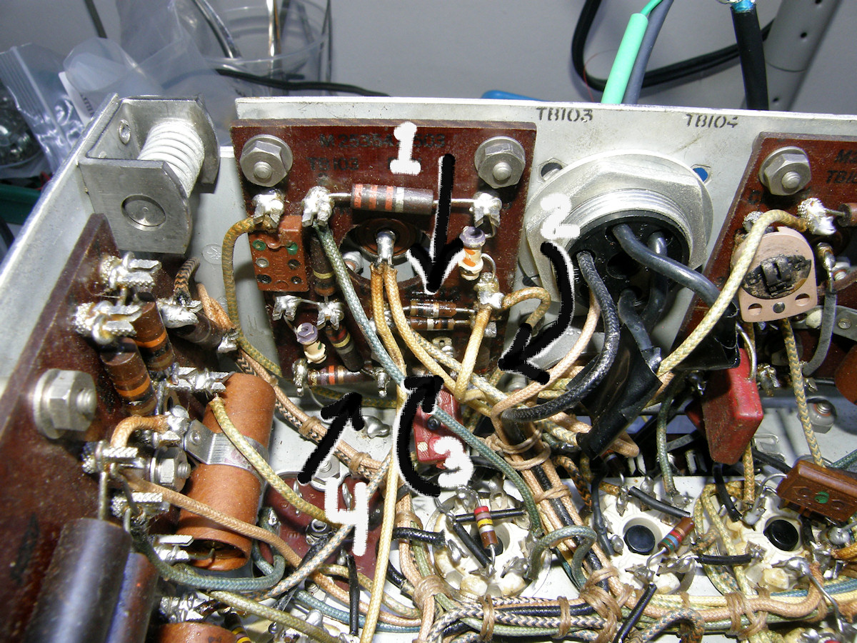
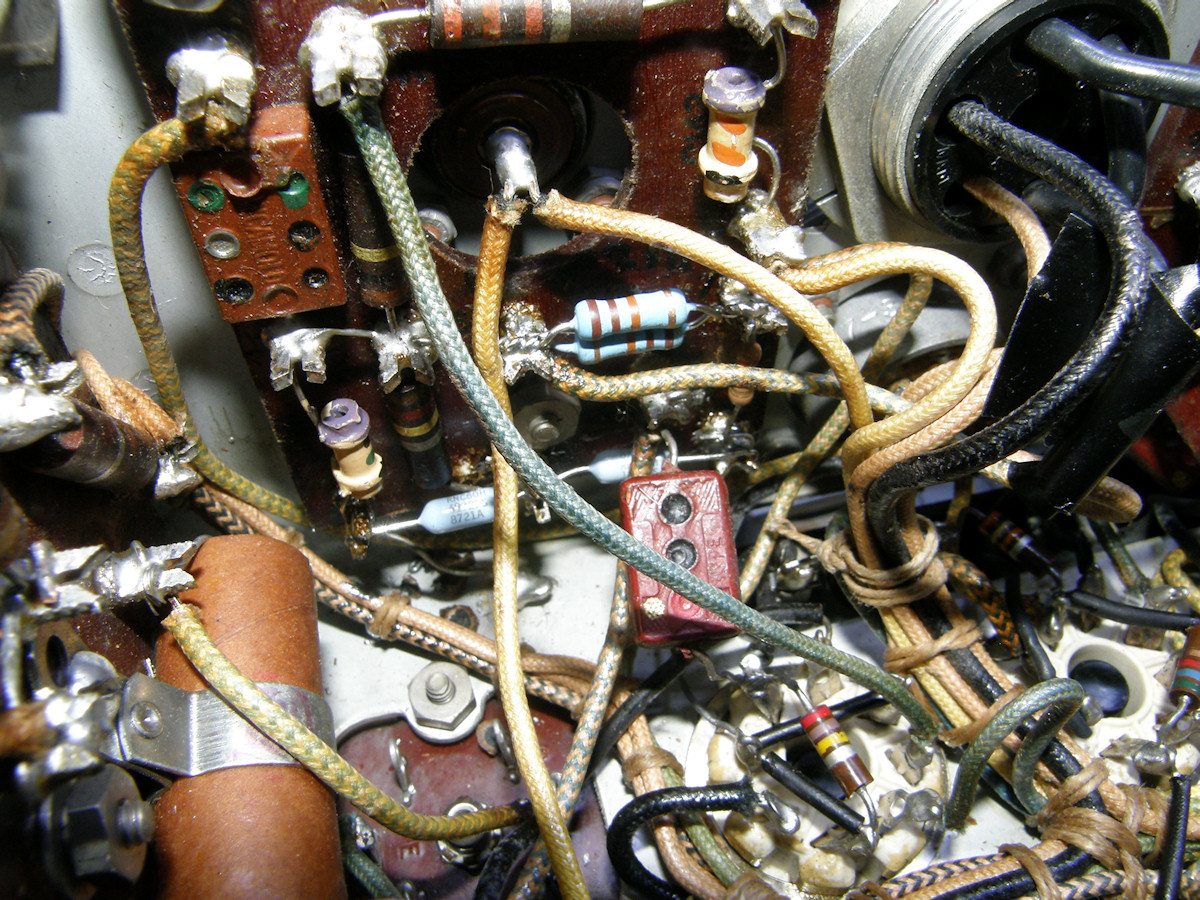
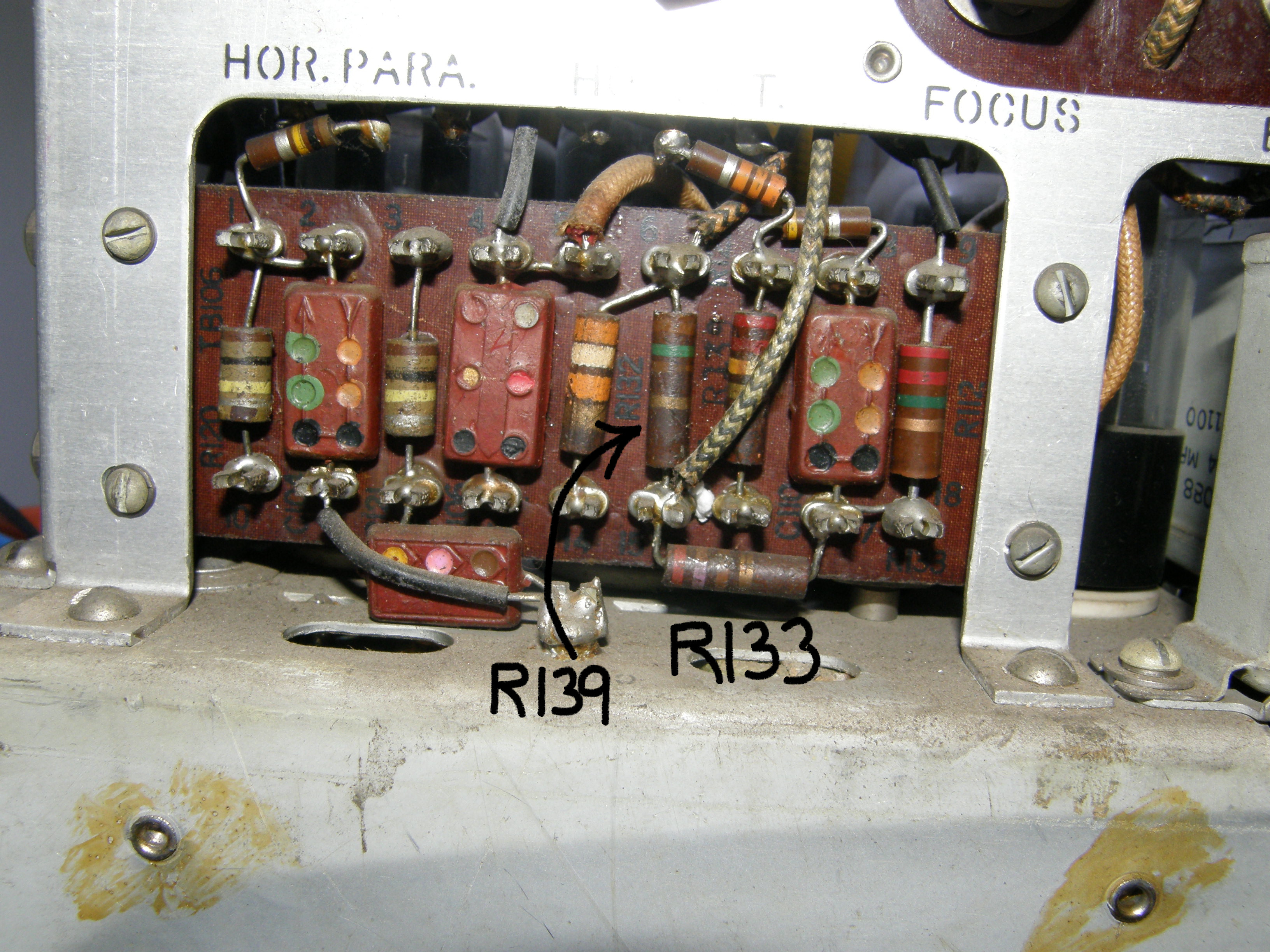
Alrighty then! - 20150427 In the photos above, we see the before and after shots of the resistor replacement. In total all seven suspect resistors were located and four of them were replaced. The total resistance now measured a little over 7K ohms which is very close to my calculated value of 6,790 ohms. Much better than the 2K ohms originally measured. It was challenging to locate the individual resistors within the camera as they can be located almost anywhere in the unit! At this point, this particular issue has been resolved. The four (most) burnt up resistors have been replaced. In photo number two I try to point out the resistors that will be replaced. In photo number three, you can see the new resistors in place. The 5.1K resistor, R218, is made of two 11K resistors in parallel which gives us 5.5K ohms, which is close enough. R150, R179 and R181 were replaced with modern half watt resistors. Last photo shows R139 and R133 that I did not need to replace immediately. R139, marked 150 ohms, measured 155 ohms and R181, marked 270 ohms, measured 275 ohms. That's good enough for now. 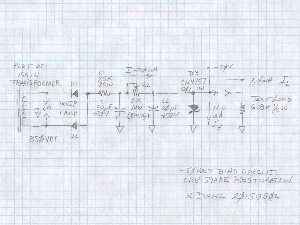
Second Order negative bias power supply circuit - 20150502 Back to the power supply. Received all of the components I ordered for this part of the project. If you refer back to the first order form of this circuit, you will see only one series rectifier diode in a half wave rectifier circuit. In the final analysis, my circuit failed for the same reason as the original design of this circuit. Insufficient recitfied voltage. There was not even enough to ionize the VR150 voltage regulator tube. That clue has been puzzling me for a while. I now have the answer. As I suspsected the first time I tried to run the camera, I had mismeasured the bias voltage. I thought I read 350 volts on the -50 volt output. It was not. Under load, the output could only muster 35 volts! My meter reads 35.0 which I misread as 350. Mystery solved there. But why was the output voltage so low? It has to do with half wave rectification. Even though we were providing a whopping 425 volts rms to the recifier, the final maximum output voltage was never more than 120V DC! [Here is an explanation as to why this is so]. 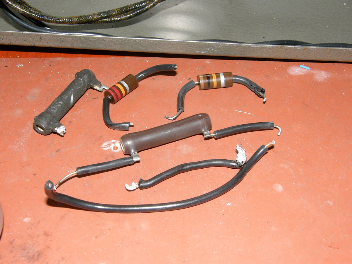
Old parts and the final output voltage under load. Success! - 20150502 Rearranging the circuit slightly and using both sides of the center tapped transformer solved the problem. My original calculations presumed full wave rectification, though I had forgottent this. Adding the second diode fixes that issue. We take advantage of the voltage divider formed by R1, R2 and D3. By the placement of R1, C1 never sees more than about 60 volts. With a working voltage of 450 volts, C1 and C2 are nicely over rated. If the zener diode ever failed however, both capacitors will explode. Youtube Videolabguy Channel: First Video from this Iconoscope camera - 20150503 We have reached the point where discernable images are visible on the monitor. The video is still grim as there are more defective components to ferret out. Bad as it is, it proves that the iconoscope tube can still make video. This is an improtant milestone. This also proves that my investment of time and money is not totally wasted. The main problem is excessive power supply hum on the B+ (+405VDC) power line. The ripple measured over two volts. I added additional capacitors in parallel with the existing capacitors in the B+ circuit and quality improved. But, I was only able to reduce the ripple voltage to .4 volts rms. Still far too high. The C- (-50V) bias has an rms AC voltage of less than 0.0001 volts. Looks like I will be shopping for big expensive capacitors soon. 
Hum greatly reduced in the image and the half inch video monitor- 20150503 The first photo has been taken after I made the previous video. After the fourth 10uF, 450V capacitor I tacked to the B+ line made no further improvement I checked the +28V supply for AC ripple. Found it too! Almost a full volt of ripple at 28 volts (3.57%). The 120Hz ripple was getting into the video and everything else through the tube heaters! Replaced the capacitor and you can see the results. Video is no longer modulated, sweep is no longer modulated, scan frequencies are no longer modulated. (as much) These are all awesome improvements! Now I need a larger monitor and much more light. Now where did I put my 300 watt light bar? My ten thousand dollar digital flat panel HDTV broadcast color TV monitor is not able to display the crude video signal coming from this camera. It refuses to unblank itself at all. If I can't see the image, I can't fix it. I need an analog CRT monitor. The only working analog CRT video monitor I could find in my junk pile was a tiny half inch viewfinder. But, it worked. With each test comes a new issue. With each issue comes a new test. With each lap around that track, things just get better and better. It can be quite slow going at times. Other times, a great burst of progress can occur in short order. Sometimes you must make do with what you have on hand. That's the nature of this hobby. Stop laughing at my video monitor! Well, folks. We have reached the first milestone. The camera is making recognizable pictures. There are still plenty of problems to troubleshoot and repair. This is a great point to end the first phase of the project and start the next phase. Besides this page has grown large enough. Time for the next chapter! Enjoy the [RCA RCV-59AAE Restoration Project], Part 2. REFERENCES: 1. Harjo Sales [CRV-59 television camera conversion] instructions. 2. Mr. Fisher's original [CRV-59AAE conversion notes] in no particular order. I received them shuffled. I was not the person who scanned this material either. It is what it is. But, it is rich in info if you take the time to study it. RELATED LINKS AND RESOURCES:
BIBLIOGRAPHY:
[HOME] [ELECTRONICS PROJECTS] [PART 2] [PART 3] Created: April 10, 2015 Last updated: June 7, 2015 |