LabGuy's World: Video Time Base
Correctors
New Addition! 02.07.28
197?: Ampex TBC-1 Direct Color or Heterodyne Color
TBC.
LabGuy, what exactly is a Time Base Corrector? I'm glad you asked!
A time base corrector
is a device that removes time variations from a video signal that is being
reproduced from a video tape recorder. This discussion will focus on direct
color video recorders, not be confused with heterodyne or color
under machines like Umatic or VHS. That is a different discussion.
Color under decks separate the color signal from the luma signal and record
them separately to the tape. In a direct color VTR, the entire video signal
modulates an FM carrier signal (like radio) which is recorded directly
to the tape.
Think of WOW and FLUTTER
in an audio tape recorder. This is a time distortion that is introduced
by speed variations as the tape passes through the transport. There are
many causes, all of them mechanical. A video tape recorder has all of these
time distortions and more. There is the same longitudinal wow and flutter
as in an audio recorder plus the mechanical vibrations and speed
variations of the rotary video head system. Tape stretch and wrinkles also
contribute to time base errors. The result of this is that the reproduced
video signal is constantly changing frequency and phase during playback.
Time base error can, and usually does, contain timing variations at several
different and unrelated frequencies. Each with its own causal factor.
If the video tape recorder
is referenced to an external sync generator, and the played back video
is compared against that reference, not so subtle time shifts can be easily
observed. On the video monitor, the picture may wobble back and forth,
the top of the picture may bend back and forth dramatically (called flag
waving) and just forget color playback at all! The variations are hundreds,
if not thousands of times greater than what the color demodulators in the
monitor can ever handle. When the VTR is referenced to a stable signal,
like station black reference, the time base averages out to zero over a
long period of time as the VTR minutely slows down and speeds up to stay
in time with the reference. However, at any given instant, the time error
can be many dozens of microseconds off depending on the mechanical stability
of the tape transport.
One solution to the problem
was developed initially for the Quadruplex format VTRs in the early 1960s.
An analog system, called AMTEC (AMpex Timing Error Compensator), was developed.
AMTEC consisted of a lumped delay line of series inductors and parallel
capacitors in the form of varactor diodes. A varactor diode is a special
device that, when reversed biased, behaves like a capacitor. Better yet,
its capacitance can be varied quite a bit by varying the applied voltage.
The time it takes a signal to pass through the delay line can be varied
and controlled very precisely by the applied control voltage. By passing
the playback signal through this delay line, and simultaneously varying
the control voltage in the opposite direction to the video's time base
error, a time restored signal is reproduced. It was possible now to correct
gross errors from the plus and minus ten microsecond range down to less
than plus or minus a quarter or even a tenth of a microsecond! This mechanism
worked well enough to allow the B/W VTRs to be mixed in with live video
for the first time. It was still not good enough for color.
A second variable delay,
with finer control, was inserted in the video path following the AMTEC
which finally brought the video signal back to its original tight spec
of less than plus or minus 2.5 nanoseconds. That is a total error range
of less than five billionths of a second stable! Quite an accomplishment
for the time period. This device was known as COLORTEC. RCA developed similar
solutions with their own unique, and trademarked, acronyms.
Now AMTEC and COLORTEC only worked
well because the playback from a quadruplex VTR is already stable to within
a couple of microseconds or two millionths of a second. This type of system
was not good |
enough for use with helical scan VTRs where
the time base error averaged between 10 and 150 microseconds or more. The
variable delay lines required would be so long, they would require their
own six foot equipment rack! Not to mention there would be no signal left
by the end of it either. The solution was to go digital! Convert the playback
video into ones and zeroes and store them in computer memory chips. Applying
digital methods to video made it possible to create any amount of delay
desired! (Or that could be afforded!)
The Digital Time Base
Corrector was invented by my good personal friend, Bill Hendershot, back
in about 1972 at his original company, Consolidated Video Systems (CVS,
Inc.) and for which he won an Emmy award. Bill's second company was called
ADDA, which stands for Analog to Digital / Digital to Analog. At that time,
digital memory was so expensive, a digital TBC with only one or two (video)
lines of memory was normal. It would be many years later when memories
became dense enough (and cheap enough) to store a field or even a frame
of video thus creating a new product called a frame synchronizer. (More
about those later...)
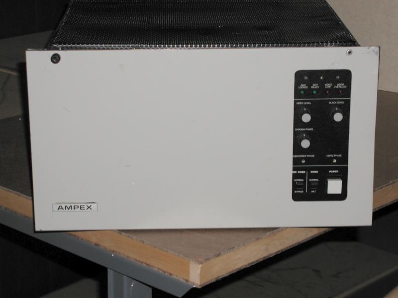
On to the Ampex TBC-1
shown in the photos above. This is the mate to the Ampex VPR-1 one inch
type A, and later type C, VTR. [See my VPR-1 here].
This is an all digital TBC with 12 lines of memory. That is way more than
enough for a VTR as stable as the VPR-1. The 12 line period is called the
Correction
Window. The TBC sends a signal called advanced sync to the VTR
in order to center it's timing in the middle of the correction window.
The VTR returns both off tape video and off tape RF (radio frequency) to
the TBC. The RF is used to sense drop outs, caused by tape defects and
momentary loss of head contact, and triggers the TBC to repeat the previous
line of good video which fills in the gap. Thus eliminating sparkles in
the playback video.
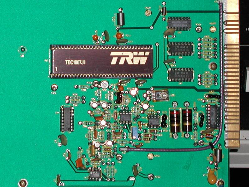
Before the off tape video
signal can be stored in the digital memories, it must be converted from
its normal analog form to a digital form. This is accomplished by a chip
called an Analog to Digital converter or A/D for short. The A/D chip used
in this TBC is shown in the third photo. It is the TRW TDC-1007J. This
is the first single chip converter to be introduced in the mid 1970s. It
is quite likely that this is a very late revision of this board. Earlier
versions of this converter board would have been packed solid with devices
and many complex and critical adjustments! A/D and D/A converter chips
evolved very rapidly at this point in history. We take them for granted
today, but the TDC-1007J was magic in its time! This chip samples
the video at over 14.3 million times per second, generating one byte for
each sample. These bytes are written into the memory chips.
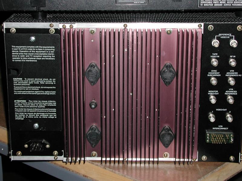
Going from left to right,
in the second photo, the boards contain the input timing generator which
locks to the jittering VTR video, the output timing generator which locks
to the station video reference, the A/D converter, three or more digital
memory boards, and finally a D/A (digital to analog converter) to give
us back the analog form of the video signal.
This black box made the
helical scan video recorder go from a sneered at piece of junk to the workhorses
of the industry! Prior to the introduction of the digital time base
corrector, only quadruplex VTRs were used for serious video production!
This TBC can be used
with either one inch Direct Color VTRs or with the more common Heterodyne
Color VTRS, like Umatics, Betas, and VHS as long as the VTR will accept
external sync reference. The TBC sends advanced sync to the VTR in order
to center its playback in the middle of the timing window. In the case
of heterodyne or "color under" VTRs, the TBC must first un-process
the color, then add it back to the luma prior to performing "proper" time
base correction.
WANTED: Nothing! I have
all manuals for this device. |
New Addition! 02.07.28
1978?: Ampex TBC-2B Direct Color or Heterodyne
Color TBC.
| This
TBC is essentially a later incarnation of the TBC-1. It contains exactly
the same functionality as its predecessor with (possibly) more video memory!
I am not sure how much. This information will be posted as soon as the
service manual for this beast arrives!
WANTED: Nothing! I have
all manuals for this device.
|
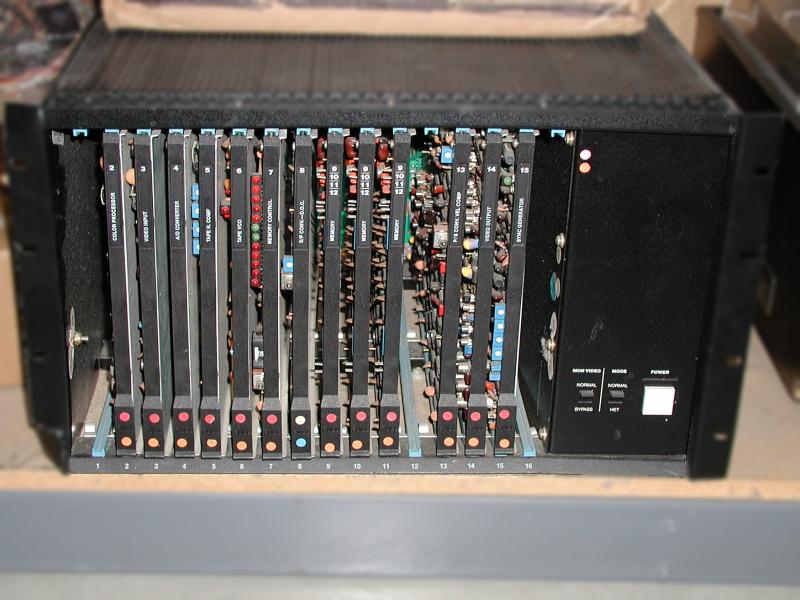
The TBC-2B contains 14 printed circuit boards. The chassis has 16 slots,
but not all are used or are for options. The boards, by slot number, have
the following functions assigned:
1 - Not used.
2 - Color Processor.
3 - Video Input.
4 - Analog to Digital Converter.
5 - Tape H. Comp.
6 - Tape VCO.
7 - Memory Control.
8 - Serial to Parallel Converter & Drop Out Compensator.
9 - Memory.
10 - Memory.
11 - Memory.
12 - Memory.
13 - Parallel to Serial Converter & Velocity Compensator.
14 - Video Output.
15 - Sync. Generator. |
New Addition! 02.07.30
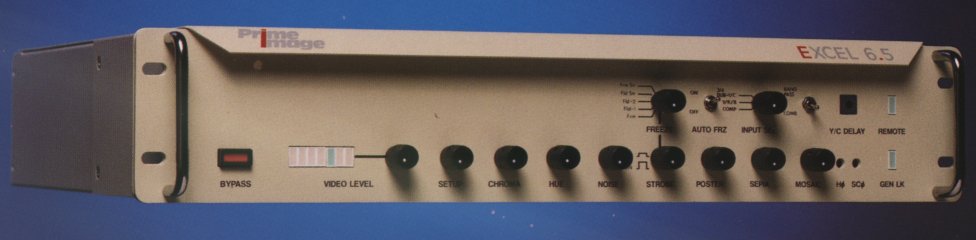
1991?: Prime
Image Excel 6.5 TBC / Synchronizer.
(The following text and the image above is from the advertising brochure
for this product. This item was generously donated by Steve Kyte.)
The Excel series is the
"ultimate" TBC line available, incorporating more high performance features
than any other time base corrector / synchronizer line on the market today.
This series is designed for high bandwidth operation at 6.5 Mhz while providing
a full 0-20 dB variable noise reduction in any operating mode, including
transcoding, with no impairment to high resolution characteristics.
Of particular significance
is the built in comb filter, which is front panel selectable. This feature
allows the operator to activate and / or deactivate the filter at any time,
even during an edit passage. In addition, all TBC and synchronizer functions
are fully accessible from the optional remote control unit.
The Excel 6.5 series
handles full transcoding of Y/C, 3/4 DUB, Y/R-Y/B-Y, and composite. All
units pass vertical interval test and reference signals without degradation.
Digital effects include: posterization, sepia, mosaic, strobe and freeze.
Six models are available
in this series: the model 600 TBC without digital effects; 601 TBC with
digital effects; 605 TBC composite only; 610 synchronizer with limited
digital effects; 611 synchronizer with full digital effects; and 650 synchronizer
composite only. Series options include the 60-R remote control unit, and
60-C high performance 3/4 dub cable. With prices ranging from $3,200.00
to $6,700.00, the Excel 6.5 series TBCs and Synchronizers offer the best
price / performance value in the industry. |
FEATURES:
-
More High Performance Functions than Any Other Line
-
6. 5 Mhz High bandwidth Operation
-
Full transcoding between Y/C, 3/4 DUB, Y/R-Y/B-Y, and Composite
-
0-20 dB Variable Noise Reduction
-
Front Panel Selectable Comb Filter
-
Built-In Digital Effects
-
Passes VITS and VIRS without Degradation
-
All Functions Available on Optional Remote Control Panel
-
Pricing to suit any budget
Of course, that was many
years ago. This TBC is no longer in production. That's why it's in this
museum. LabGuy's unit is not as pretty as the one in the photo. And it
does have the wrong cover on it. But, it is everything the description
says it is! Except for the Posterization, Sepia and Mosaic effects options.
WANTED: Nothing! I work
where all of the info and parts are available! |
Click here to:
Go
to: Extinct European Video Tape Recorders
Return
to the Exhibit Index
Return
to The Top of LabGuy's World
Last updated: December 09, 2002 |