|
LabGuy's World: Goldmark 1 - Theory of operation
PART FOUR: We are the joy boys of video! We push electrons to and fro! Only now we have to do this at a different rate. 144 Hz vertical and 29.16 Khz horizontal. This color television project consists of literally two separate projects. One side is the video processing and video monitor. The other is the color wheel and electronic servo system. Plus a half dozen support subsystems and this project becomes very intersting - very fast. 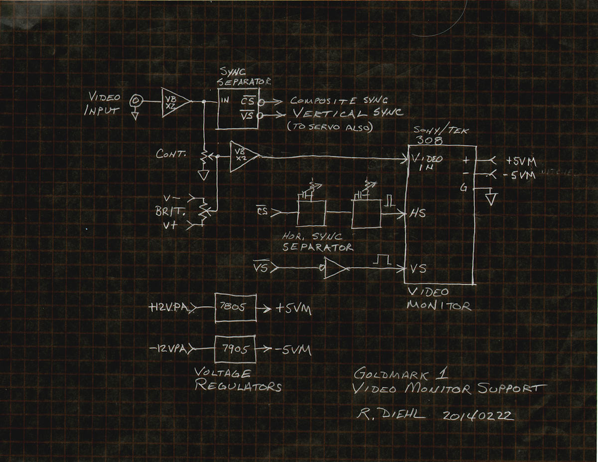
CRT video monitor and its support subsystems. Let's start with the video monitor and the support subsystem for the video monitor. The video monitor was salvaged from an obsolete Sony / Tektronix 308 logic analyzer. It requires a power supply of plus and minus five volts. I installed two five volt voltage regulators, on the servo board, just for this. In turn, the five volt regulators are supplied by the servo power amplifer plus and minus twelve volts which is only switched on if video is present. This is because the scan circuits on this video monitor are of the driven sweep variety and will do very bad things if powered up without sync pulses. So video detect with automatic power control is necessary to prevent damaging the video monitor. Referring to the diagram above. Video is buffered and sent to two places. The sync pulse separator and the video processing amplifier. The processing amplifier, or procamp, allows us to adjust both the amplitude and the DC offset of the video signal going to the monitor. The monitor requires blanking level at near zero volts and about 2.5 volts of drive. The two video buffer amplifiers (VB X2) have a combined maximimum gain of four. This is plenty of drive for this monitor. The two contorls correspond to the regular brightness and contrast controls on any television monitor. The next requirement is that the horizontal sync pulse be a coninuous single frequency. In this case, 29.16 KHz. The LM1881N sync separator IC that I used does not directly provide horizontal sync. It does provide composite sync (CS-) which certainly contains horizontal sync (HS-), but many other pulses as well. The additional pulses will cause disturbances in the flyback transformer and delection coils, distorting the image. To remove the extra pulse from CS-, it is passed through two timers. One is set to approximately 75% of the H scan time period. This blocks the 2H rate equalizer and serration pulses found only in the vertical interval. The next timer is adjusted manually until the monitor was behaving properly. The on time vs off time of the HS- to this monitor is very critical. So, I tweaked it in by eye for the brightest and geometrically best image. There was some back and forth tweaking required. Changing the timing of the sync has a profound effect on the flyback transformer and deflection coils.(Measurements on the timers to be provided soon.) The last requirement for the monitor is for a positive vertical sync pulse. The sync separator, of course, produces a negative pulse. A handy spare nand gate is used as an inverter to flip the pulse over and feed it to the monitor. All I had to do with vertical scan in the Sony monitor was adjust the vertical size control. This video monitor was a lot easier to convert to the 405 line, 144 field, 24 frame, six to one color interlace, video format, than my first attempt with the Akai VM-100 monitor. 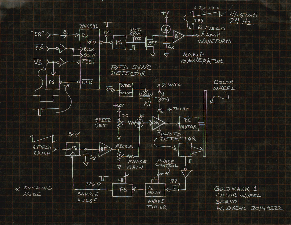
Color wheel servo subsystem. The servo subsystem is made of three important parts. First is the ramp generator. The second is the video presence detector. Last is the color wheel servo loop. The ramp voltage is locked to the first red sync pulse which occurs every six fields of video. This corresponds to one color frame. There are 24 color frames per second. I used a pulse counting process to find the red sync pulse. Vertical sync is used to load a preset value into an 8 bit counter which counts all of the rising edges in the composite sync during the period that VS- is high. In one field of video, there are normally 202 pulses in the counting period. Then vertical reloads the counter and it counts again. A field with a red sync pulse causes the counter to overflow and produces a carry pulse. Another timer, PS, shortens the overflow pulse to just enough to reset the ramp voltage to zero via the FET switch. The switch discharges capacitor CR while the pulse is high. The rest of the time, CR charges through constant current source KI. This produces a straight line ramp going from zero to five volts beginning in red field 1. The next important circuit is the video presence detector. It is a timer that will trigger on all incoming pulses. If the pulses are faster than its time out period, its output will stay high (or low) as ong as the pulses continue. This detected state turns on a double pole relay that now only sends power to the servo amplifer and the video monitor. This is necessary as there are no pulses if there is no video incoming. This could damage the monitor. The color wheel servo gets stupid if there is no video present because no ramp will be generated. The motor stalls and the amplifier roasts. Last is the closed loop servo for the DC motor. As the wheel spins an infrared detector senses a black bar passing under it once per rotation of the wheel. This produces a pulse which is fed to yet another timer. This is the wheel phase control. It can advance or retard the timing approximately plus and minus 170 degrees. The next timer shortens the pulse and sends it to trigger an analog switch. The ramp voltage is on the input of the sample and hold switch. The switch closes briefly and connects the ramp to a small capacitor which charges to the instantaneous voltage of the ramp. It stores this voltage on capacitor CS which is buffered by amplifier BF. The DC motor is driven by a high power DC amplifier. The input of the amlifier is the combination of a fixed voltage of about seven volts and the phase error voltage from the sample and hold. When the wheel is in lock, the sample pulse sits perfectly still at the middle of the ramp voltage. [HOME] [GOLDMARK 1, HOME] [GOLDMARK 1, CONSTRUCTION] Created: July 3, 2013, Last updated: February 25, 2014 |