|
LabGuy's World: Goldmark 1 - Construction of the set
PART FIVE: How did you put this all together, Labguy? The process is a form of controlled chaos - balanced by a dose of good luck. Plus my passion to honor Dr. Goldmark in my own small way. 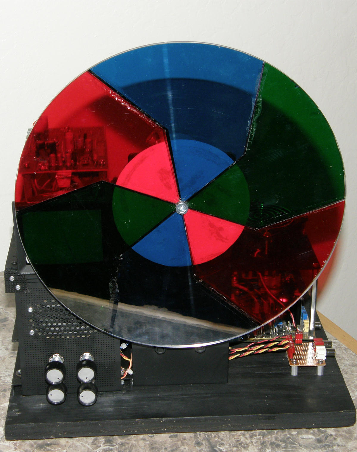


Let's take a walk around Goldmark 1 As of February 24, 2014, this is the completed state of the Goldmark 1 color video monitor. You might say this is Goldmark 1..., eh hem, ...Mark 1. I know. That hurts! The reason I tell you this, is because the motor and motor mount assembly are going to be replaced with better hardware in the near future. Here we see the Goldmark 1 in all its glory. In photo 1, we clearly see the six segment RBG color wheel. The conrols on the bottom left are for contrast, brightness, volume and wheel phase. Photo 2 reveals overall anatomy of the set. The small PCB, lower left, is the audio input and power distrubution board. It is responsible for routing 12 volts to the cooling fan and to the audio amplifier, as well as routing audio to and from the volume control. Photo 3 is a better look at my cooling assembly. Only two of the devices get very hot. With the new fan they are now no problem at all. Photo 4 reveals the two laptop computer power bricks that I used to power the set. Plus and minus 12 volts (regulated) at 3.3 amps max each. Only $8.50 a piece at the surplus store. Photo 5 shows how the supplies are suspended and mounted with a right angle bracket. We also see the side view of the little CRT monitor and the cabling. Beneath the monitor, the small brown PCB, is the audio amplifier. You will note that the entire unit uses many small connectors. This is because during construction, Goldmark 1 was assembled and disassembled dozens of times. The less soldering, the less damge. This completes the tour of the assemblies. 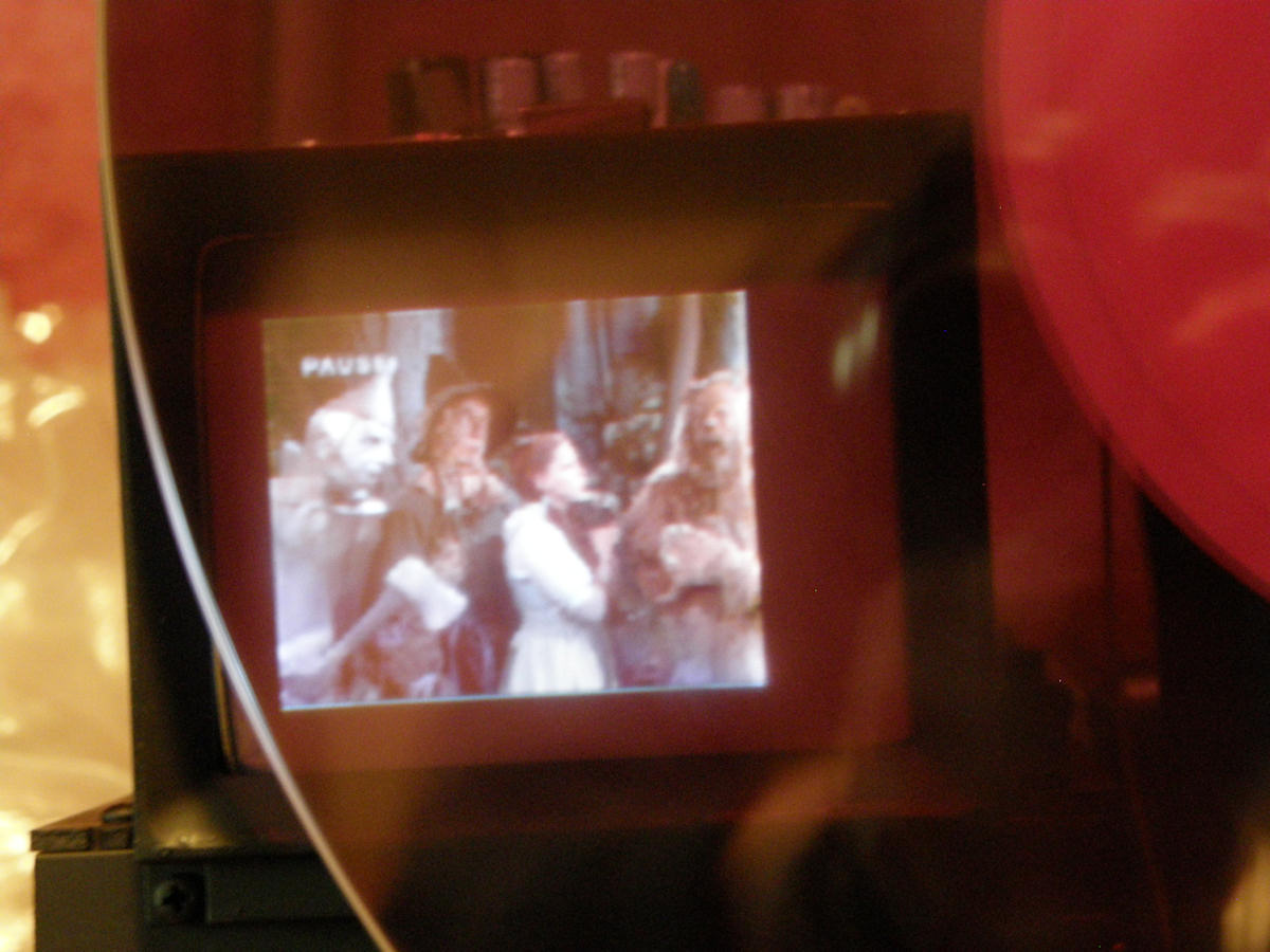
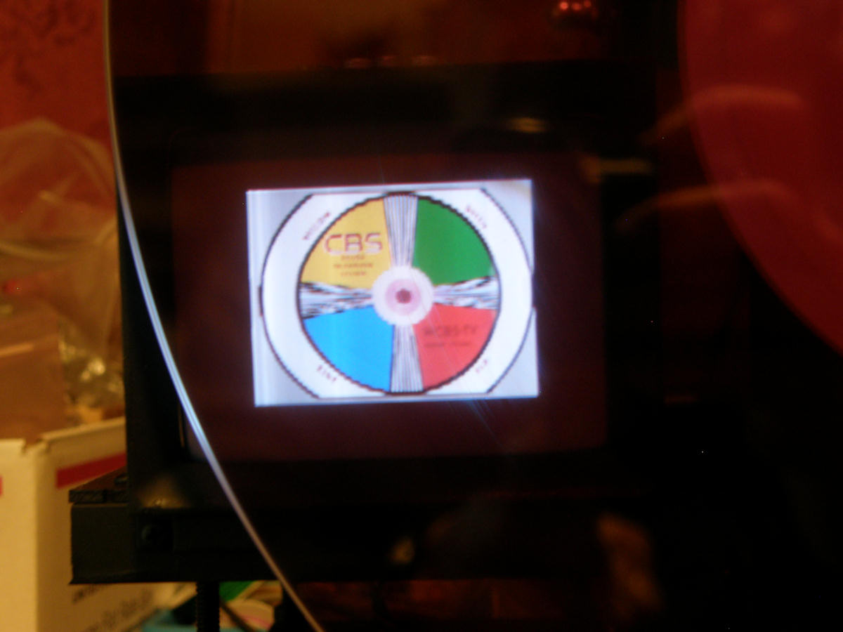

Goldmark 1 - Some of the first color screen shots (20140214) On February 14, 2014, I took these screen shots. In the first photo, the horizontal sync is not yet adjusted to optimum. In the next two photos, the scan size was optimized for brightest image that was in reasonable focus. Changing the scan rate changes the output voltage of the flyback power supply and, consequentially, the scan size. In turn, the CRT electron gun is biased incorrectly causing the image to blur or bloom. Next was to adjust the procamp controls, brightness and contrast to you regular folks, and got the greyscale virtually perfect. Future plans are to replace the motor and motor mounts and produce a perfectly balanced color wheel. In fact, an order was placed for brand new DC motor today. (20140224 - Thanks to Ralph Taggart,WB8DQT for this lead!) Two hundred and forty bucks. YIKES! But, it will improve the stabilty of the mechanism and eliminate all vibration. Stay tuned for that. Of course, that version of the TV will be known as Goldmark 1... Mark 2! (groan) See for yourself. I have posted two videos of the Goldmark 1 in operation, on youtube. Enjoy! [GOLDMARK 1 with servo and other issues, 4 minutes.] [GOLDMARK 1 operating very close to normal, 3 minutes.] I'd like to thank Cliff Benham for his guidance on this project. I'd like to also thank all the members of the Yahoo OLDVTRs discussion group who provided encouragement and great ideas. Be sure to check back occasionally. I will be making changes and updates to both the set and to this article. THE FOLLOWING TWO PAGES ARE RAW AND UNEDITED AT THIS TIME. THE INFORMATION IS RAMBLING AND HORRIDLY OUT OF DATE. YOU HAVE BEEN WARNED. [HOME] [ELECTRONICS PROJECTS] [GOLDMARK 1, TOP] [GOLDMARK 1, CIRCUIT DETAILS] Created: July 4, 2013, Last updated: February 25, 2014 |