|
LabGuy's World: - Part 1 1945 RCA PH-548/AXT-2A Image Orthicon Television Camera Restoration [HOME] [ELECTRONICS PROJECTS] [PART 2] 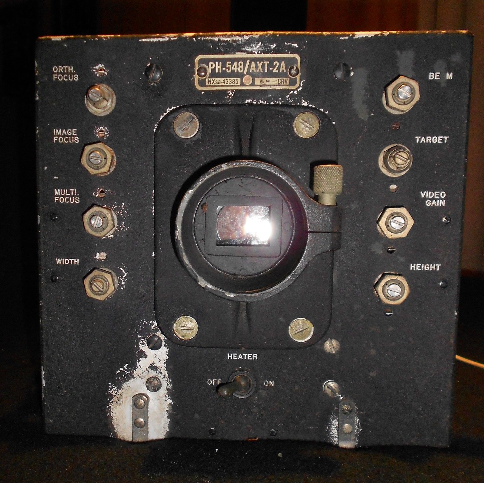
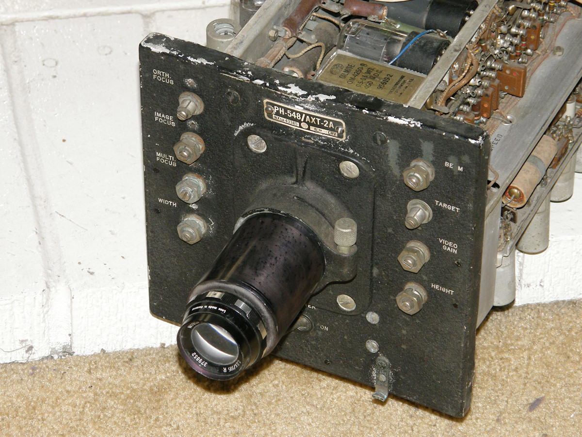
RCA PH548/AXT-2A Military Image Orthicon Camera - 20150813 Project goal: Get this $750 investment to fully operational status. This camera was produced by RCA in 1945. This will be my first image orthicon camera. 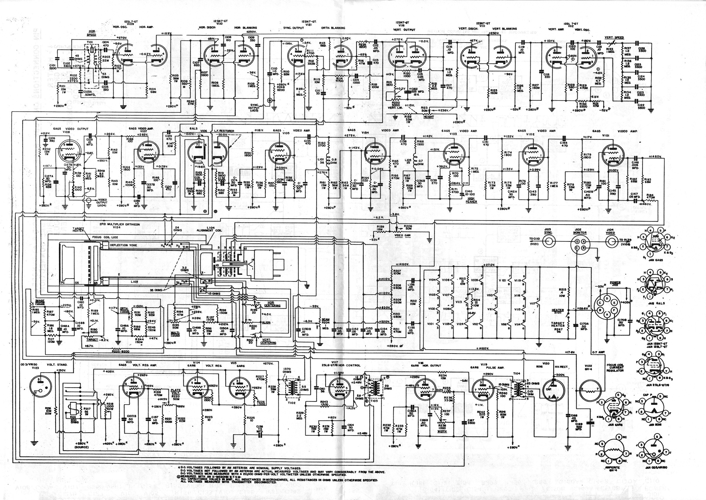
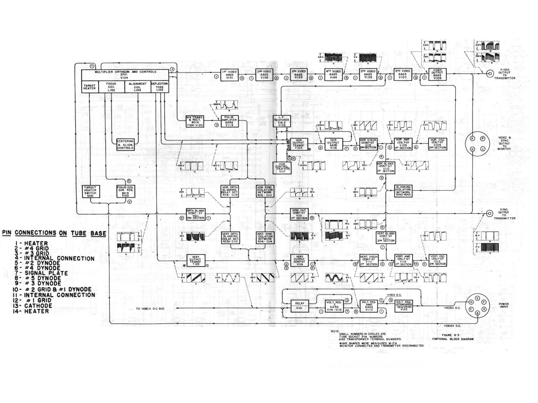
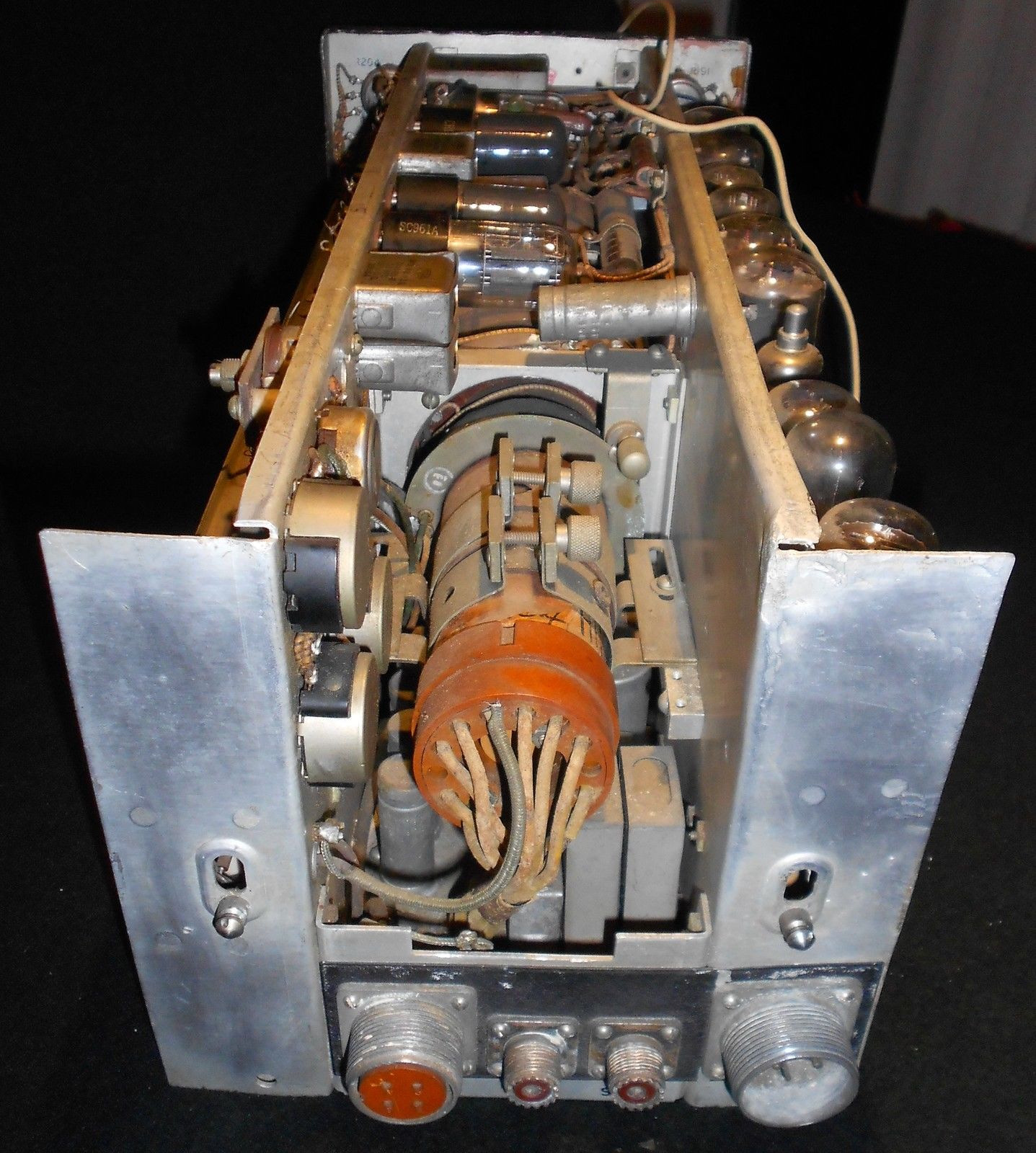
RCA PH548/AXT-2A Schematic and Block Diagrams - 20150815 The table radio of image orthicon television cameras. This is a design I would call 'simple as possible'. This camera lacks a complex sync generator. Scan is produced by two simple free running oscillators. Horizontal scan is about 14KHz and vertical scan is 40Hz. Those oscillators will be modified as necessary to produce 15.75KHz and 60Hz for 525/30 standard U.S. scan rate. Eventually, a proper sync generator will be added to update the camera to proper RS-170 standard operation. Of course, basic operation must be achieved first. Though the camera is fairly rough condition, I see no immediate show stoppers. The electronics are complete, there are no missing internal parts, with the exception of one easy to replace vacuum tube. The outer case is very banged up and will need 'body work'. The front panel is scuffed and scraped. I may eventually investigate getting the outer case and covers professionlly restored if my budget can support it. For the younger generation, the schematic diagram, shown above, was drawn by hand. With a pencil. On [vellum]!! (Look that up in your [Funk and Wagnalls]!) There were no fancy [CAD programs] in 1945! Nor a computer that could support it anyway. At the very best, the draftsman might have standardized 'rub on' stencils of common components. There were no Xerox copiers. Copies were made by photography studios or print shops, the actual walk in business kind, for several dollars a page! For every day and scratch work, they used a process called [blueprints], invented in 1861 by a French chemist. Blueprints were used since then until the arrival of true [Xerography]. RCA had entire buildings filled with drafting people and a printing shop on site before modern office automation as we know it today. Sharpen your number two pencils and put on your best starched white shirt if you want to work in the industry of 1945. Video: RCA 5820 Image Orthicon Tube, How it works (7:00) - 20150905 This camera uses a 2P21 image orthicon, the grandfather of the 5820. The 5820 will work in this camera too. I have two of them. One made by RCA and one made by Shibaden in Japan. As the video mentions, most image orthicons can be interchanged. One of the most complex vacuum tubes ever designed. You can see the spaghetti network of resistors and pots below the IO tube in the camera schematic. This is where all of the various DC control voltages for the tube's internal elements are set. This camera will be powered by the same supply I use for my RCA CRV-59AAE Iconoscope tube television camera. The PH548 is designed to interchange easily with the older camera. Other than a simple adapter plate, the PH-548 was plug and play with CRV-59AAE. Video: Incoming Inspection video, no audio (3:30) - 20150831 The image orthicon camera has finally arrived. I made a silent video that takes the viewer on a visual inspection of every inch of the camera. It will come in handy later when I start wondering about where does this and that go again? The image orthicon tube and yoke are buried deep within the middle of the unit and are hard to see at this time. We also see evidence of much hacking. Step one will be to remove, or back out, all of the modifications I can identify. This is not too dificult as the rework is glaring. Lamp cord is not suited for 1,400 volts circuits. . 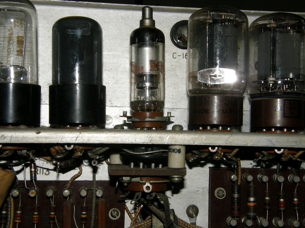
Substitute high voltage rectifier tube and adapter - 20150901 Let's get this ball rolling! Shall we? Let's start with the most obvious issue first. Someone was having trouble with the high voltage power supply. They made an adpater in order to substitute the original 8016 high voltage rectifer tube with a modern miniature version. I will replace this tube with the fully compatible and more common 1B3 or 1G3 high voltage rectifier tube, already purchased and in the mail as I write this. One down! You can safely bet that there will be plenty of more problems to deal with before we are done! I simply sat and stared at this rework for a while. It slowly became clear what is going on. Here's what happened: The sharp points the fellow left on the adapter will make little ion fountains with the high voltage on. Rule one in high voltage soldering - NO POINTS! I'll bet he was getting corona or arcs! That is why he switched to the external HV supply.... You can plainly see that the height of the points, when the adapter is in the socket, is right at the sides of the access hole in the chassis! Can you say, "Saint Elmo's fire?" The correct tube there will fix all of this. He did not know the substitute for the 8016 is the extremely common 1B3G and 1G3G high voltage rectifiers that were used in hundreds of models of TV sets. 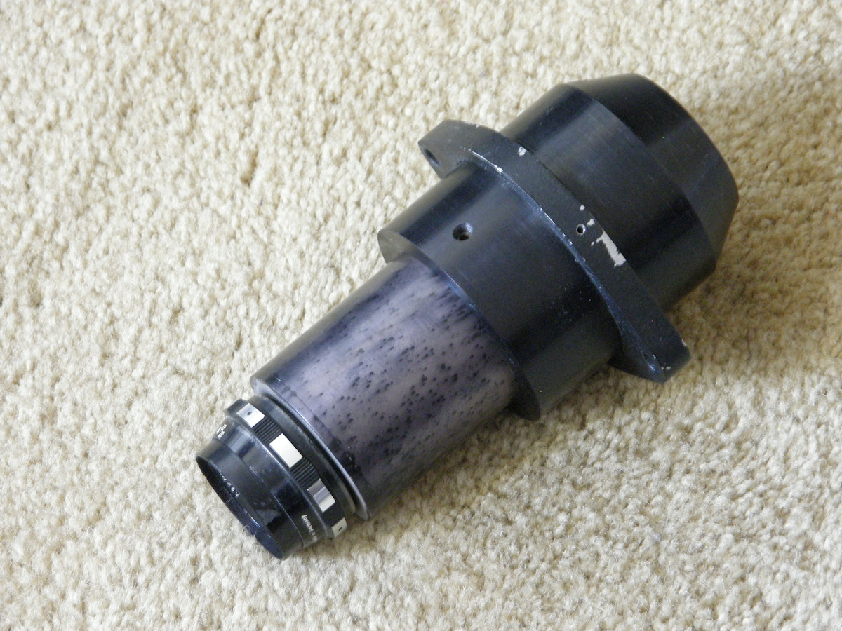
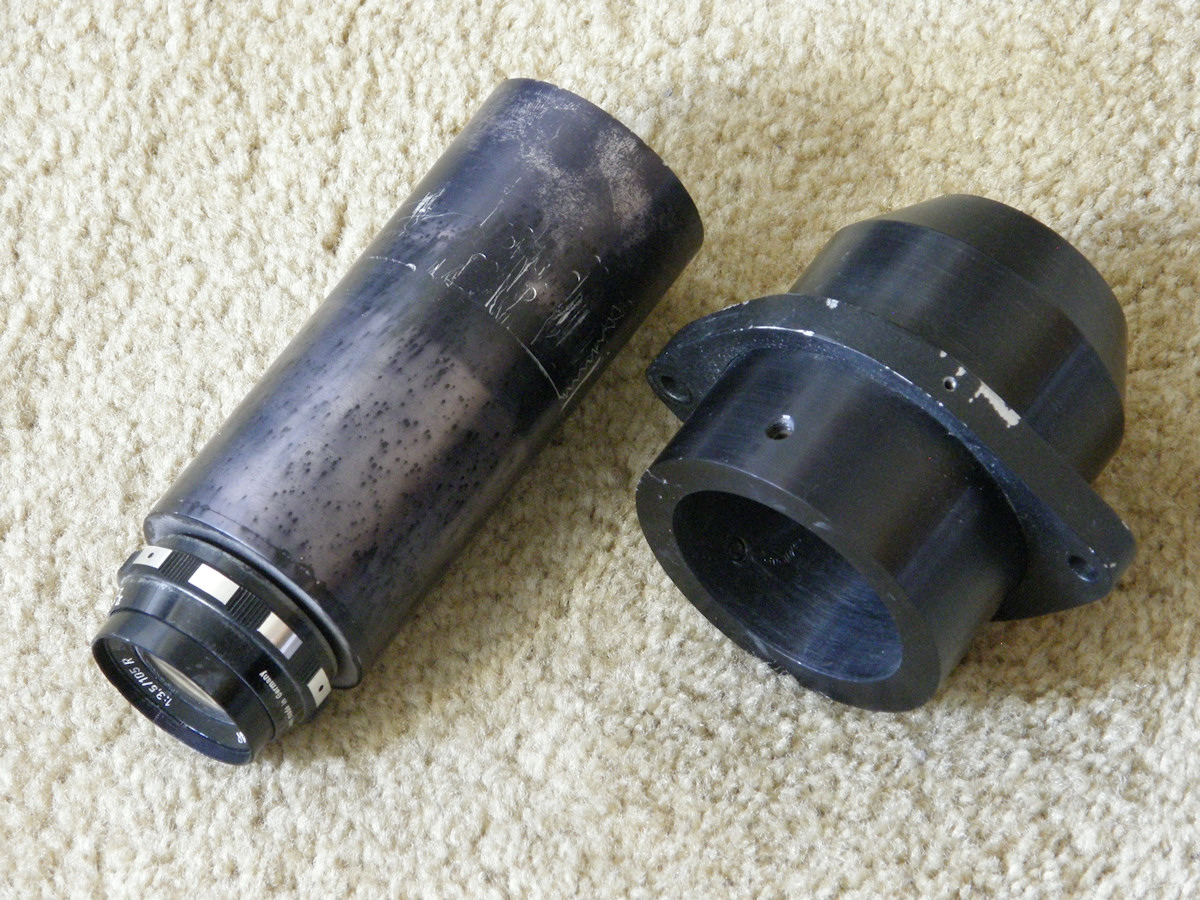
We found a lens! - 20150907 Went to the storage locker on a hunch today and got lucky! Thank you, David Crosthwait. David gave me an IVC-500 camera head that was once part of a film chain. It had this funky lens and adapter. An objective lens at the front, with an adjustable aperture. At the back end, a rather severe wide angle correcting lens. Perfect for a film chain. The front lens can be separated from the rear. Miracle of miracles! It fits the image orthicon camera lens mount perfectly! The objective lens is labeled with the following information. NOVOFLEX-NONFLEXAR, 1:3,5/105 R, S/N379852. Aperture range is f 3.5 to f 32. Focus testing with a sheet of paper shows that the focal plane for infinity is falling inside the back end of the adapter cylinder. It needs to focus about half an inch outside the back of this pipe. My crude measurement reveals that the objective lens is in infinite focus with a back distance of about 8cm. I will send the adapter out to the machinist to get it chopped down soon. Two down! Expecting the proper replacement 1B3GT rectifier tube - and a spare - in the mail tomorrow. Then we will be rid of that horridly inept adapter. 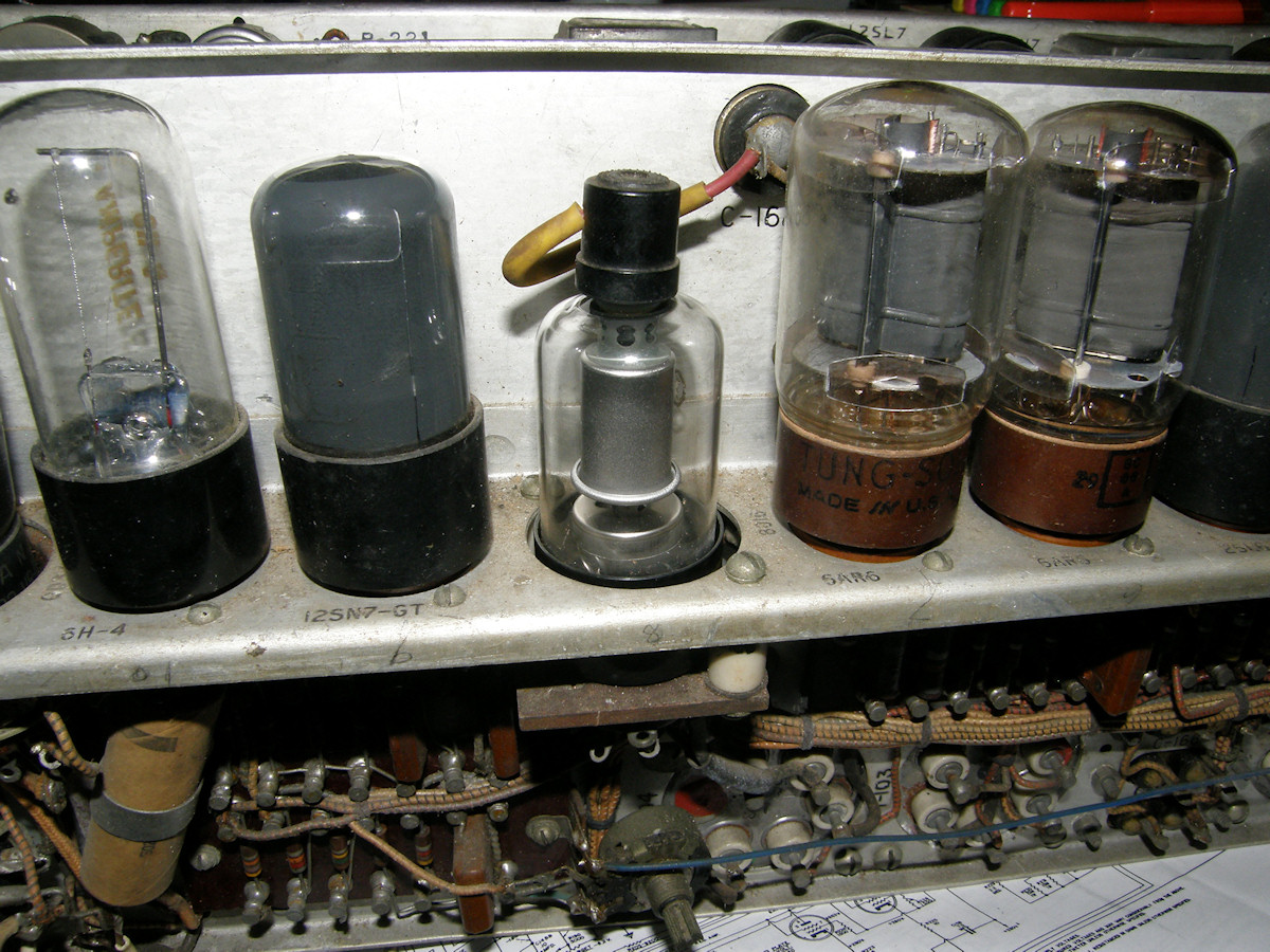
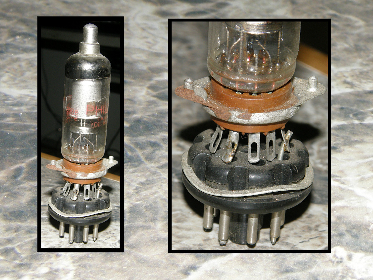
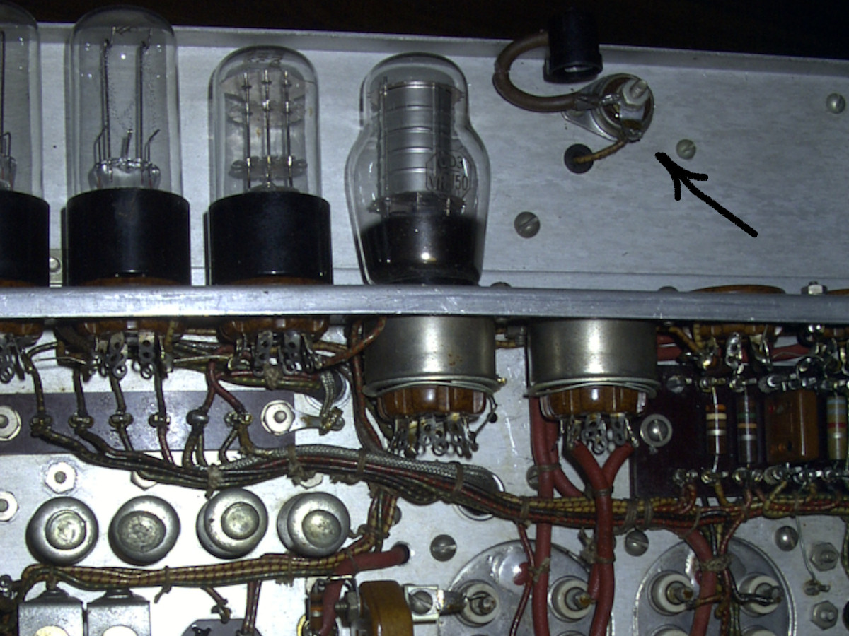
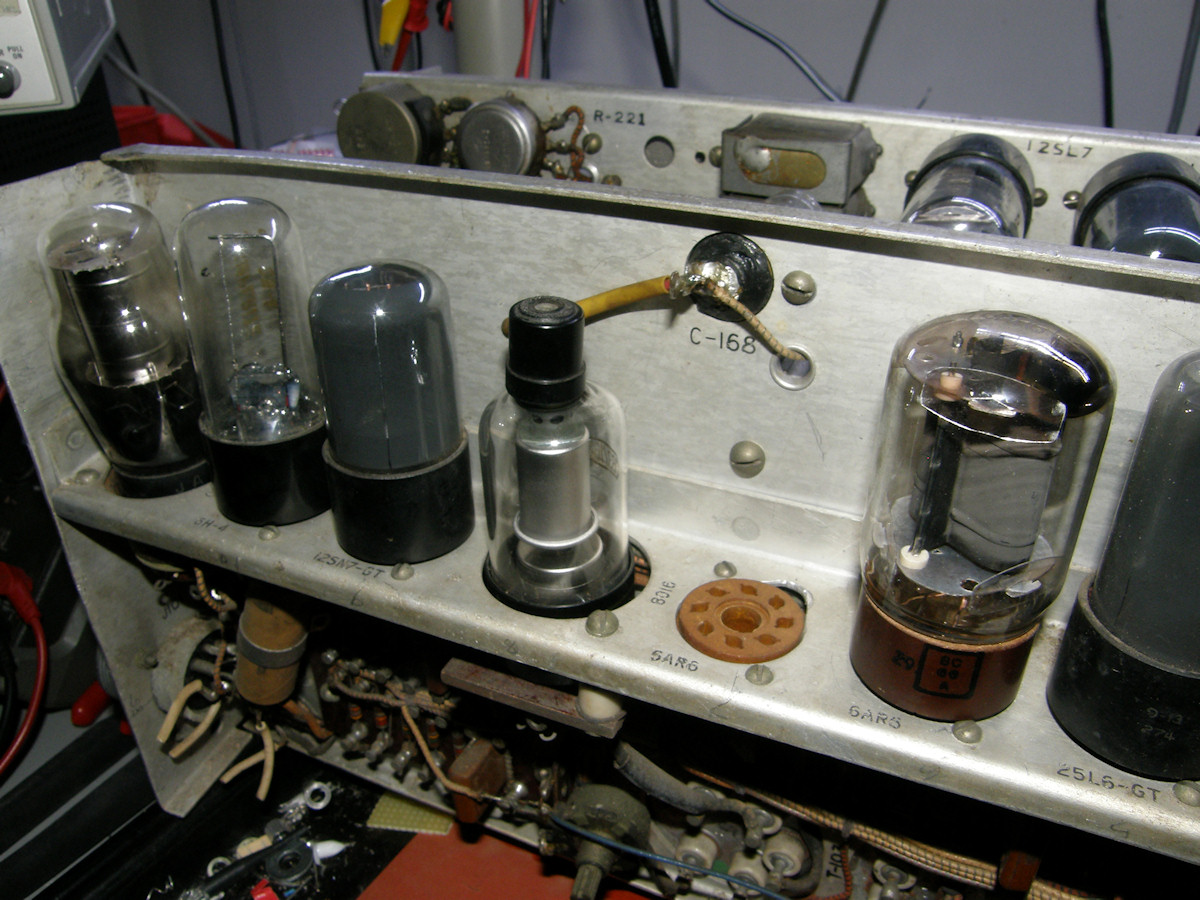
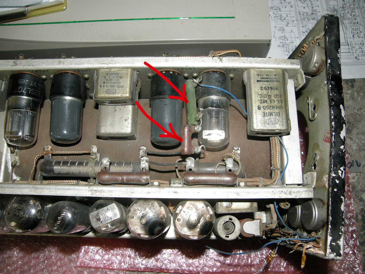
The replacement rectifier tube and some interesting past rework - 20150909 I'd like to thank Maurice Schechter for all of his invaluable assistance. I have been reading the Maintenance Handbook for this camera, which he so graciously provided. Lots of exploded views, with parts identification. It should be relatively easy to find that which I will be seeking. This camera is in rough shape and we are going to need all the help we can get for a successful restoration. First photo, center tube. I purchased two 1B3GT high voltage recifier tubes on Ebay as replacement for the 8016. Looking at the datasheets for these tubes, the 8016, 1B3 and 1G3 are relatively interchangable high voltage recifiers. I am more concerned about the capacitor (C168, .05uF, 1.6KV) that we can just see at the other end of the tube's cap wire. Maurice informs me this will most likely need to be rebuilt or replaced. This is fully expected and is why the previous enthusiast tried to use an external high voltage source. Worse than that, there are at least six more of them! As you can see, in the next two photos, there is the old rework to remove and undo. Once that is accomplished its off to a shop with a high pressure air hose to blow the dirt out. All tubes removed, including the 2P21 image orthicon. Of course! I found the procedure, in the manual, for removing and installing the image orthicon. I have more confidence with that information in hand. Also, Maurice has provided his own information for rebuilding the tubular high voltage capacitors in the power supply. More confidence! Watch the video! Video: Removing the image orthicon tube, no audio (3:30) - 20150911 The manual made the removal of the image orthicon very simple. This was the first time I saw this tube as well. It is not the original 2P21. It's an RCA 6474/1854. It has some smudged grease pencil notes on it that are hard to read. Though the word 'sticky' is easy to read. It looks well handled and grimy. It will clean up easily and will be our testing tube as it sounds like it has had better days. Some of the other notes and the serial number make me think this may be much later tube from the red channel of a color camera. 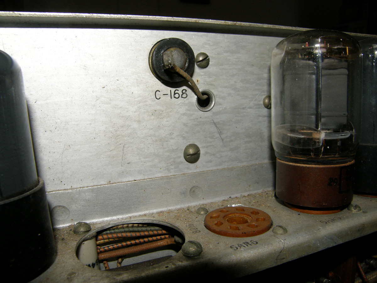
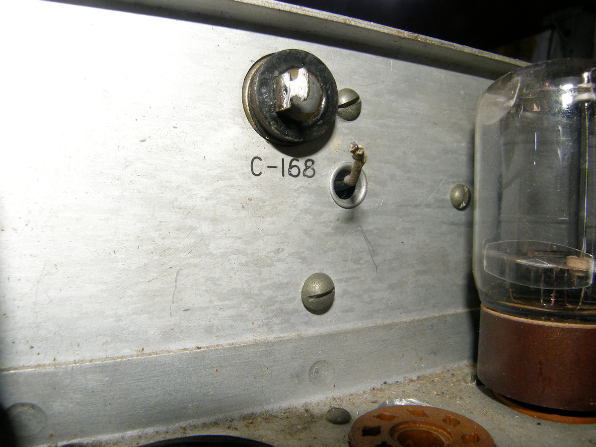
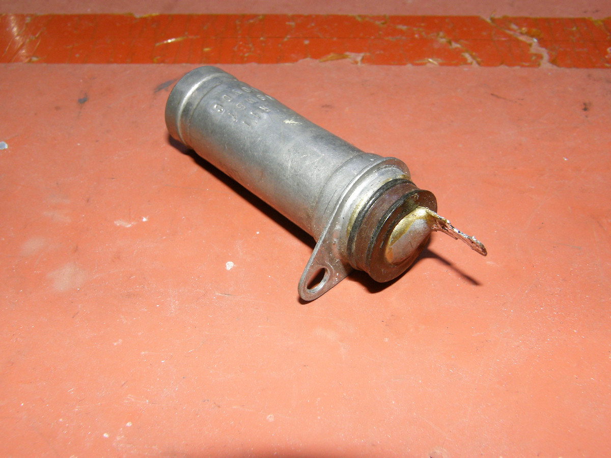
Removing the HV capacitor to prepare for replacement or refurbishing - 20150913 Capacitor, C-168, is rated at .05uF, 1600V. I have identified a replacement capacitor that may fit inside the body of the old capacitor. This will give us a more authentic appearing restoration. The old capacitor is opened and emptied. The modern capacitor is placed inside and its all sealed up again. 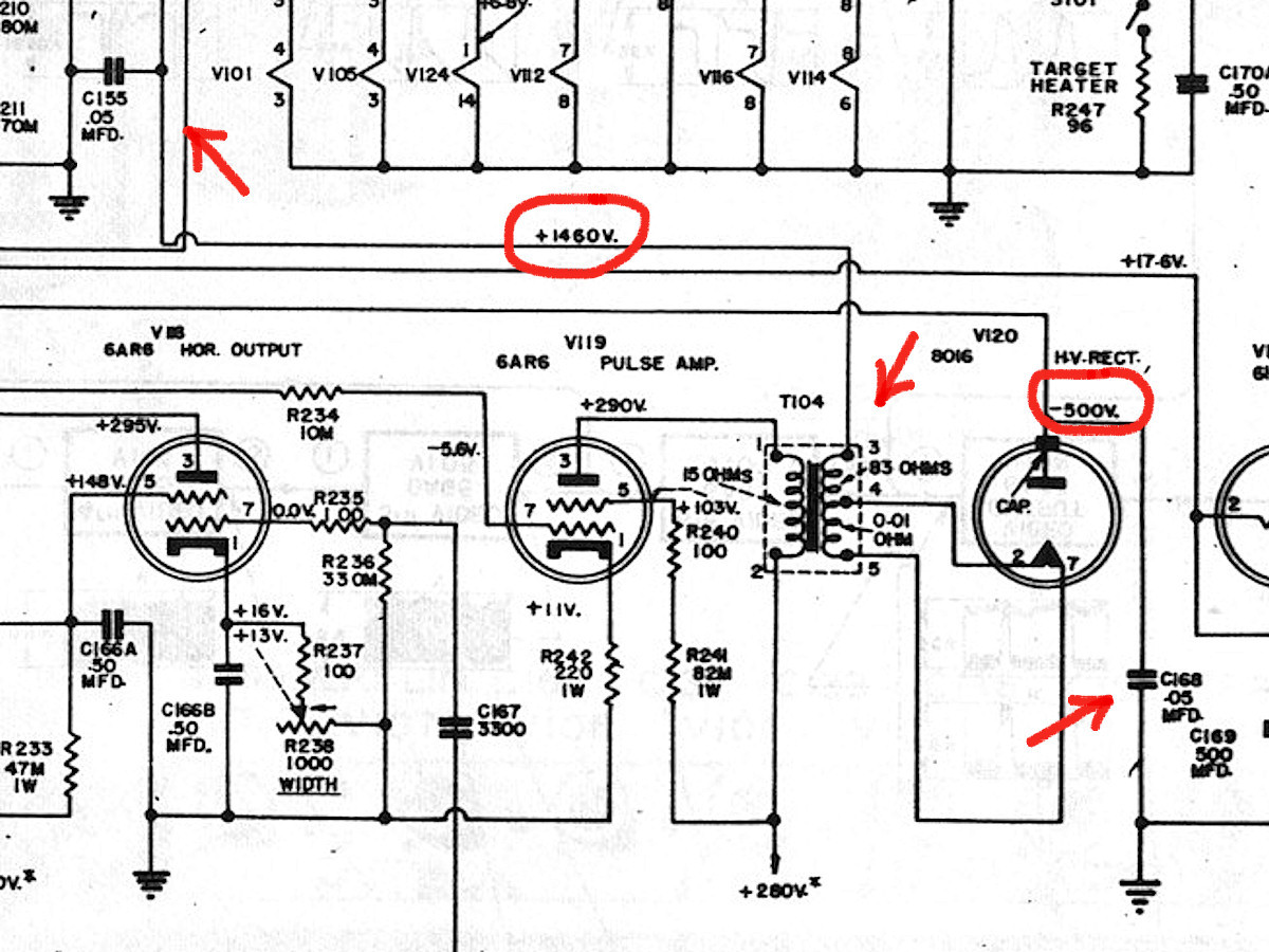
Looking at the schematic diagram, we see that C168 is the primary filter capacitor for the -500 volt source at the anode of the HV recitifer tube. The +1460V supply is derived at pin 3 of transformer T104. It's primary filter capacitor is C155, which is identical to C168. There are a total of at least seven of these capacitors in the camera. Most of them are in the dynode voltage divider circuit. If I have to replace one of them, then it would be prudent to replace all of them at that time. 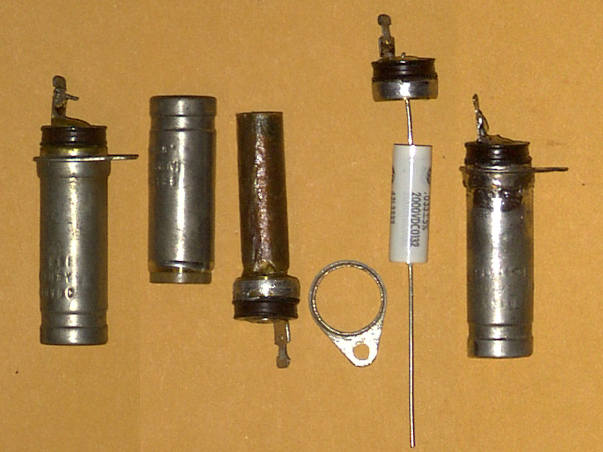
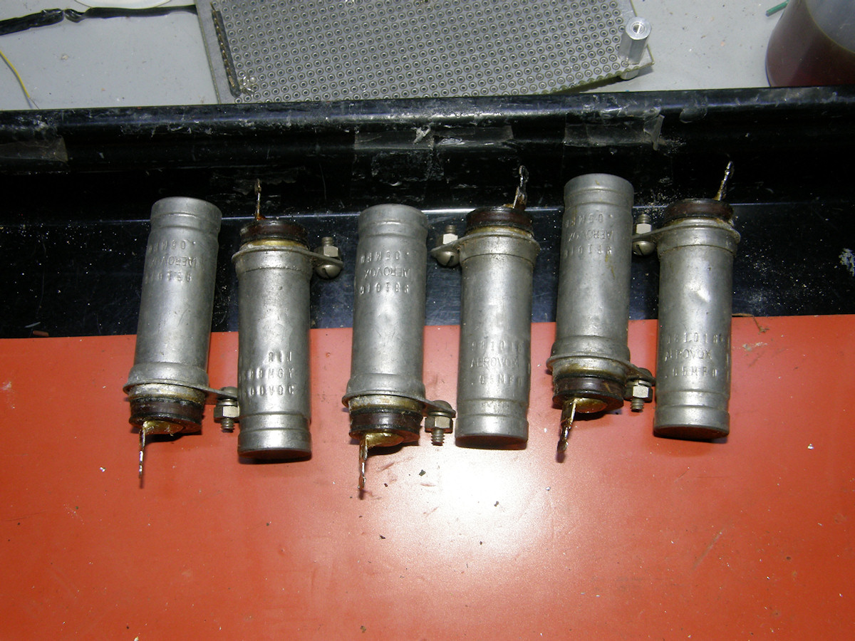
Here are two photos that Maurice Schechter shared with me. It is how he rebuilt the high voltage capacitors in his camera. I will follow this technique as well. I have located some suitable .047uF, 2KV tubular capacitors that should fit into metal body of the old part. We will find out when they arrive. 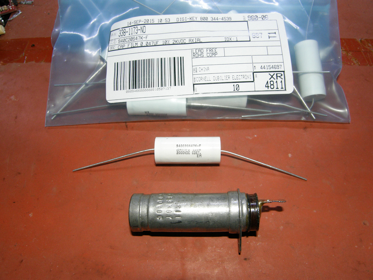
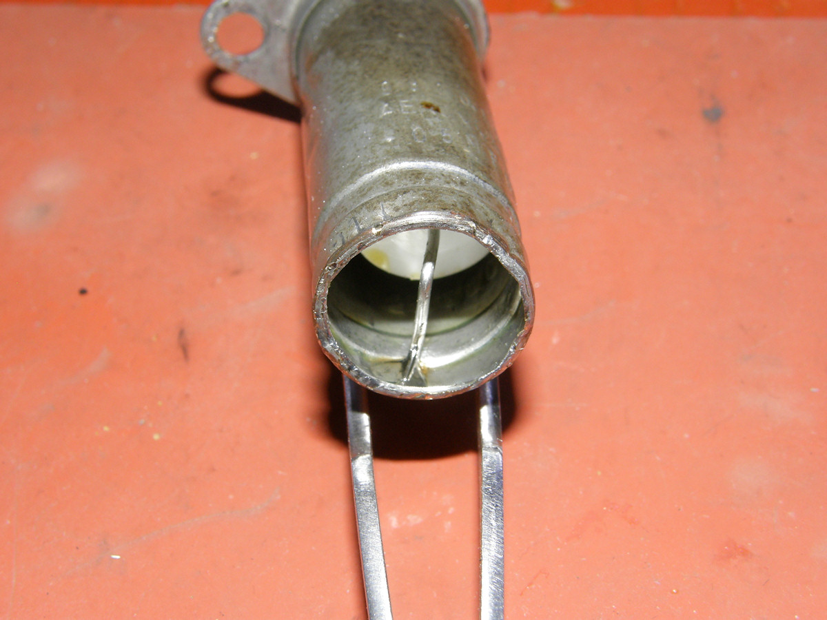
The replacement HV capacitor by Cornell Dubilier Electronics - 20150920 The original C168 is rated at .05uF, 2000 volts. Today, .05 is not a standardized unit. The closest standard unit is .047 and this will work just fine in this case. About $3.00 each. I obtained these units from [Digi-Key]. Cornell Dubilier Electronics part# 940C20S47K-F. Digi-Key [part# 338-1173-ND]. The old capacitor has an outside diameter of 685 mils / 0.685 inches. The new capacitor has an outside diameter of 530 mils. The old capacitor has a uasable length of 1.65 inches while the new one is only 1.26 inches long. There will be no issue at all with making the new part fit within the old one. The rebuilt part will be superior to the original. The outer case of the old part is tin plated brass. In many ways, it is manufactured exactly the same as firearms ammunition. A cylindrical can is pressed from a disc shaped metal blank in a series of presses. I have to wonder if the machines that made these capacitors in the 1940s were originally used for that very purpose. It was world war two afterall. Of course the actual metal working craft predates that period by many centuries! Later that day...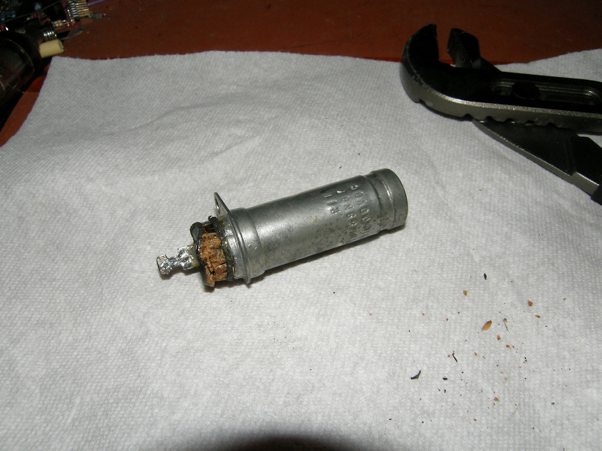
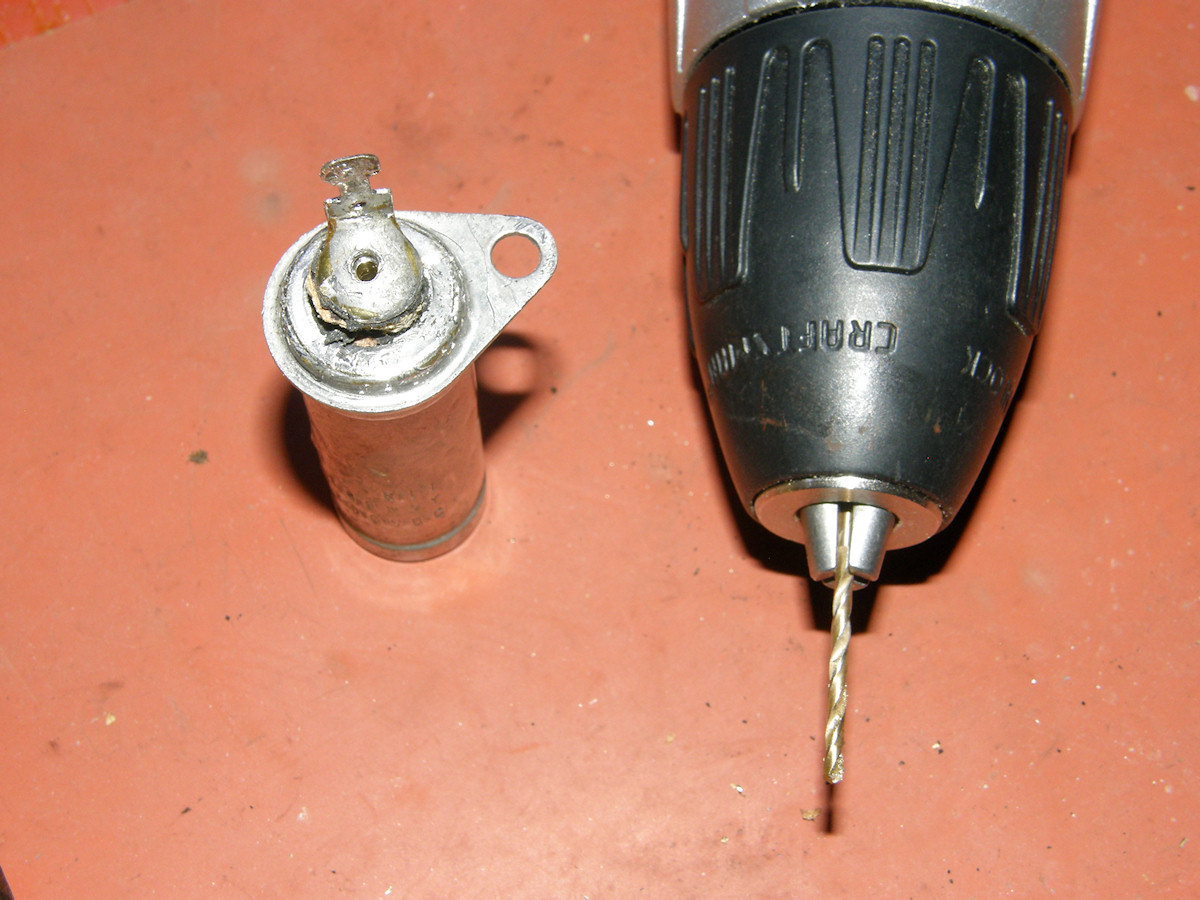
Climbing the learning curve - 20150920 My original assumption about the end insulator being made of bakelite was incorrect. It was some form of compressed composite fiber and resin material. I tried to gently pry it out of the can and failed. The material began to crumble with only the slightest pressure. Hrummph! (Her what?) Fine. Let's dig it all out and figure out how to rebuild it later. Nope. The spacer was molded to the can which had a rather wide shoulder beneath the fiber washer. A closer look at the opposite end of the can (not shown), showed that it was sealed with solder! The old plug and solder method, hmmmm? A flat brass disc is placed in the end of the can and flooded over with solder. A small hole passed the lead from the capacitor within. We can take that out with a propane torch. Assuming, to be safe, this capacitor was filled with oil and could burst violently when heated, I drilled a relief hole through the top. Going to need this later anyway to pass the lead of the replacement capacitor. 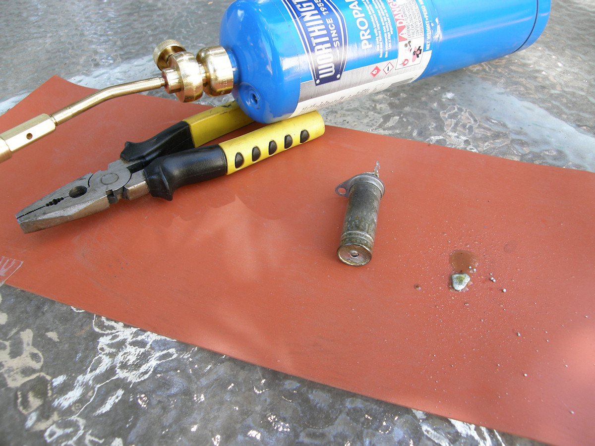
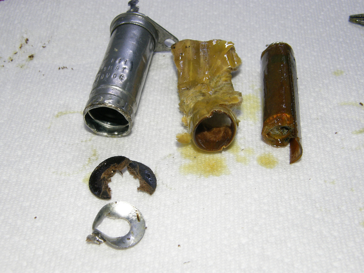
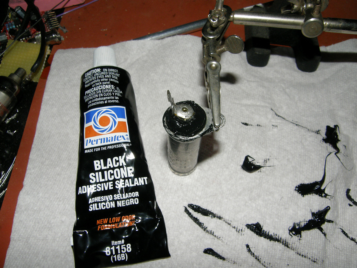
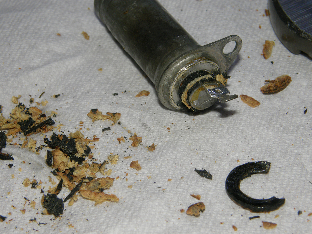
Finally. Understanding achieved - 20150920 Using a torch, I melted the solder out of the bottom of the capacitor can. Got a blast of oil from both ends of the can with the heat applied. Probably some nasty stuff! Drilled a quarter inch hole in the end disk and pried it out wih a screwdriver. Another fiber washer came with it. There was also a fiber liner as well as the remains of the actual capacitor. All oil soaked. Eeeewwwww! This can is cosmetically damaged beyond repair. I will reinstall it where it won't be seen. There are seven more of these capacitors to rebuild yet! We won't be breaking any more of the fiber washers on the top end. Fixed this one with some handy black silicone rubber. Will resume rebuild in 24 hours to allow the silicone to set up solid. Even later that same day...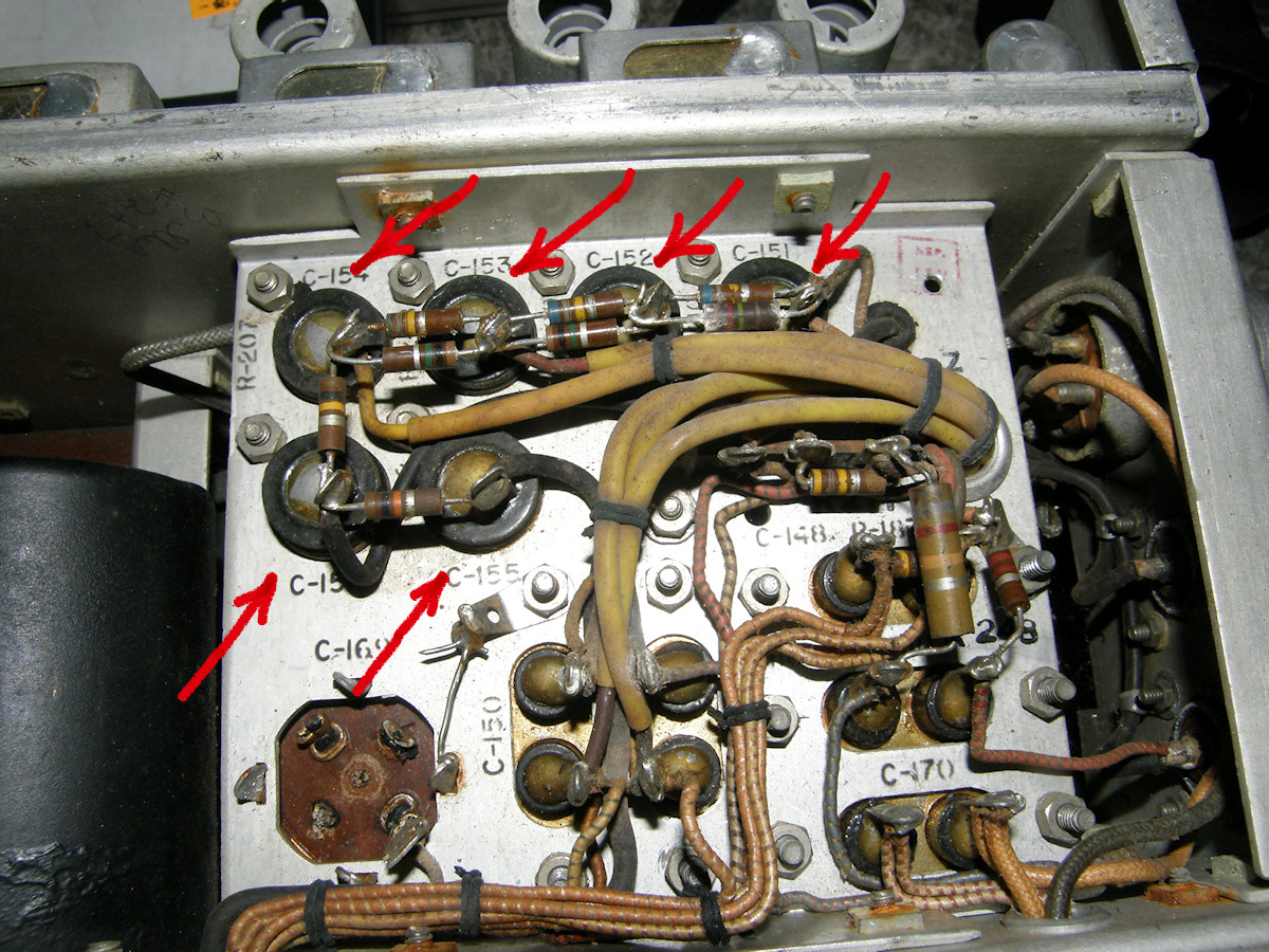
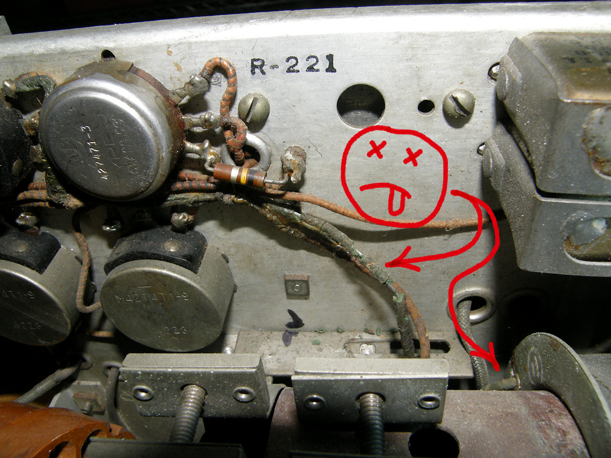
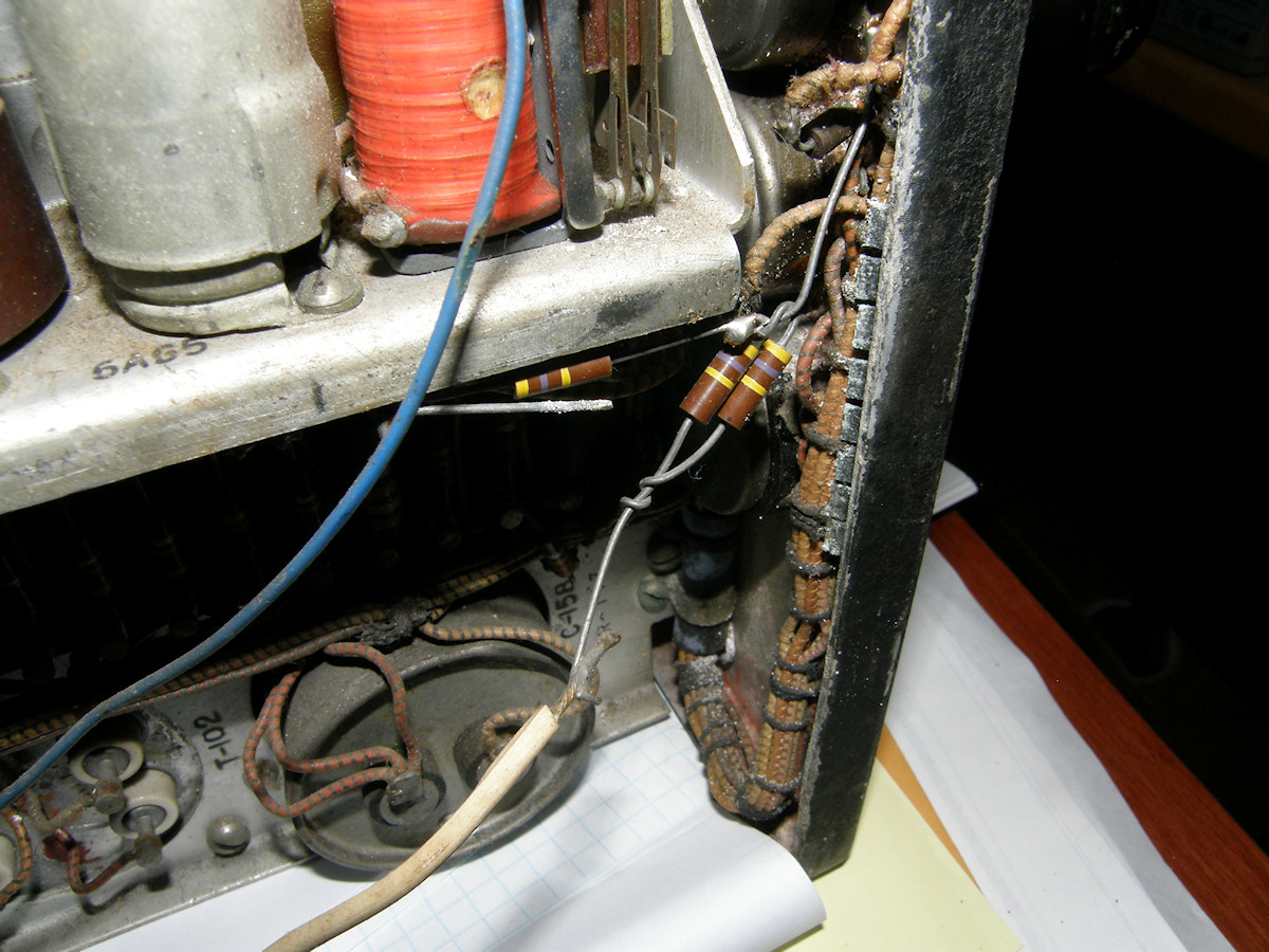
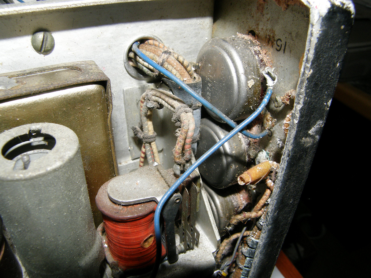
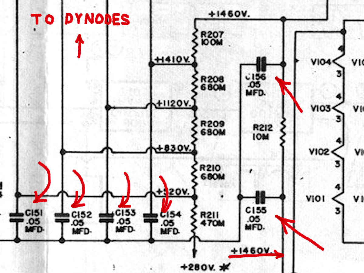
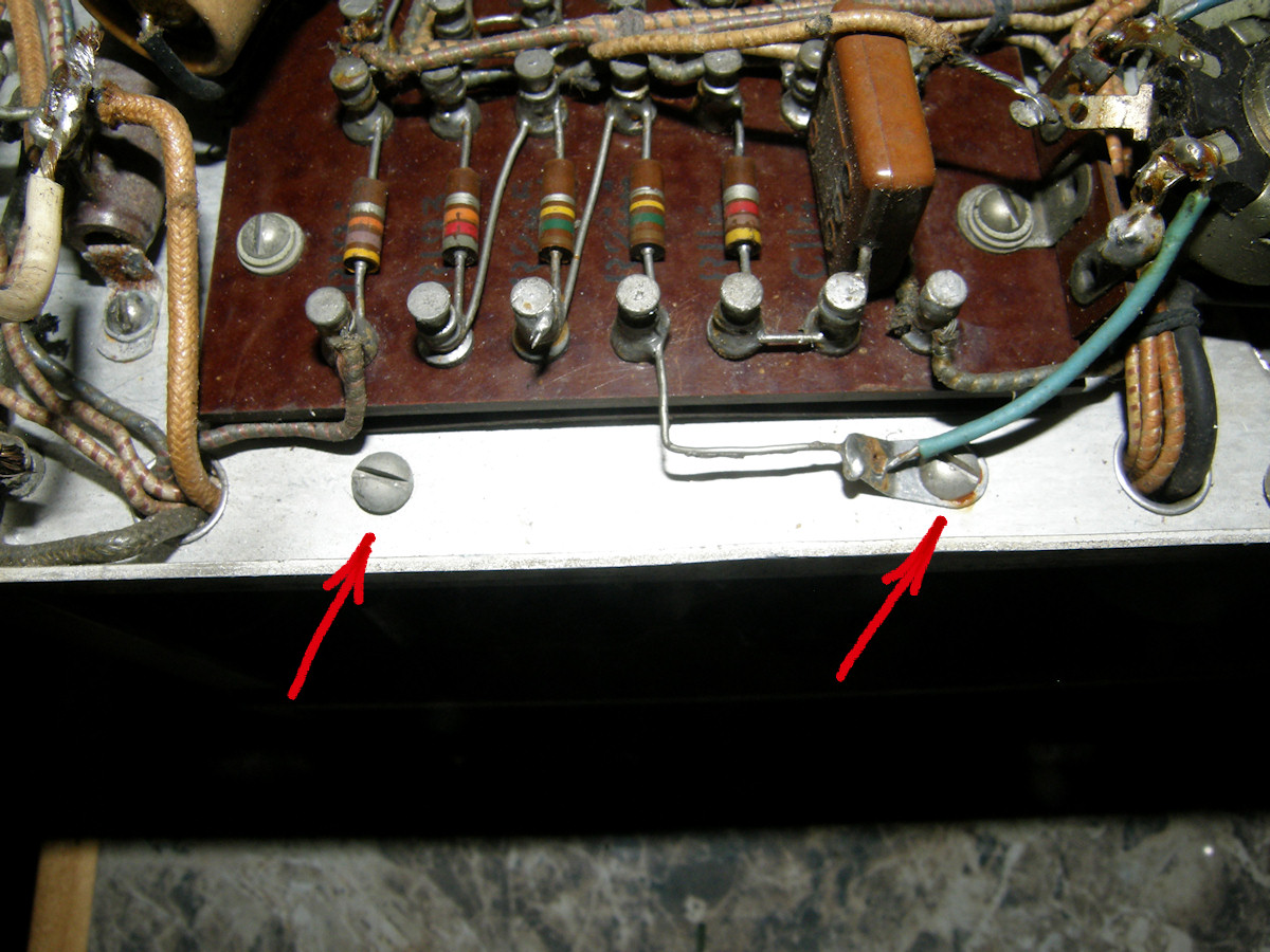
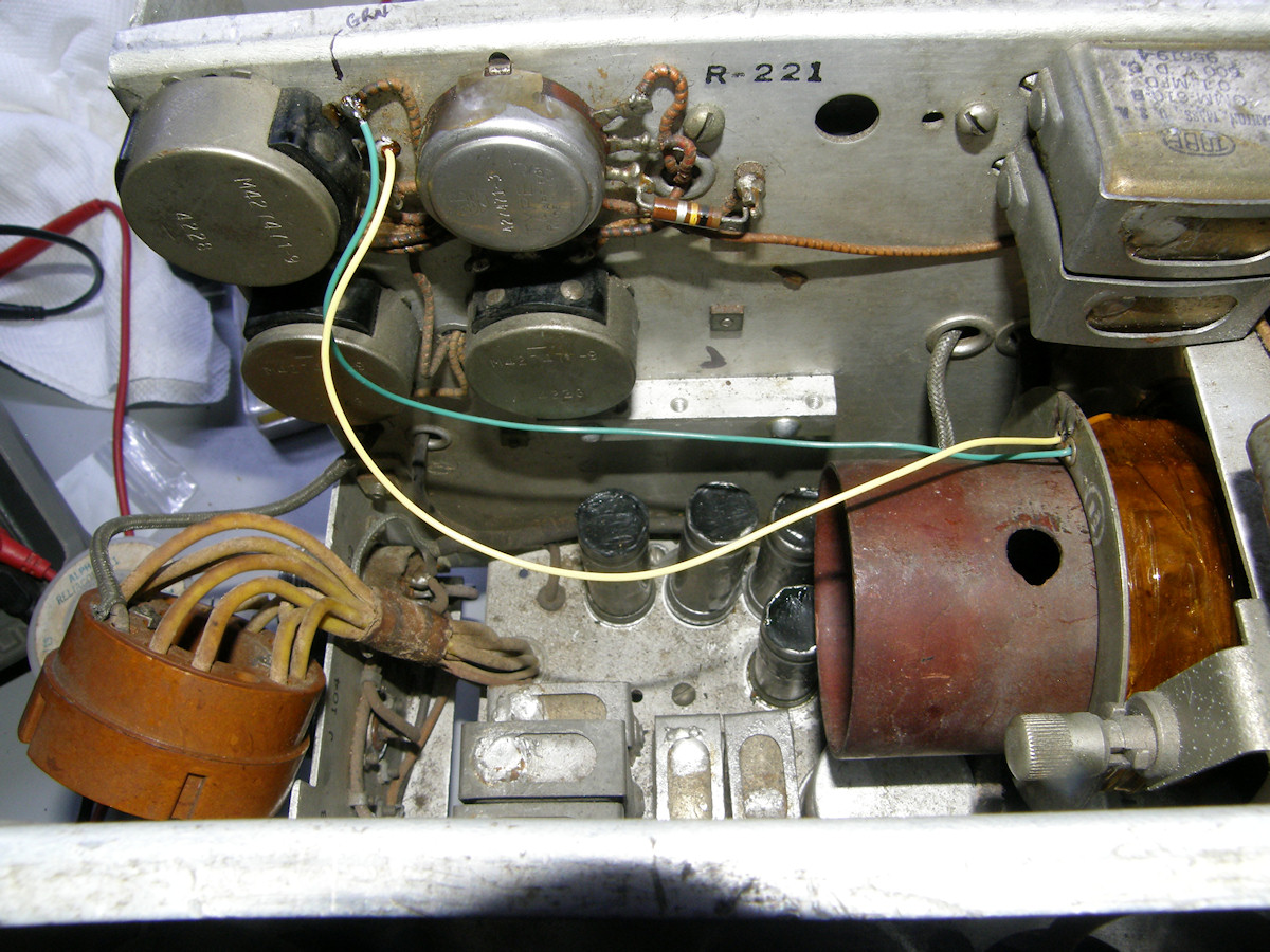
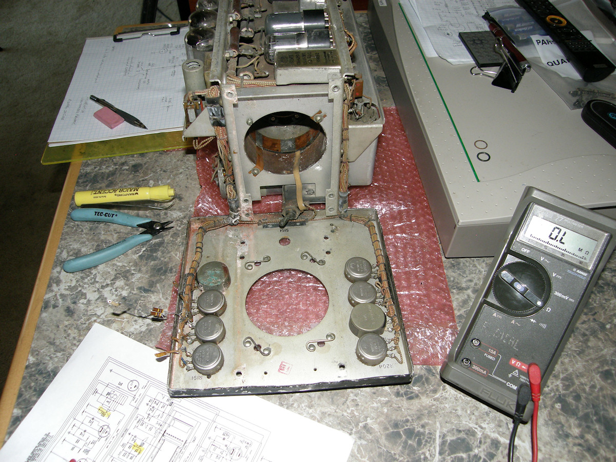
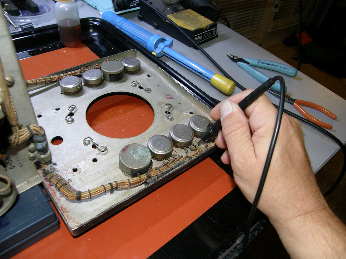
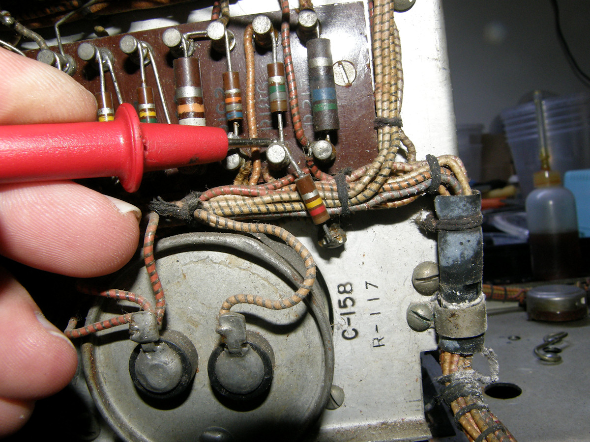
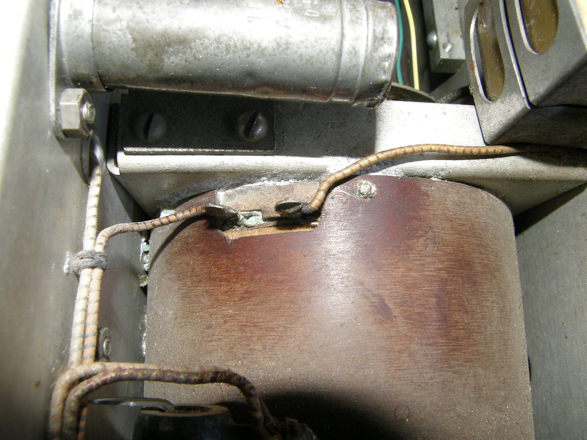
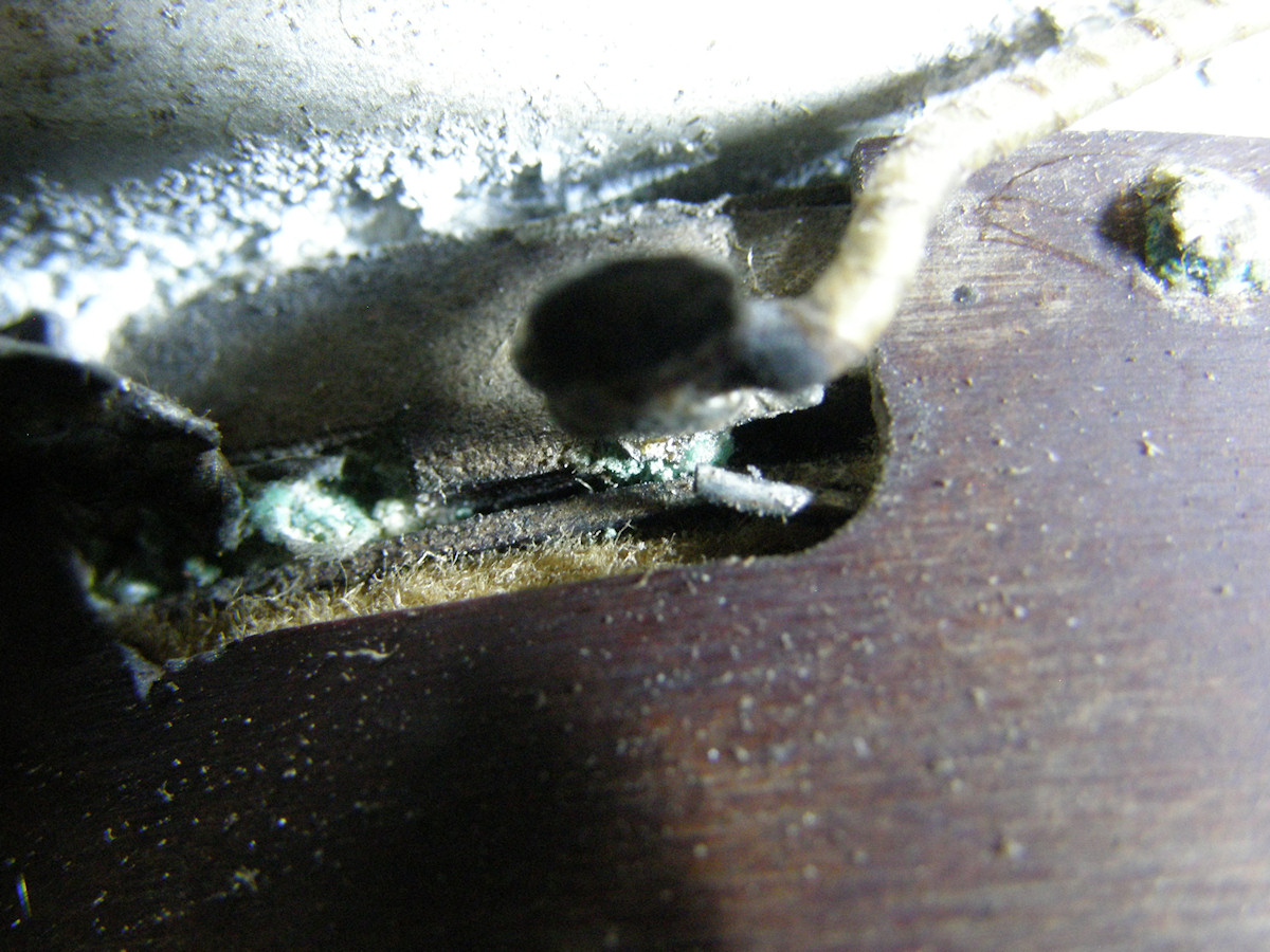
More trouble every day - 20150920 First photo. This is looking at the bottom of the camera just below the back end of the image orthicon tube. This is where the six remaining high voltage capacitors live, as pointed out by the red arrows. In order to access their mounting screws, I had to pull out the IO tube, and remove the tube and yoke clamping brackets. While performing this task, I made another disappointing discovery. Second photo. Dry rotted wires! Natural rubber insulated wire from the 1940s. The rubber has turned literally into sand. This is normally no problem. Just trace the wires out and install new. Easy peasy. Not this time, Bub. These two particularly sad wires emerge from the very critical dynode alignment coil! Just visible to the right side of the photo. I guess we are going to find out if Labguy can repair an antique image orthicon alignment coil. We have some excellent silver plated, teflon insulated, high quality wire for the job. Right after we rebuild all of these capacitors. Yikes! The fun never ends. 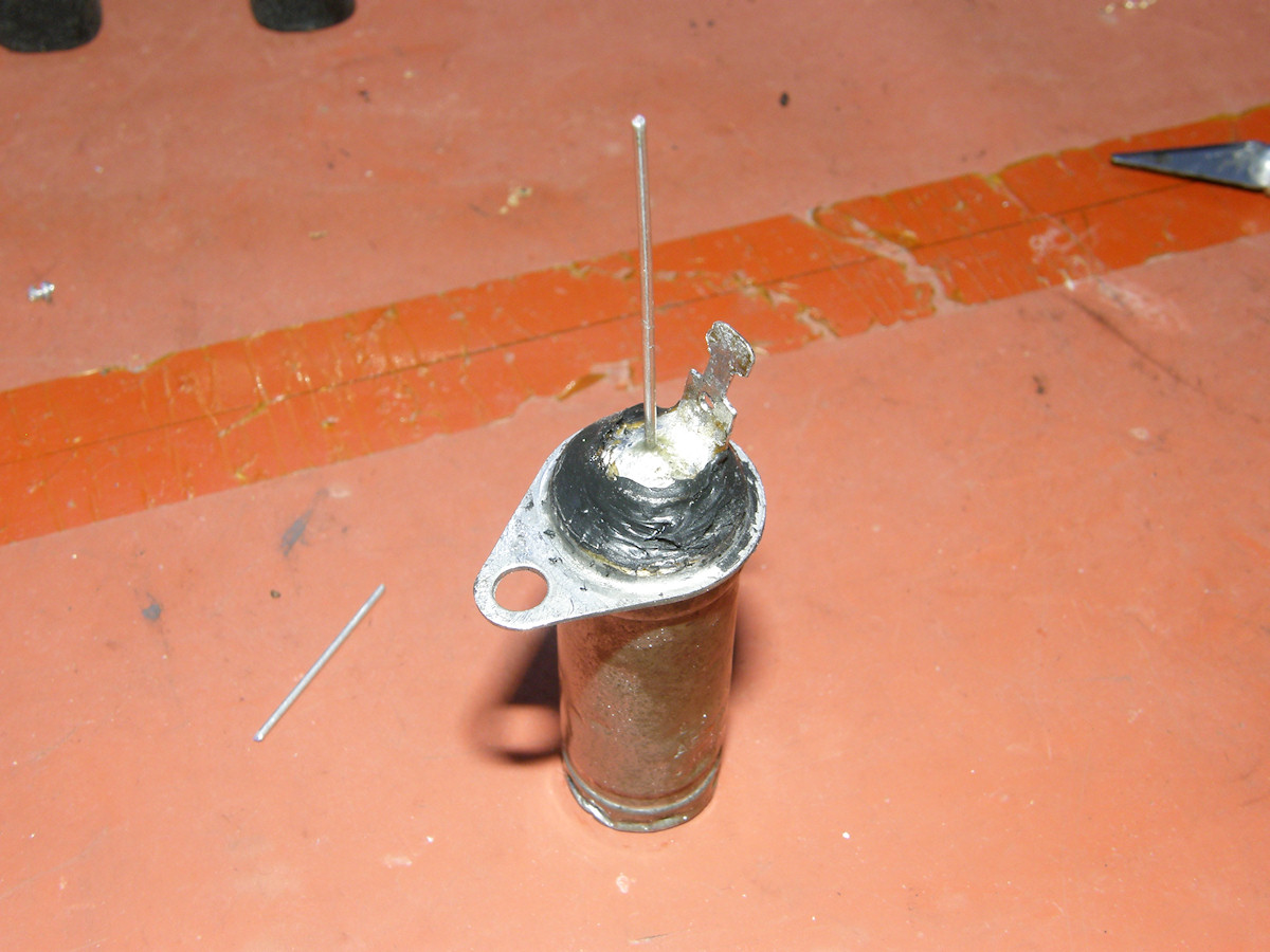
The rebuilt HV capacitor goes home - 20150921 Change of plans. This will be the only capacitor I will rebuild at this time. As you can see, the rebuild went swiftly. I plan to to leave the back end of the can open for the time being. The remaining six capacitors will have to wait until I figure out what to do about the alignment coil wires. Rotten wires are an absolute show stopper! There is a silver lining to all of this. The alignment coil and supporting hardware are the very bits blocking direct access to the six high voltage bypass capacitors. What a convenient coincidence! 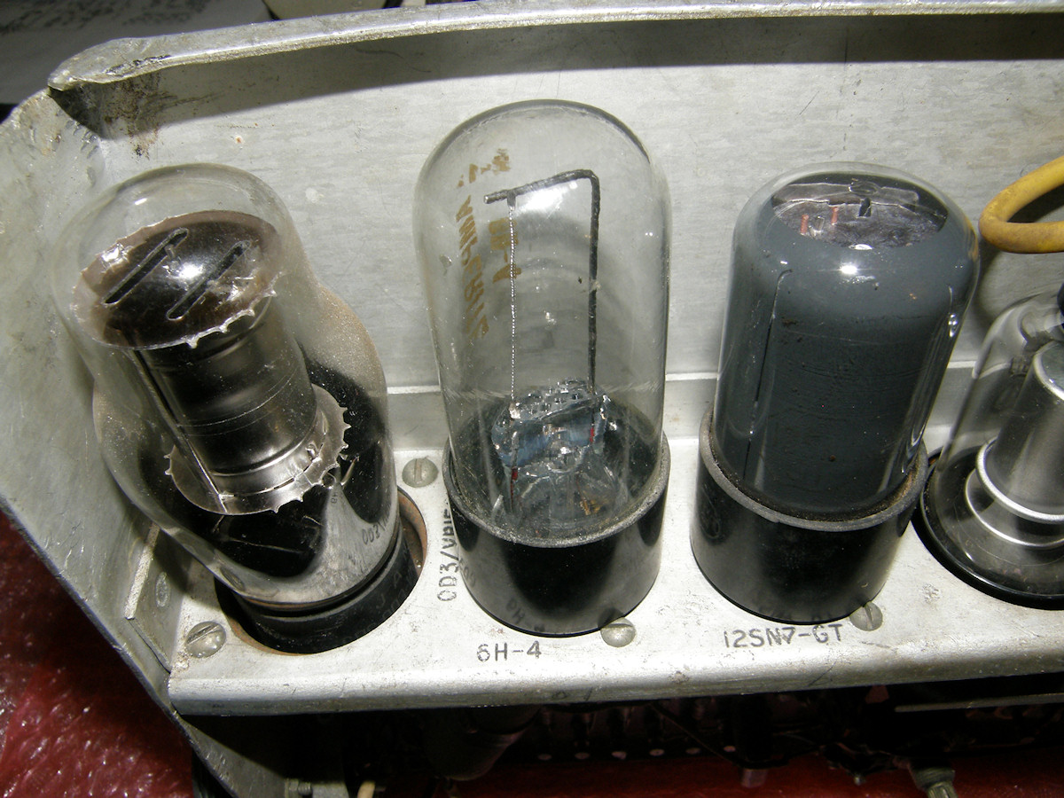
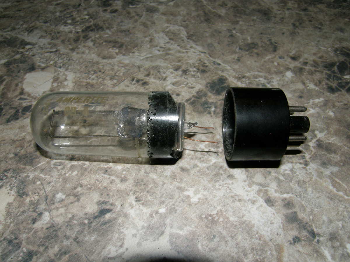
DOH! - 20150923 Found another annoying broken part. At least its easy to replace. There is one odd looking tube, called a ballast, that looks like a tube that has only a heater inside. It is actually a constant current resistor. How clever! This one, a 6H-4 is actually available on line for a good price. Phew! It serves as the focus coil current regulator in this cameras. I pulled the 6H-4 from its socket to clean the chassis a bit. When I did, the bulb pulled out of the base! Both wires pulled out of their respective pins. However, I used absolutely no force! The darn thing has been broken for some time. Such is the life of the restorer. Ordered a [replacement Amperite 6H-4] tube this morning. Apparently the last one in stock. Lucky Labguy! 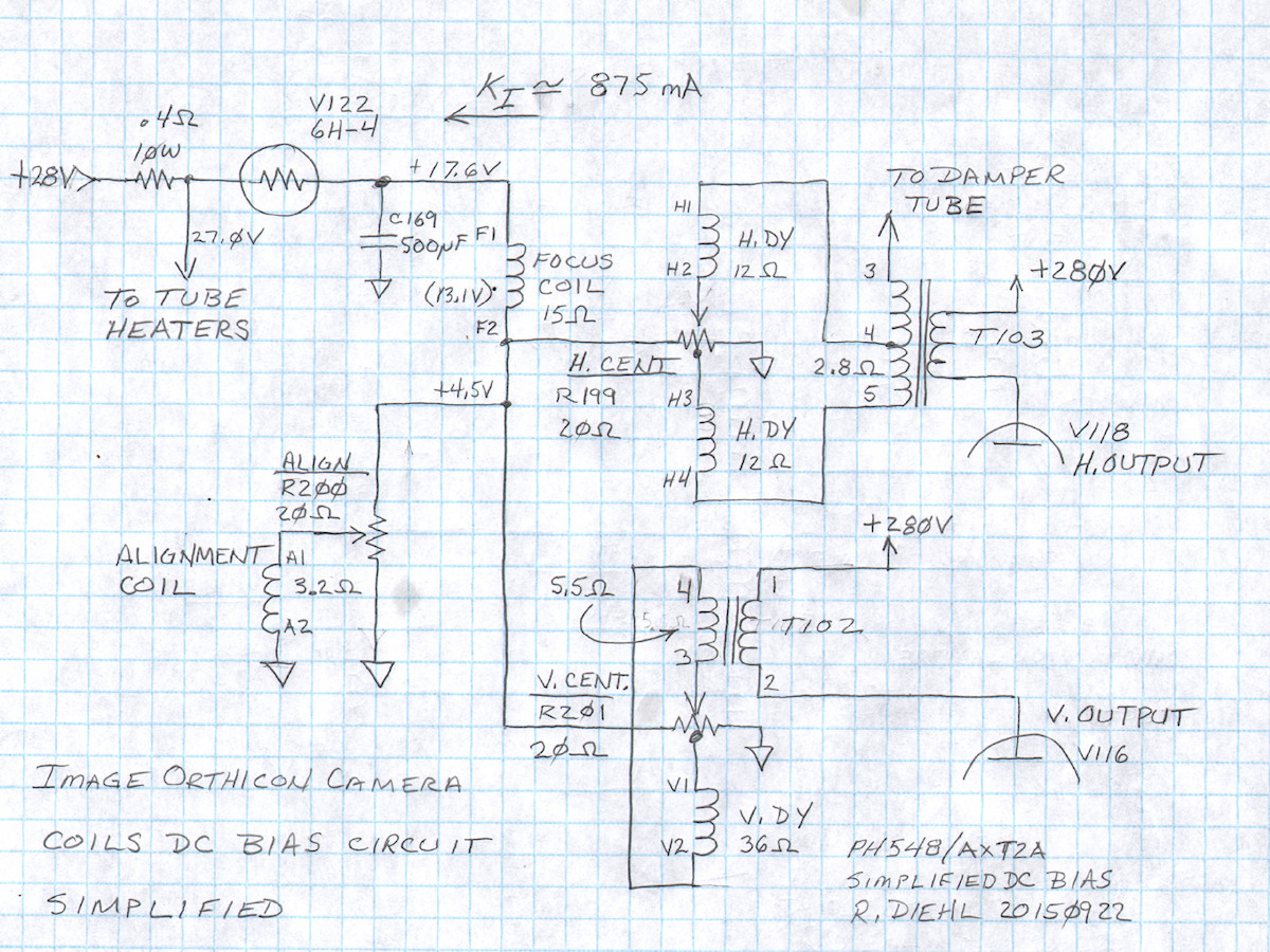
Labguy, what does the 6H-4 ballast tube do in this camera? - 20150923 V122, the 6H-4 ballast tube is responsible for regulating the series DC current through all of the image orthicon's electro-magnetic coils. Without these coils, the IO tube makes a great desk ornament! There are four sets of coils used in this design. There is the horizontal deflection coil, the vertical deflection coil, the focus coil and the alignment coil. Each serves its specific function. The focus coil and alignment coil operate on fixed DC currents. The horizontal and vertical deflection coils operate on AC currents. A small amount of DC current is summed into the deflection circuits to allow for centering the scan inside the image orthicon. Generally speaking and referring to my diagram above, everything to the left of the horizontal and vertical deflections coils (H.DY and V.DY) is DC. Everything to the right of them is AC. The AC signals are coupled through the two transformers, T102 and T103. Note how the centering controls, R199 and R201, are center tapped. The deflection coils, their output transformer secondary windings, centering pot's tap and wiper are all wired in series. With the centering control set to its middle postion, no DC current flows in the deflection circuit. A quiescent current of 225 mA is flowing through each centering pot. As the wiper is gradually rotated from center, some current begins flowing through the yoke and transformer. The polarity of the current depends on whether the pot is rotated to the right or the left of the center position. This gives the effect of moving the scan raster up and down, left or right on the face of the glass target in the image orthicon. The alignment coil is unipolar and only the magnitude of the magnetic field can be changed with R200. This coil is set on the neck of the tube just above G3. This is the entrance to the voltage multiplier stages. The field strength of the coil combined with the G3 voltage to find "just the right spot" for producing the best image. The alignment coil and G3 direct the return electrons into the multiplier evenly all the way around the outside of G3. Alignment field and G3 are adjusted for the flatest shading in the image. The focus coil is in series with all of the circuits perviouly mentioned and sees a constant current of about 875mA. I determined this value with Ohm's law. (17.6V - 4.5V) / 15 = .87333333333 amps. Rounded to 875mA just because. The conclusion is that V122, the 6H-4 ballast, is rated for that amount of current in this design. All of the circuit downstream of the 6H-4 are expending 15.4 watts of power. The 6H-4 is disipating 8.225 watts. This gives a total power in this circuit alone of 23.635 watts. 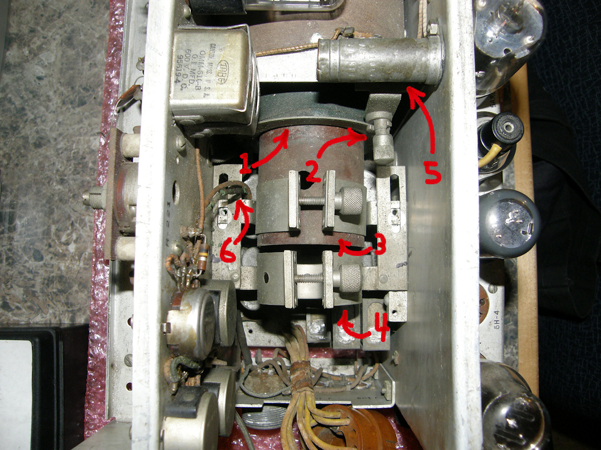
Labguy prepares to perform his famous Alignmentcoilectomy... - 20150925 ... an extremely delicate operation to be sure. To get to the Alignment Coil (1) to repair the rotten wires (6), we need to remove the IO tube clamp (4), the yoke clamp (3) and the alignment coil rotation lock screw (2). This is held in by two screws (5) which are not visible beneath C168, the recently rebuilt capacitor. At that point, the alignment coil should slide backwards freely from the liner tube. But... 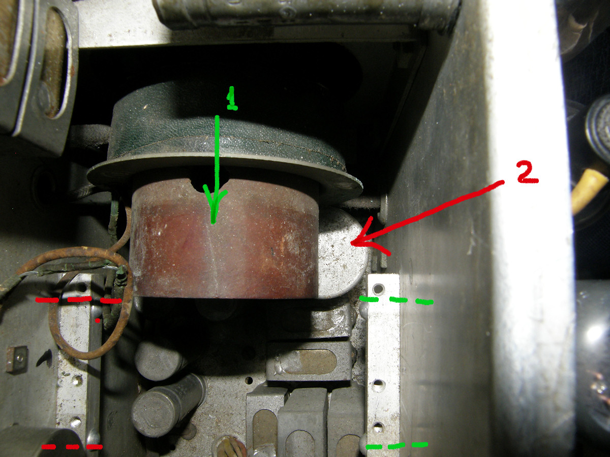
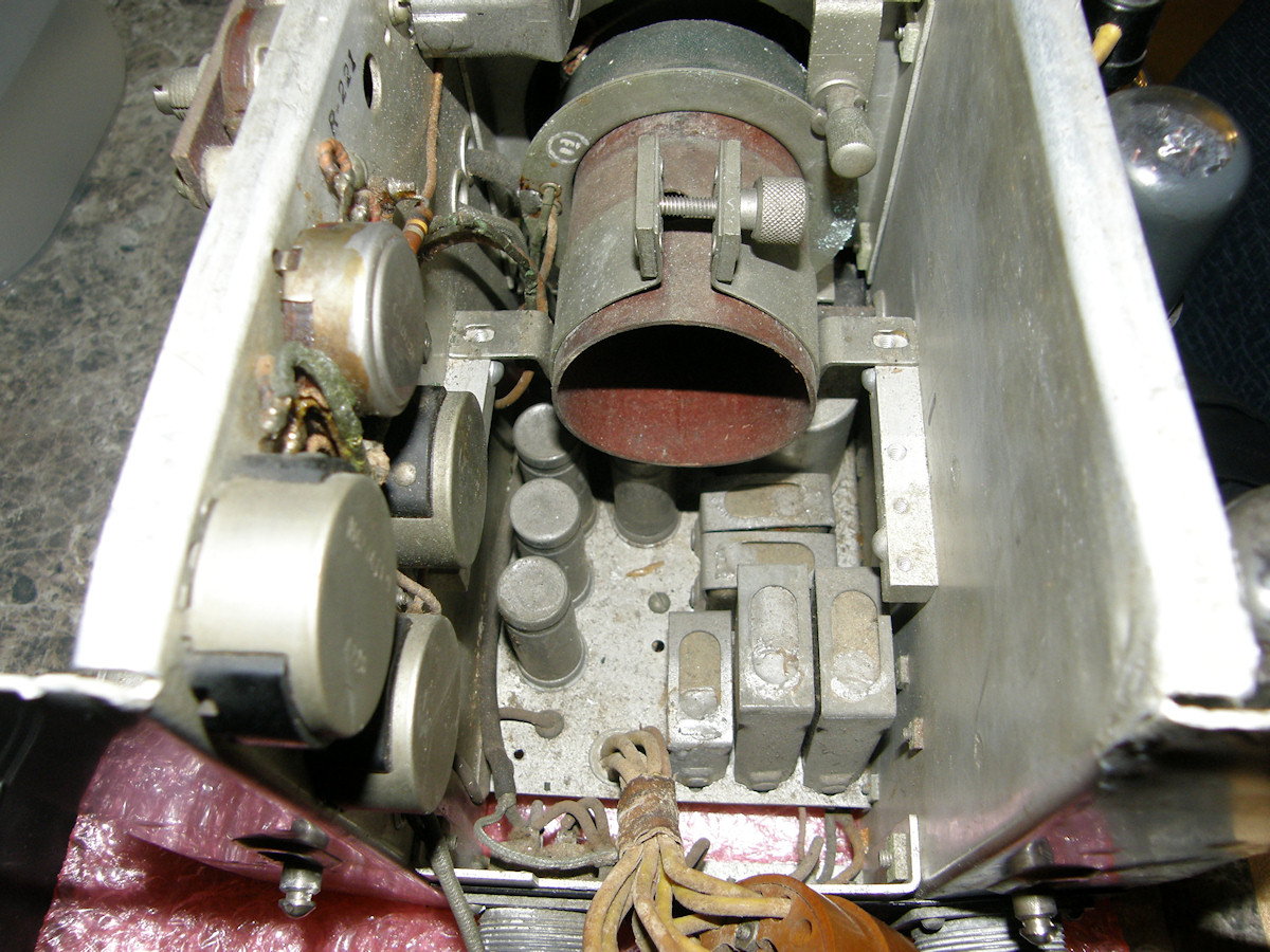
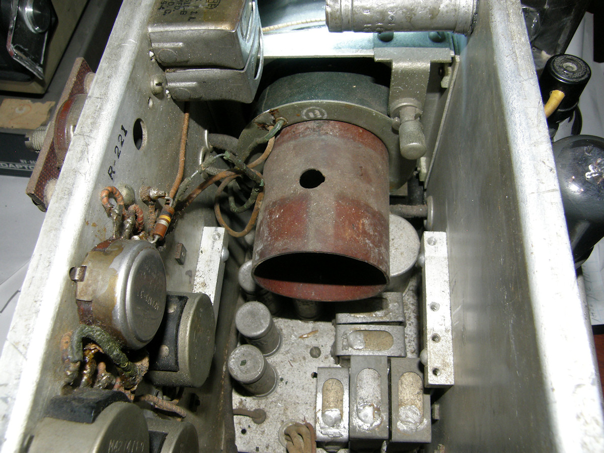
Persistence is the secret of success! - 20150925 There is a capacitor (2), located beneath the yoke liner tube, that is blocking the alignment coil (1) from sliding off the liner. The chassis that holds the offending capacitor is held in by four screws. Two on the left (red dashed lines) and two on the right (green dashed lines). The two screws on the left are not accessable. I removed the two screws on the right (red arrows, photo #2) and was able to push that side of the chassis far enough down to slide the alignment coil past the capacitor and off the end of the liner tube. That's what I call moving the project forward! 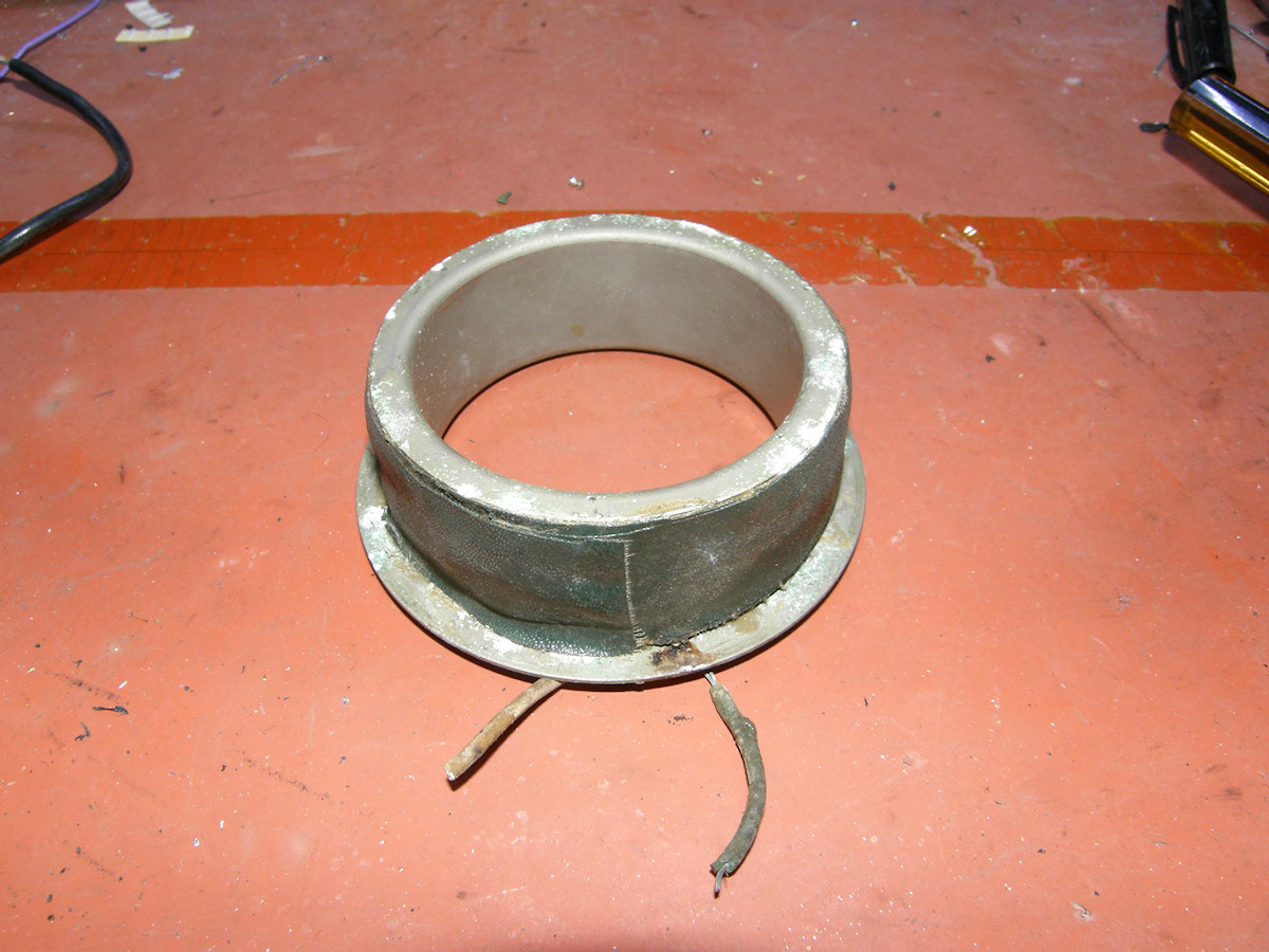
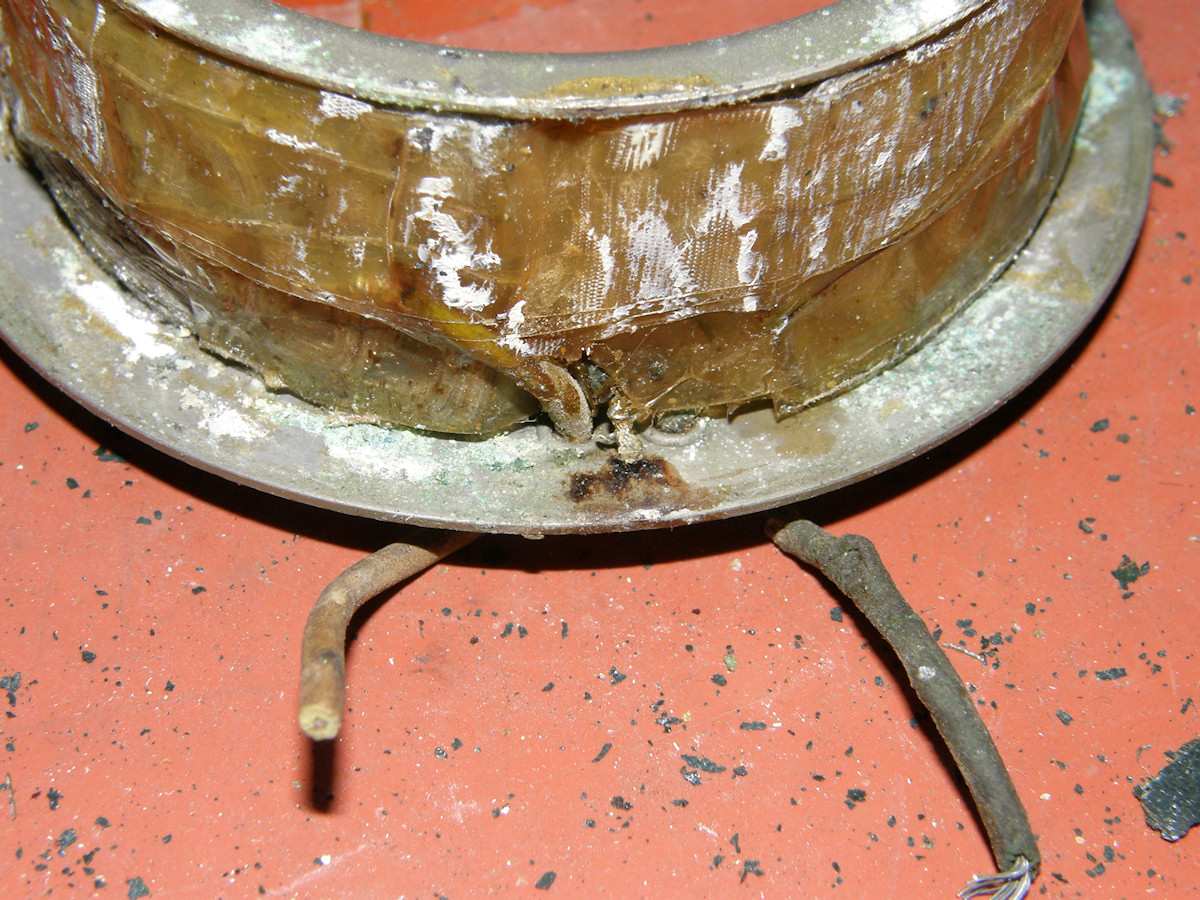
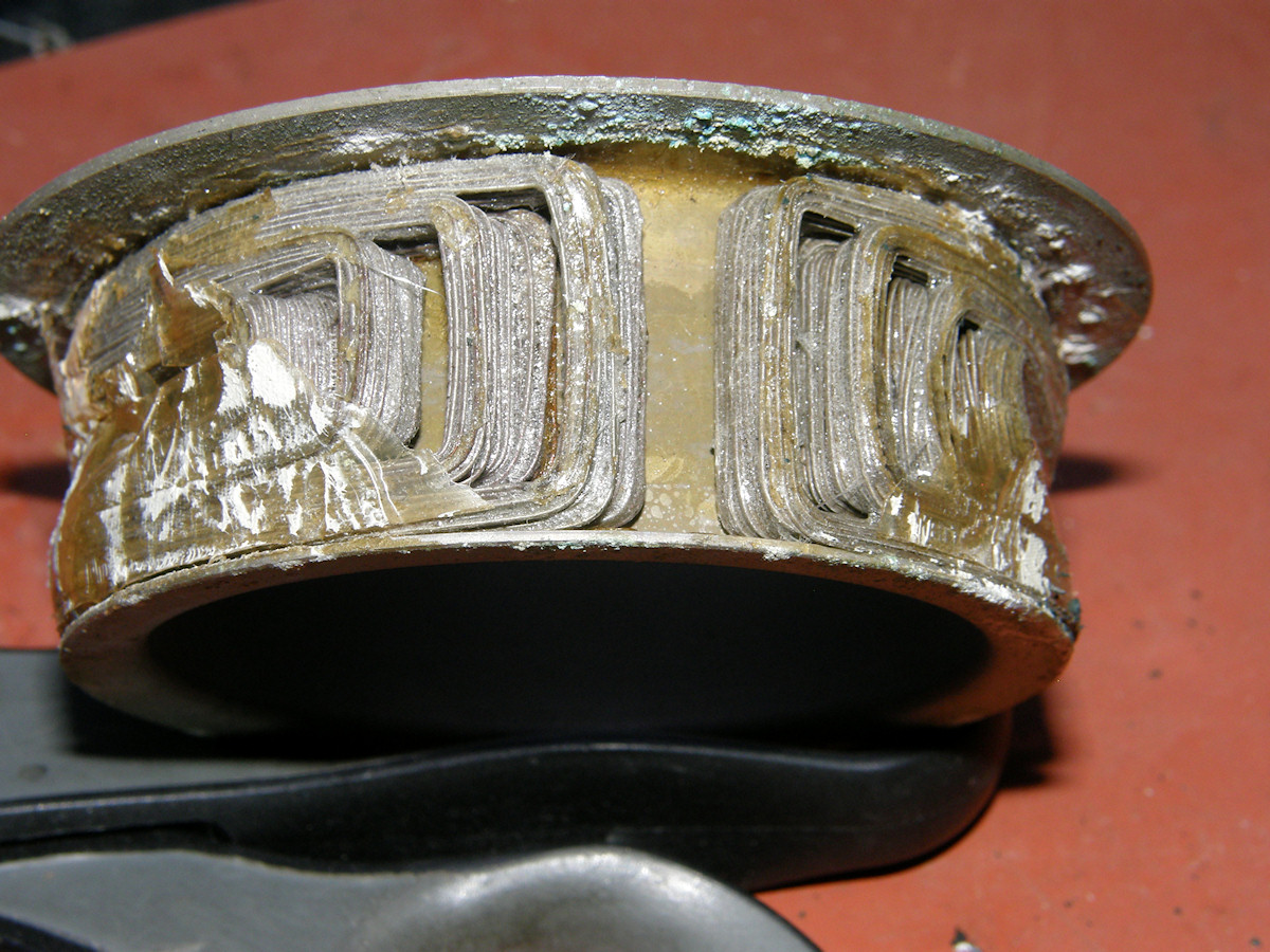
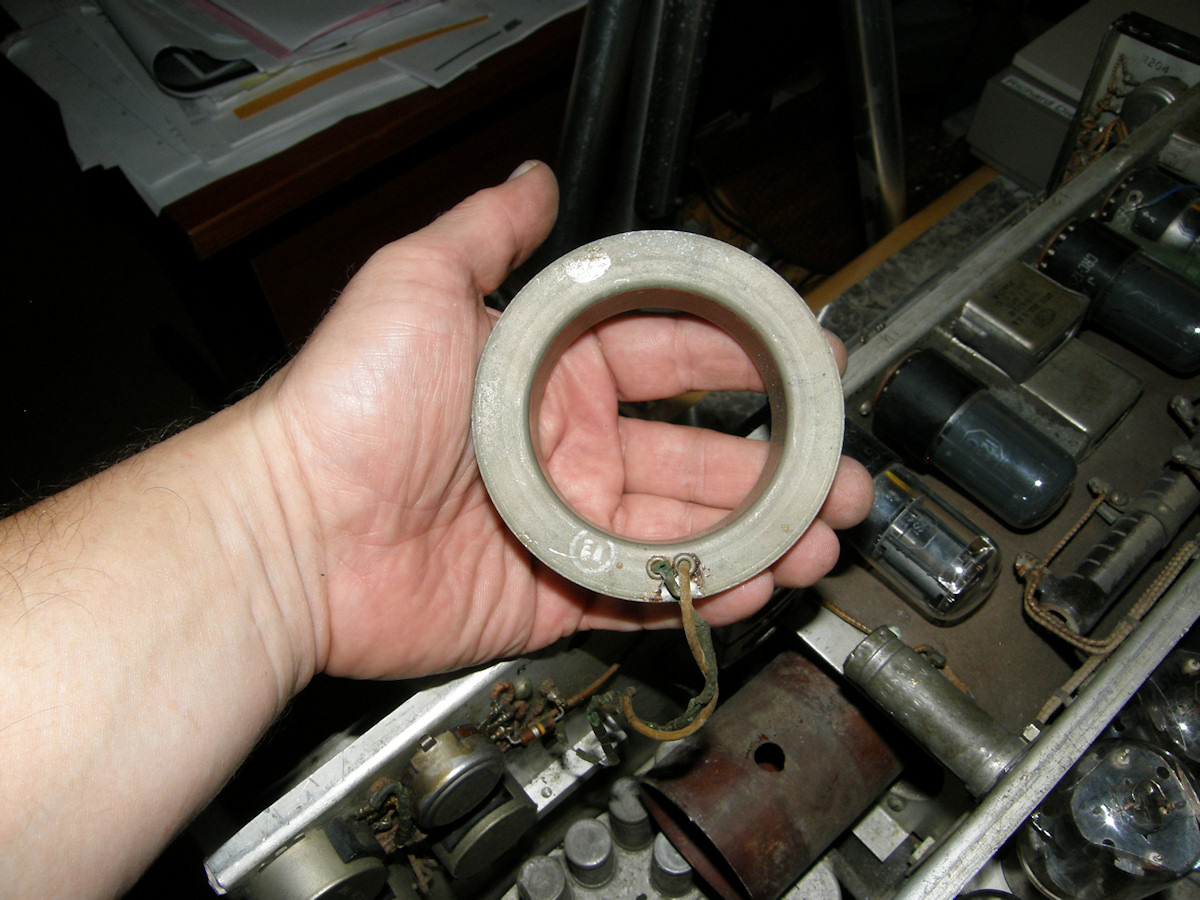
Let's unwrap this mummy, shall we? - 20150925 Found an interesting nested rectangular coil design. What is the shape of the magnetic field inside the IO tube? How does this work precisely? What I first thought was a short to the casing turned out to be where the ground wire was attached to it. The green rotten wire is at ground potential after all. But, it is exposed, can short to other hot wires and will be replaced anyway. I am not sure what to make of the insulation on the magnet wire. I can't say I have ever seen it this color and condition before. I am wondering if that coil has been overheated at some point and is damaged or if it is just some funky laquer used during WWII? The schematic says the coil is 3.2 ohms. This one measures 28 ohms which, in my opinion, is actually a more realistic value. It is odd that the load resistance on the voltage divider pot R200, is smaller than the value of the divider. It is usually the other way around. We will certainly find out on the day that power is reapplied to the circuit. 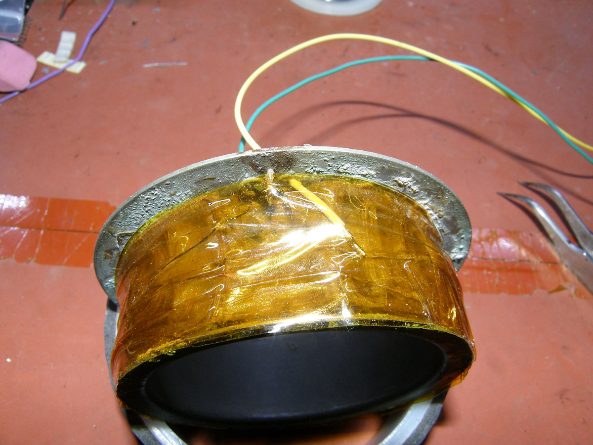
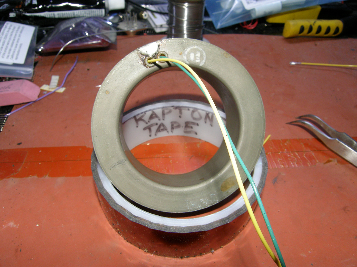
Let's rewrap this mummy, shall we? - 20150926 After removing the old wires and soldering in modern teflon insulated wires, I re-wrapped it all in Kapton tape. That's the stuff all the Mars rovers are wrapped in. Amazing stuff, [Kapton tape]. I doesn't freeze, melt, or rot (that I know of. Perhaps I can't live long enough to find out!). The tape has excellent high voltage and high temperature performance and is perfect in this application. The alignment coils is now repaired and can go back into the camera. But, first there seesms to be a nagging memory of some rotten capacitors that need rebuilding? 
A quick look at the circuit with all the high voltage capacitors - 20150927 Before I remove the high voltage capacitors in preparation to rebuilding them, let's take a moment to examine the image orthicon high voltage bias circuit. Specifically the bias voltages and associated image orthicon electrodes operated by those voltages. I am presuming you already know or you have watched my video on [how the image orthicon tube works]. The high voltage is generated by T104, V120 and capacitors C168 and C155. Between the two capacitors, C168 and C155, a total of almost two kilovolts (1,960 volts) is created. The series current flow in the circuit is as follows. Starting at ground potential at the top of R204 (BEAM), the current flows down through R204, R185 (IMAGER FOCUS), then back up through V122, T104, R212, then back down through R207, R208, R209, R210, R211 and finally returns to ground through the +280 volt power supply. The -500 volt side of the power supply operates the image section of the image orthicon. The photocathode is operated at the most negative potential, about -250 volts. The photocathode is where the imaged photons are converted into electrons. No photons, no electrons. More photons, more electrons. This effect is instantaneous. If the photocathode is scanned directly, it can only convert the signal present at the very instant the scanning beam passes a given point. That can literally be two or three electrons sampled in roughly 250nS! Not a very strong signal. If only we could store the charge for every point, over the whole frame, and then scan it. Imager Section G6 behaves as an accellerater to propel the electron image toward the glass target. The collomating parallel magentic field produced by the focus coil keeps the electron image perfectly perpendicular to the target. The photocathode's function is light conversion and the glass target's job is to provide charge storage between scans. When the scanning beam samples the points on the target now, the charge present has been accumulating for the entire field or frame time since the last scan. That can be up to 32mS. Call it first stage gain. The positive side of the power supply operates the electron multiplier section of the image orthicon. The second stage of gain in the image orthicon tube. Starting at Dynode #1, each successive dynode is about three hundred volts more positive than the preceding one. This makes the electrons cascade multiply through secondary emission impacts with each successive dynode. Total multiplier gain is reputed to be about 500. This is an average of about 3.3 electrons emmitted from each dynode for each single electron received. The Anode is the last stage in the multiplier chain. It is the source of the tube's output signal. The multiplied electrons form the output video signal. This signal is AC coupled to the video amplifier via C146. The capacitors I will be replacing are C147, C151, C152, C153, C154, C155, C156, and C168. A total of seven more capacitors to rebuild. C168 being already completed. Six more are hiding under the image orthicon yoke and one is located at the first tube in the video amplifier. With the Alignment Coil removed, the six capacitors beneath the yoke are accessable. Video: Rebuilding a high voltage capacitor (16:30) - 20150927 For those of you waiting, the video is finally out. Learn how I use all ten of my thumbs to rebuild this antique capacitor. I get to do it again six more times. Yippee. My deepest apologies to genuine purists who will most likely be appalled. The end result of my efforts will make the camera run better and will most likely be seldom seen. Thank goodness! 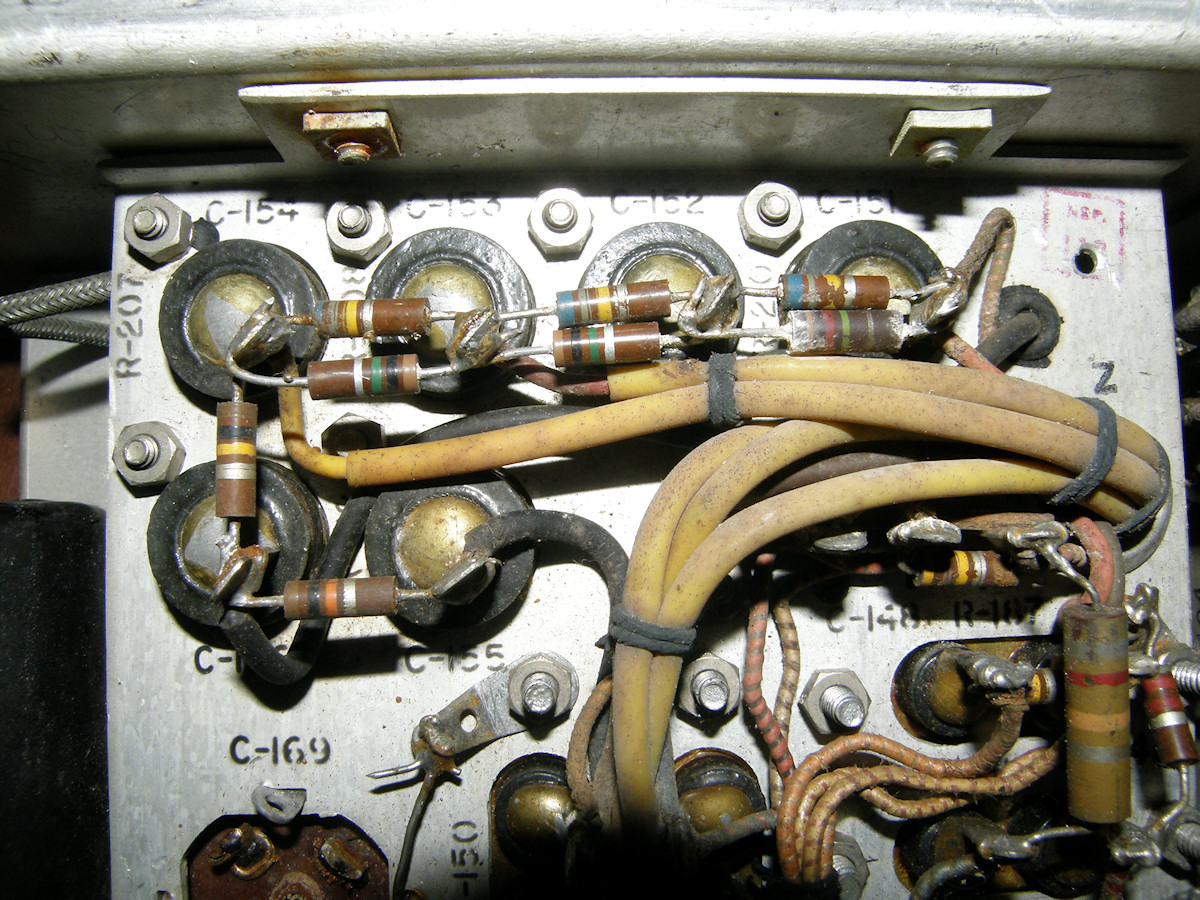
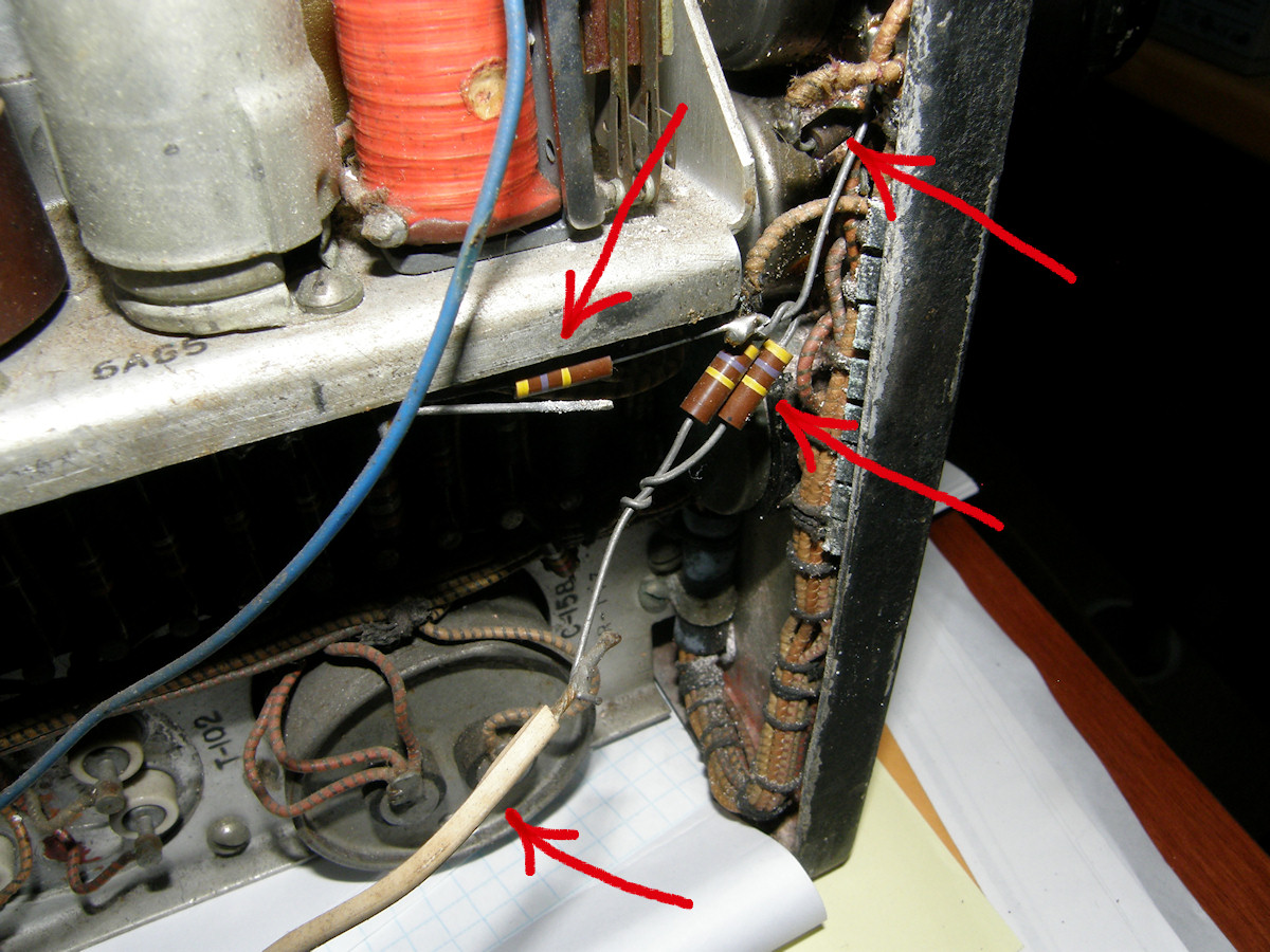
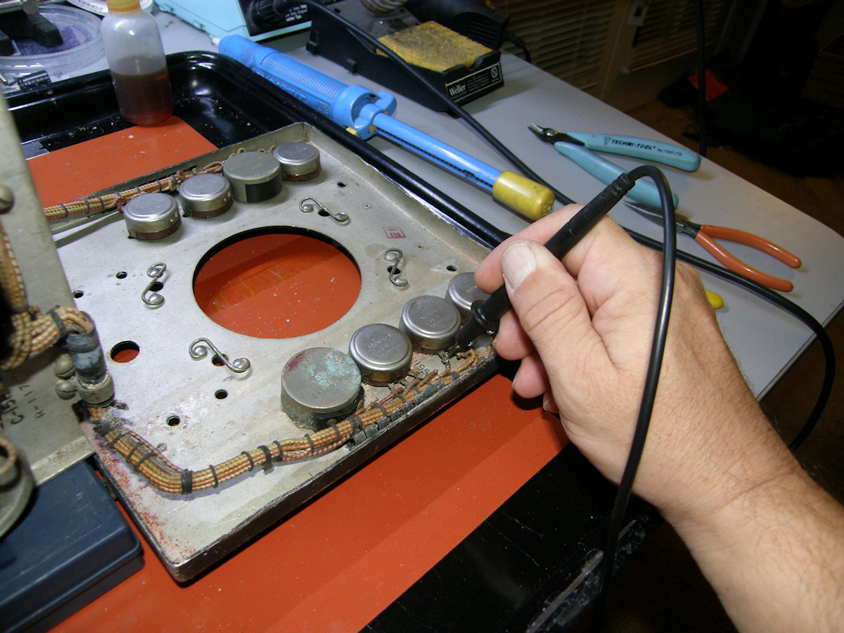
Our old friend has been here. Some added resistors - 20150927 Here again are the six remaining high voltage capacitors and the dynode resistor divider string. Someone has addeed parallel resistors at R208, R209, and R210. That's the three paired resistors attached to the four capacitors in a row. I'll remove these added parts and return the circuit to its original state. If trimming is needed later, we can deal with it then. But, for now, the point of this image is for me to have a map as I remove all those capacitors and resistors. I have determined it is tactically a better plan to remove all six capacitors together. If they are sequentially removed starting from the left, each successive capacitor's mounting screw becomes accessable to my fingers. They will come out left to right and go back in right to left. Easy peasy. 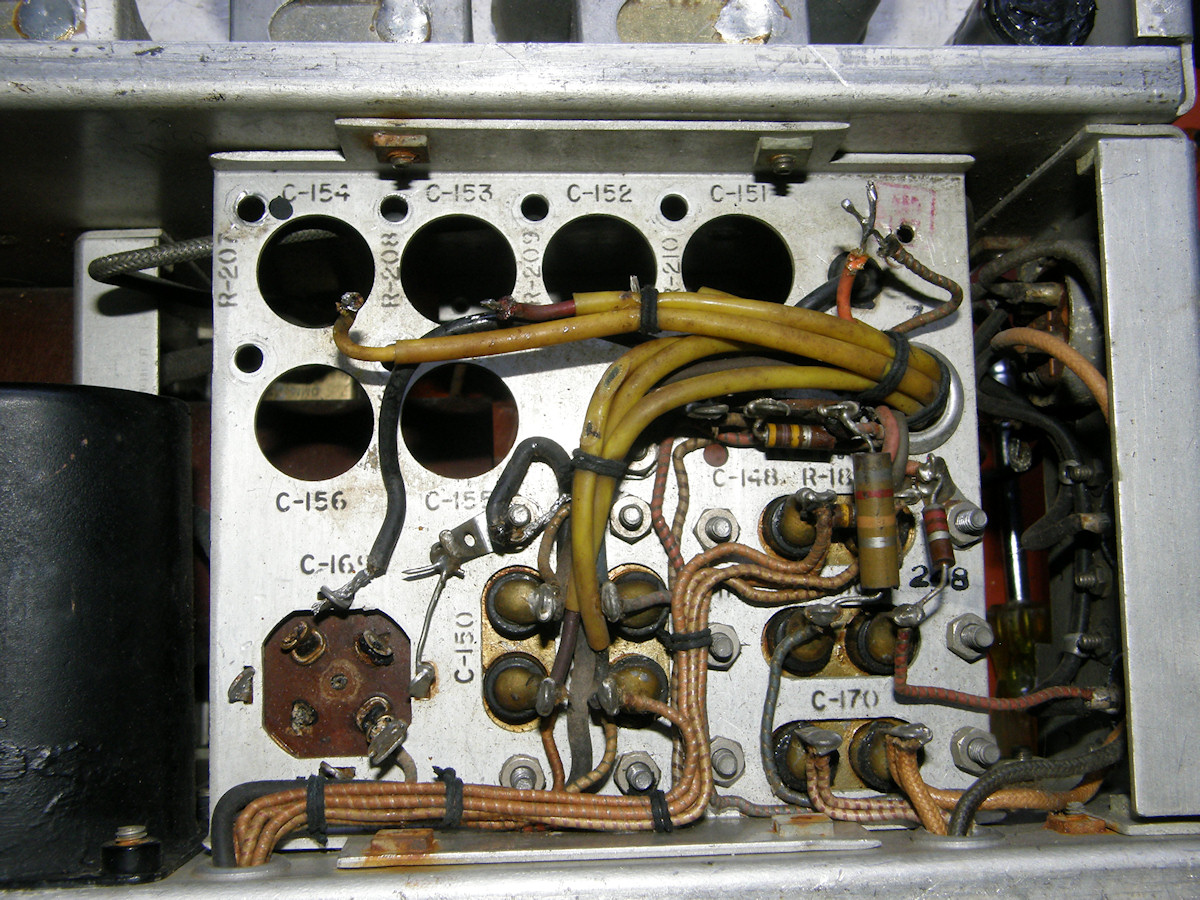

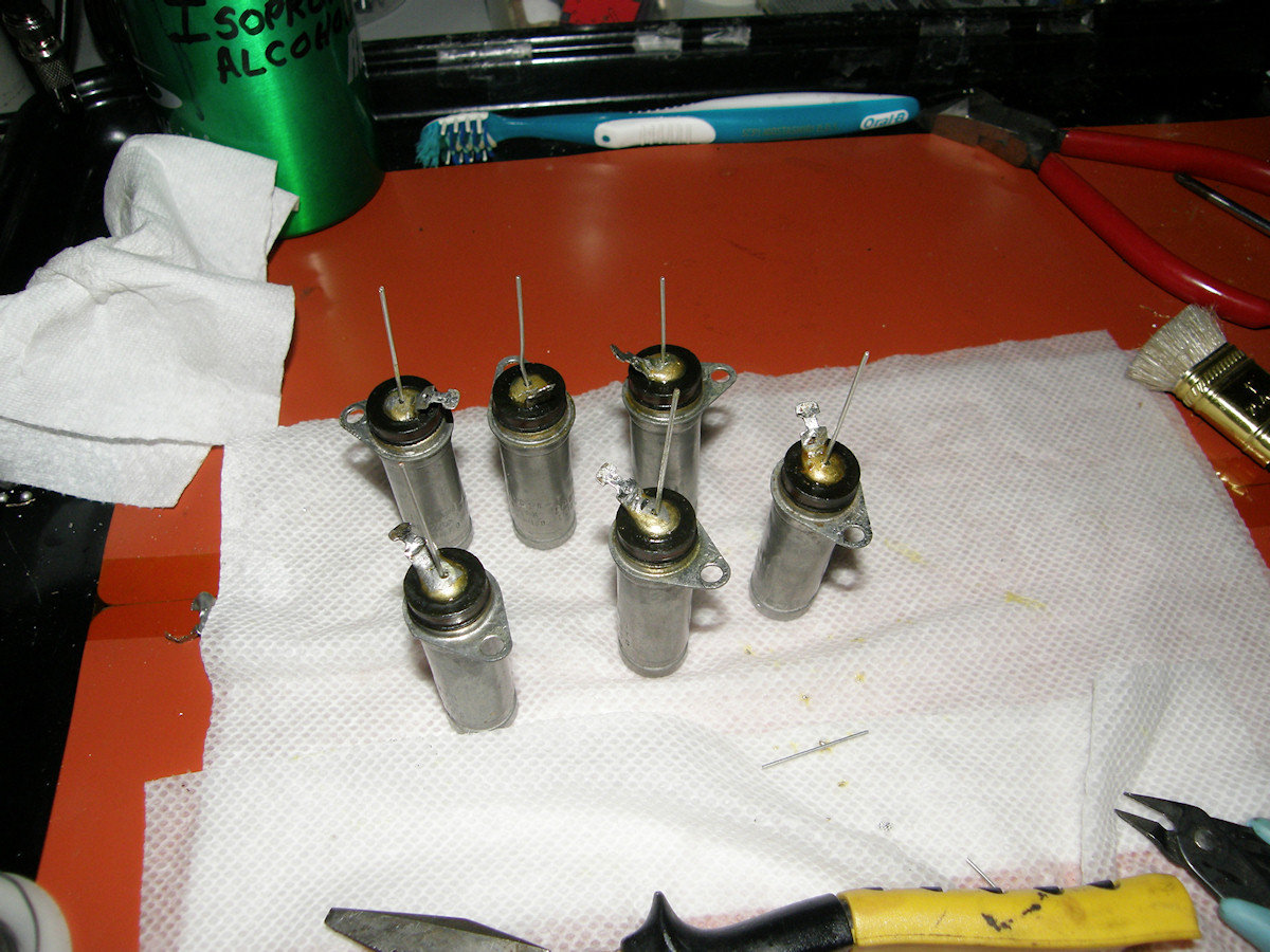


The six remaining capacitors get rebuilt - 20151003 You know how this works. These six capacitors suffered far less damage than the earlier pair. Like before, these were gutted, cleaned, refilled and sealed. After a 24 hour curing period, I will reinstall them in the camera. By bolting the capacitors together in triads, they become self supporting in upright direction. That's the perfect position for sealing them with silicone rubber. I considered trying to solder plugs in the end of them, as they originally were. That did not seem possible with the tools I have on hand. Plus I didn't want to risk destroying $30 worth of brand new capacitors. The silicone is practical for the job and a future restorer would have far less trouble with the silicone than I experienced with the soldered end plugs. Video: Re-installing the high voltage capacitors (12:00) - 20151004 We finally get the last six high voltage capacitors reinstalled into the camera. I replaced all of the resistors in the dynode voltage divider circuit as well. We can finally move on to the other issues in the queue. Like reinstalling the repaired alignment coil. 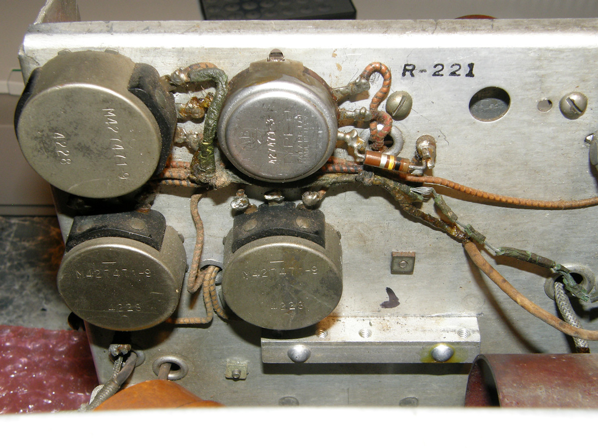
Alignment Coil old wires and new - 20151007 I removed the old melted wires from R200, the Alignment (coil current) Control. Fortunately, there was no damage found in the other wires that shared the laced harness with the old wires. After a bit fiddling about, I got the alignment coil back onto the yoke center tube and all hardware replaced. The plan is to leave the new wires outside the wiring harness in case there is still a problem and they overheat again. No need to do any more damage than necessary. It is already looking better! Video: Re-installing the Alignment Coil (12:45) - 20151004 The alignment coil gets put back where it belongs. Also known as the multiplier focus coil. It is used to steer the return beam electrons into the circular shaped aperture that surrounds the electron gun. If the return electrons are offset, as is caused by the deflection centering controls, then the image is shaded in the direction of the offset. This coil has field that is identical to a single deflection coil. It puts magnetic force right across the tube. This will "push" return beam one way or the other. Since it sits outside the deflection zone of the yoke, it is able to steer only the return beam electrons. It has a minimal effect on the main electron beam. Commercial television cameras used two alignment coils. One for horizontal and another for verticl correction. This camera uses a single coil and directionality is achieved by rotating the single coil and by varying the field strength. It would be able to fully rotate 360 degrees, limited only by the length of the wires. From this point forward, I will be tracing the schematic of the changes the previous fellow introduced. He hacked a lot of the circuits and these need to be inspected and repaired carefully. 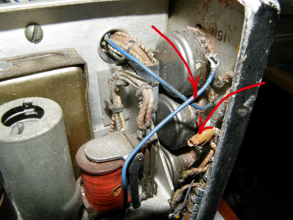
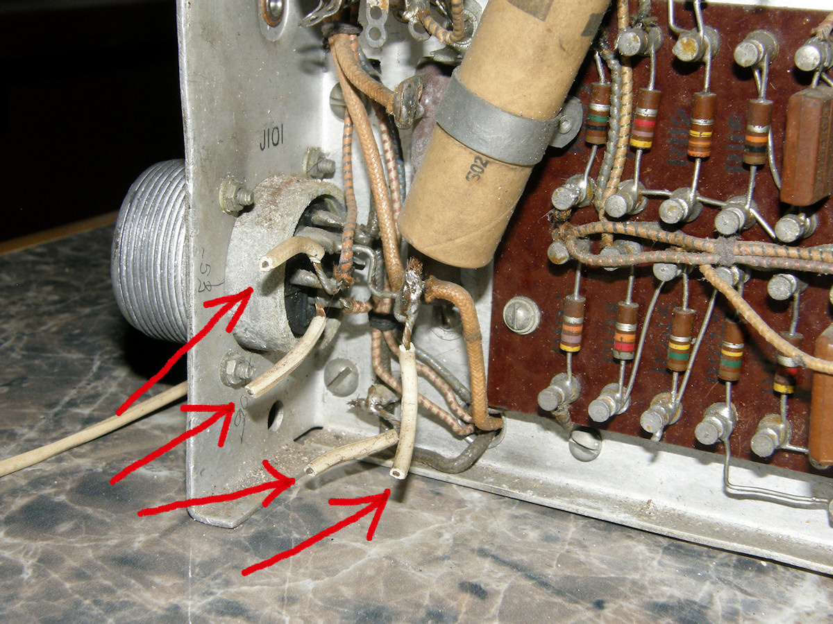
Unauthorized rework, forensic analysis - 20151010 The blue wires, lamp cords and dangling resistors are the legacy of the previous person who tried to make video with this camera. Most likely, the high voltage power supply did not work at all or it produced insufficient high voltage. Remember the funky rectifier tube? He most likely could not locate the called out tube, the 8016. (Life before the internet was brutal! Did you know this camera was actually [chipped from a piece of flint]?) The 8016 is simply a military graded version of one of the most common rectifiers of the day. Sheesh! So, the fellow connected an external high voltage power supply and tried to work around the failures that way? I get it. But, I don't like it. None of the wire the guy used is up to the job of withstanding thousands of volts. Most wire has an insulation breakdown of 600 volts or less. The blue wire is what was called "bell wire" because it is suitable for 24VAC low voltage door bells! It is never expected to be used at anything approaching those voltages. The lamp cord was most amusing of all. I used to do that. When I was 11 years old! Perhaps this is the work of a precocious young person. In that case... reasonably well done! 
Front panel access at last! - 20151010 Before just ripping out the rework, I traced out the added circuits for my own reference and curiosity. By removing the wires attached to R191, Orthicon Focus, the front panel could be detached and folded down for easy access. Beside R191, R185, Image Focus, was modified. Resistors were added and wires rearranged. I document the removal of all of this in the following video. Video: Removing the unauthorized rework from the camera (10:00) - 20151011 Watch me take out the modifications and do my best to reconnect the wires. Lots of soldering and hand tool work that most people don't get to see. Next step is verification of my own restoration. I will produce a list, from the schematic, of the points that will be checked with an ohm meter. I will verify that the contact on each of R191 and R185 are actually connected where they are supposed to be. Could it be that we are approaching a time when electrical testing may begin? 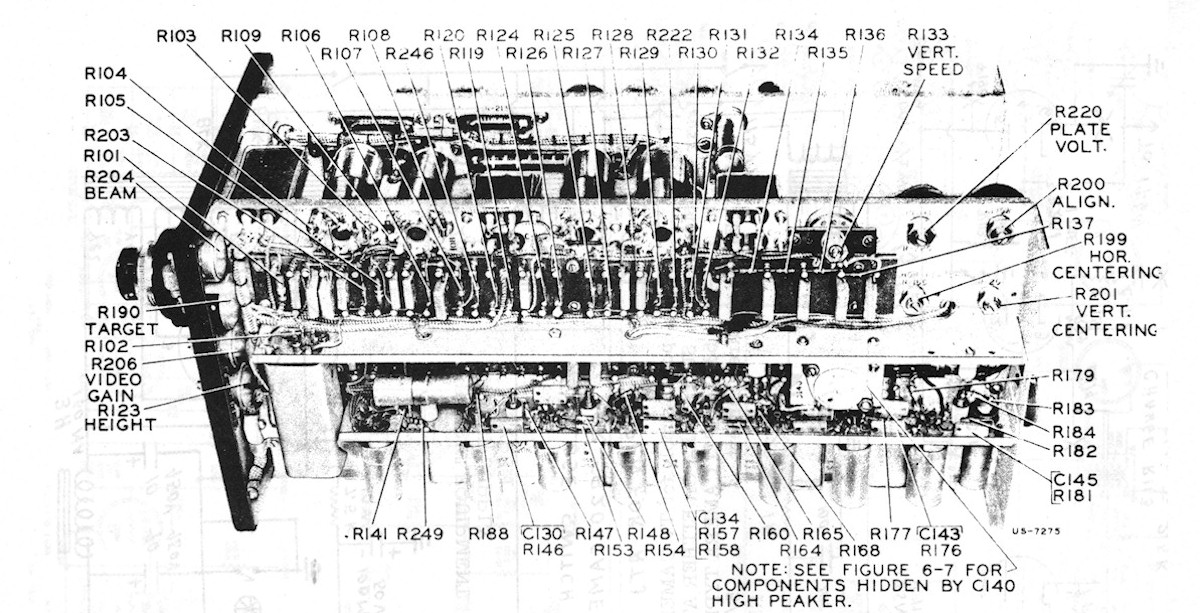
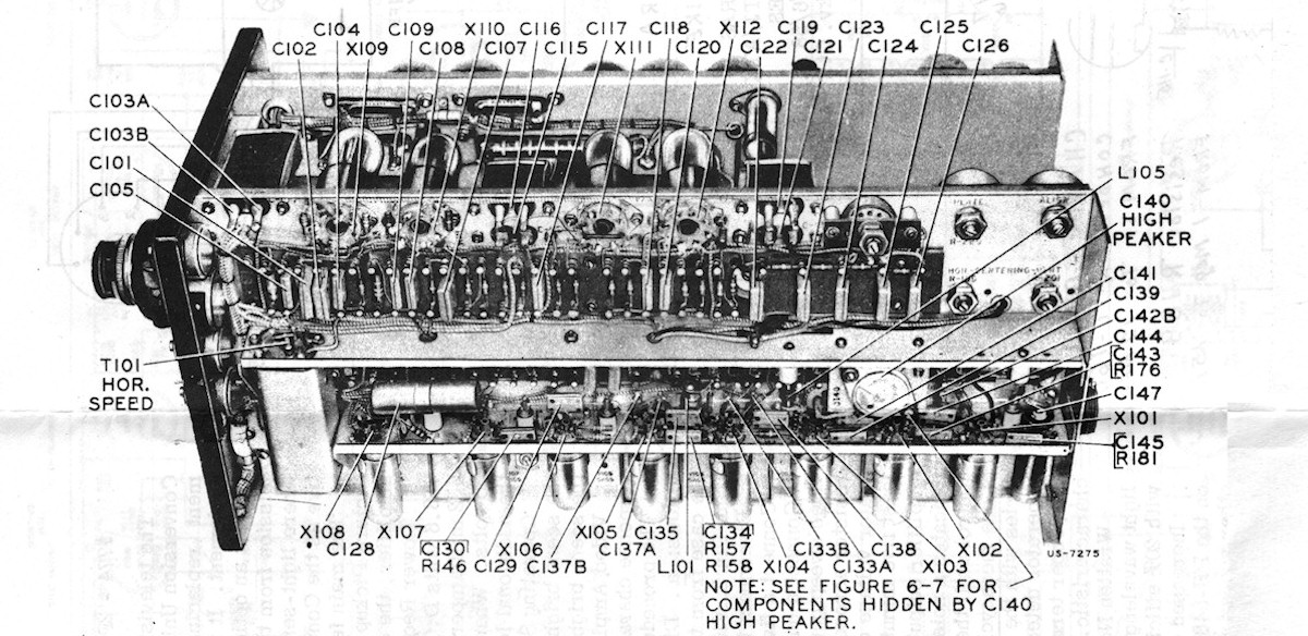
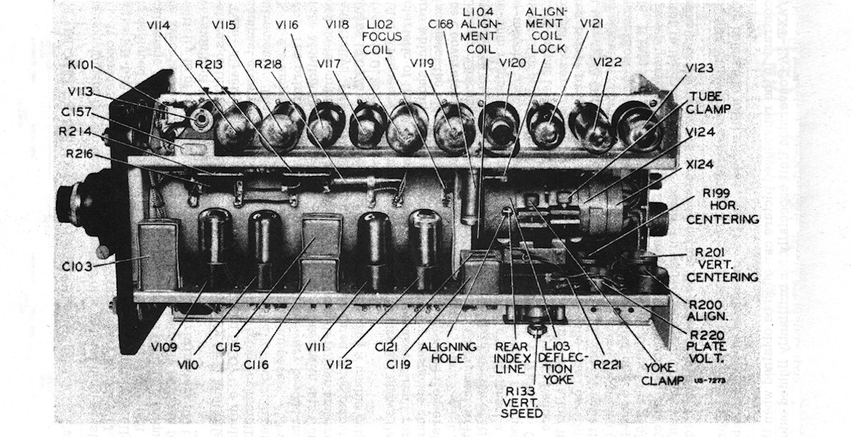
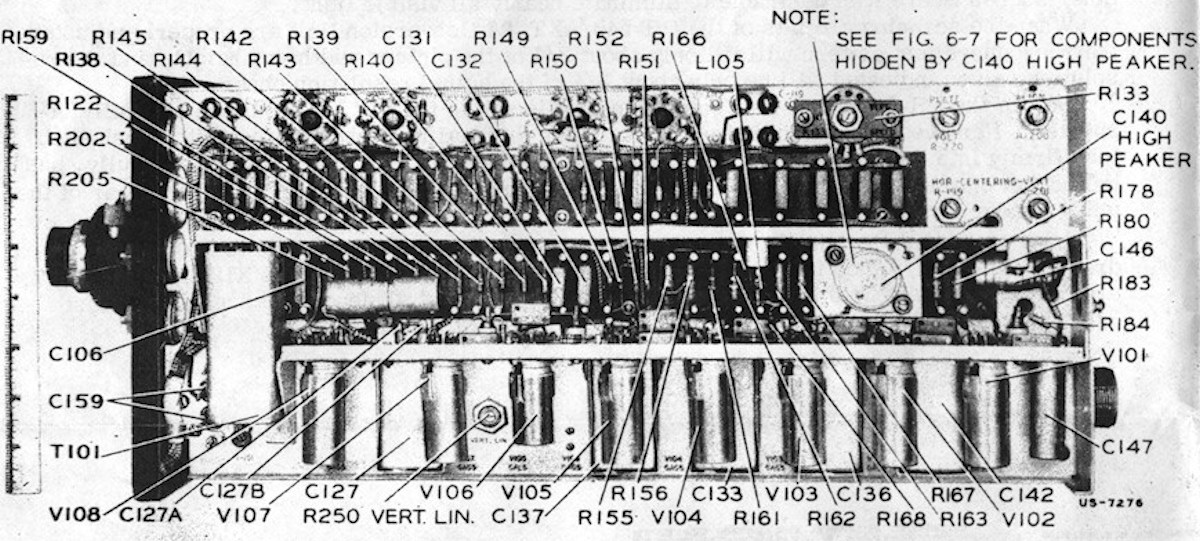
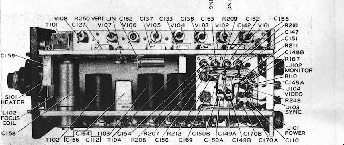
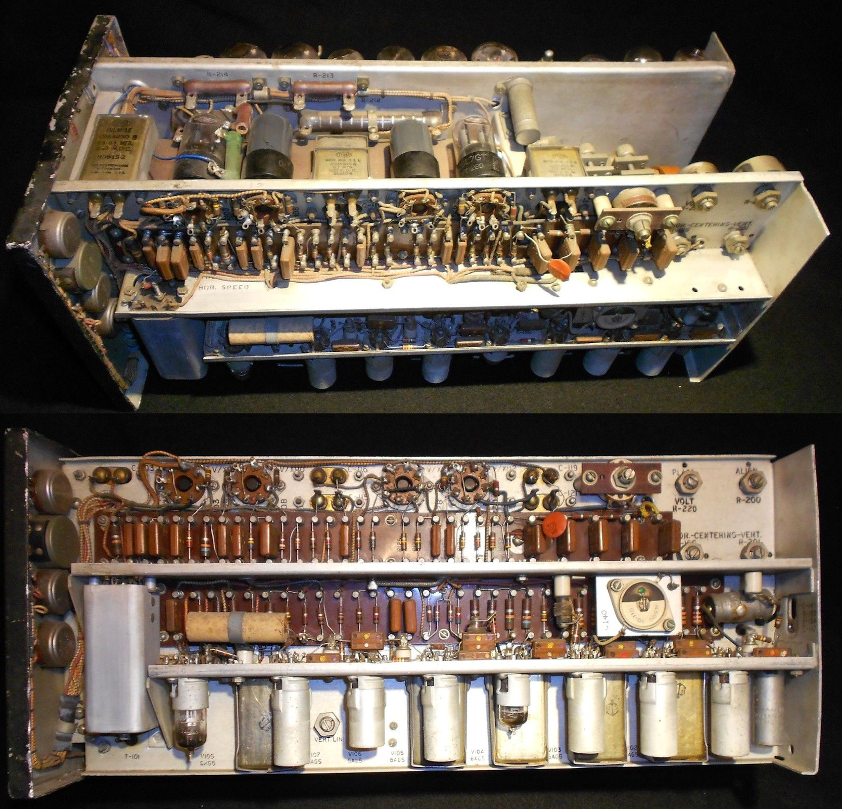
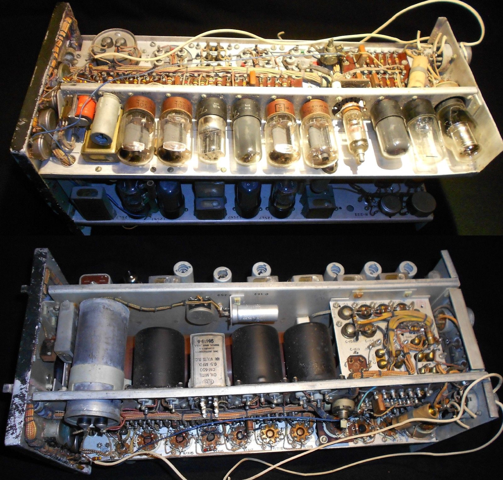
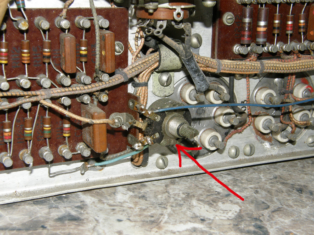
Component locations within the PH548/AXT-2A - 20151013 These photo diagrams will be necessary to locate the points I need to probe for continuity. Each contact, on each potentiometer will be traced back to its proper electrical net. Every circuit that was modified and then de-modified must be verified. If you are familiar with [my other military iconoscope TV camera restoration], you will recall the dense assembly of that camera. The wiring harness had been dressed on top of the passive components on the terminal boards. Many of these terminal boards faced inside the unit and could not be directly inspected or serviced. It was very difficult to trace or to locate a specific component. That was taken into consideration when this version of the camera was produced. In this design, RCA excelled at creating a logical, seviceable layout. 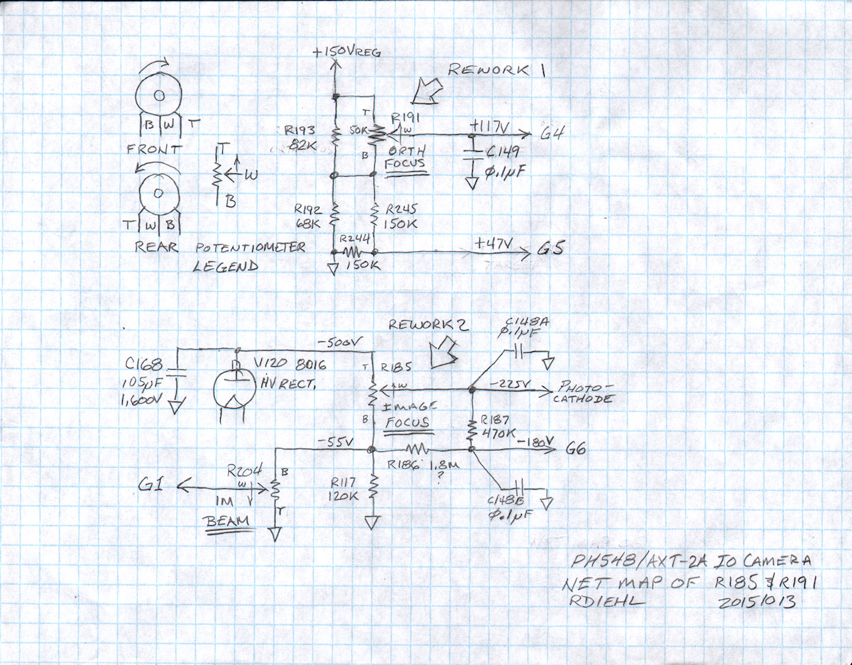
Scratch schematic of the business at hand - 20151013 Looking at the above schematic, it is now very easy to see where I need to probe, or buzz in the jargon of the trade. Traditional continuity testers had a small buzzer, beeper or bell in them. When you find the ends of the same wire, the tracer would begin to emit sound. Thus, the term beeping or buzzing to indicate continuity. The top and bottom contacts of R191 were disconnected. So, I will beep from R191-T to one end of fixed resistor R192. I will do the same for the bottom of R191-B, which also connects to the opposite end of R193. Same routine for R185. How convenient is it that R185-T is accessable at the cap on vacuum tube V120? The other end of R185 can be probed at R117, R186, R203 or even R204-B. Easy peasy. Potential errors and the mystery hanging wire (see previous video) will be corrected then. When I speak of potentiometers, I will refer to the top, bottom or wiper. Top refers to the clock-wise-most contact when the pot is viewed from the front. Bottom is the terminal that is most counter clockwise when viewed from the front. Wiper is self explanitory. Note the arrow on the schematic symbols for the pots. It always points to the top terminal. Top and bottom may also be referred to as high-side and low-side. 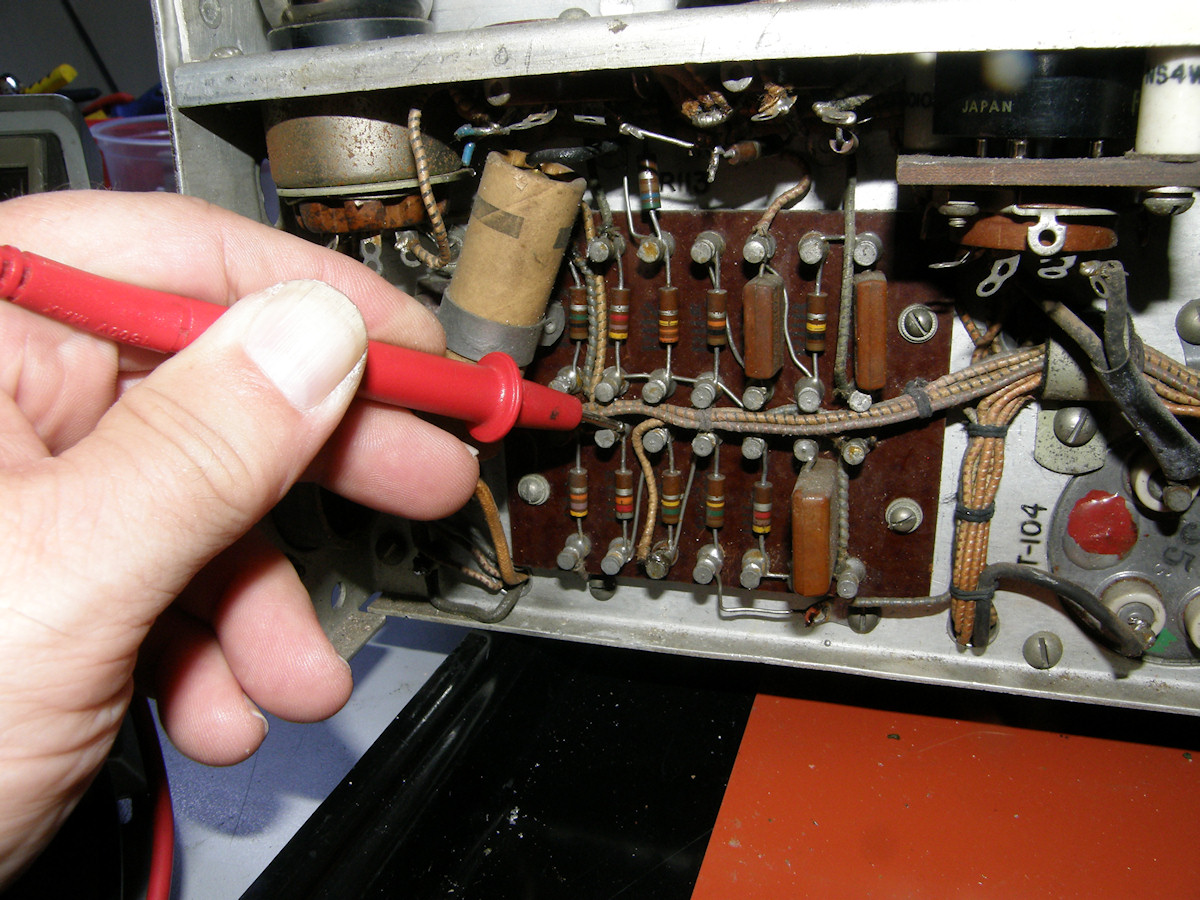
All rework undone and verified - 20151014 I had the time this evening to buzz the wires going to pots R191 and R185. R191 was perfect. R181 was not quite perfect. Examining the circuit closely, I realized the bottom terminal of R185 had to have two wires attached. One wire routed around the front panel to join R204 bottom terminal and one wire going back to R186 and R117 on the main chassis. The dangling wire, shown in the previous video, was the one that goes to the high voltage rectifier tube cap and C168 only. This is now properly reattached to R185 top and the other two wires are properly attached to R185 bottom. Next phase, resistance measurements of the power supply input pins of the power connector. Woo hoo! 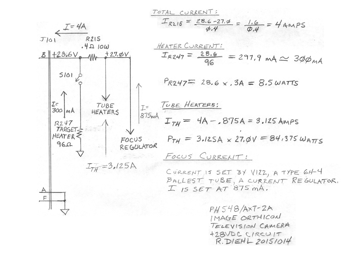
+28 Volt primary current flow paths - 20151017 The above diagram demonstrates the three primary current paths involved in the +28 volts circuit. (Based upon the voltage and resistance values printed on the schematic. Reality is a bit a different... Still a good starting point.) The three main currents are; The target heater circuit, the focus and centering circuits and the tube heater circuits. Some low voltage bias is taken from here also. But, it uses millamps where these three paths use multiple amps or major portions thereof. The target heater draws 1/3 of an amp. The focus coil circuit takes 875 milliamps (0.875 Amps) and remainder is consumed in the tube heaters at 3 and 1/8 amps. Dusting off my +28 volt, 5 amp power supply and my voltage and current monitor meter, we are ready to test the low voltage circuits in the image orthicon camera. Let's get on with it right now! 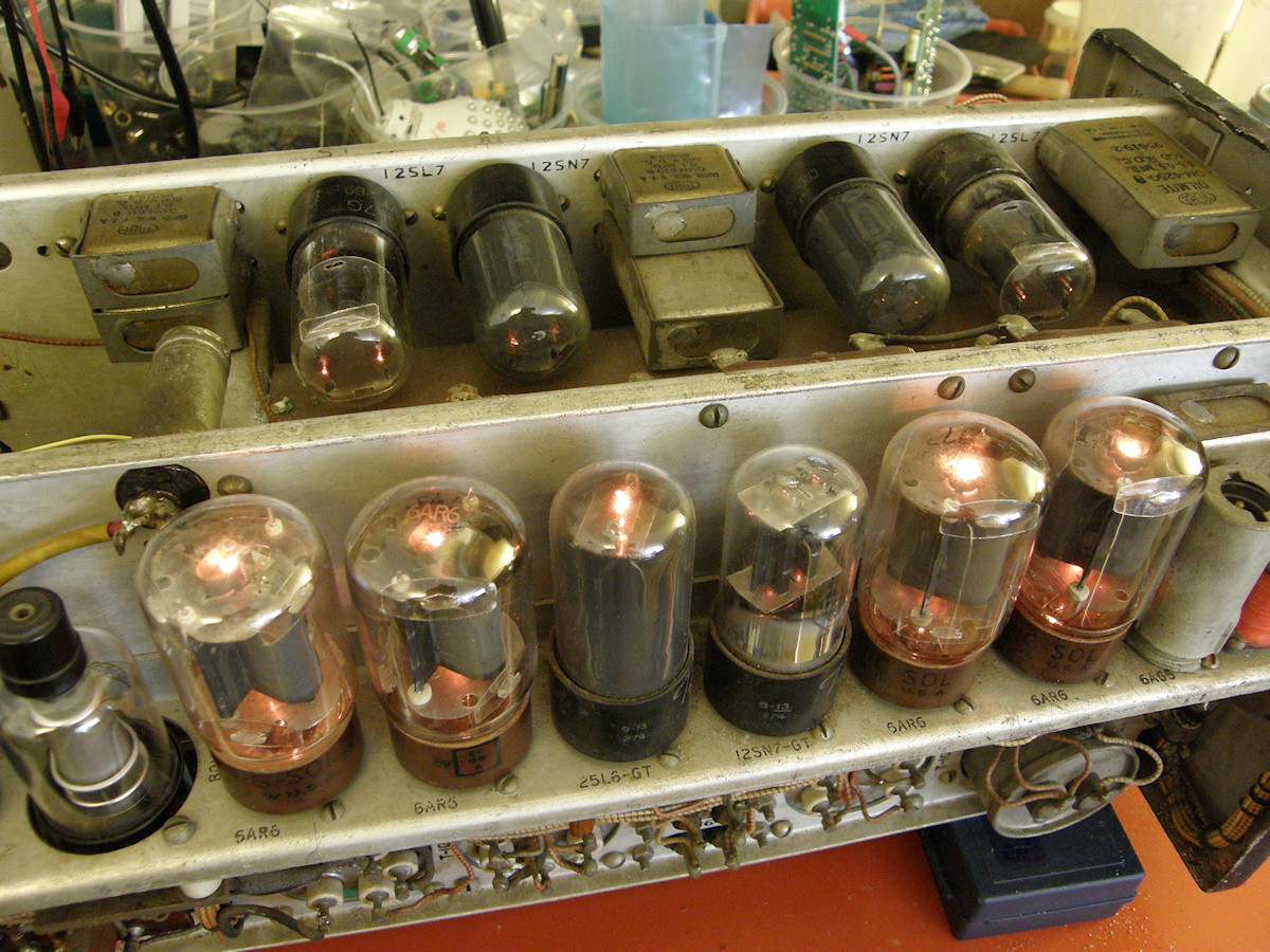
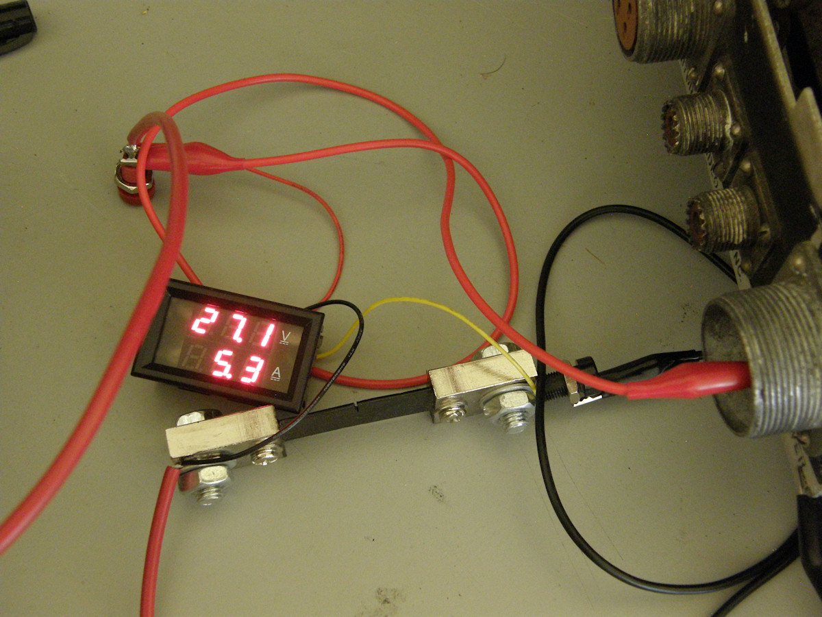
Good news and very bad news - 20151017 Good news everyone! The tube heater strings are working. Near as I can tell, all tubes are lighting. There are no high voltages applied to the camera at this point. Only the +28 volt supply. The meter indicates that the current is higher than expected and the power supply voltage is sagging appropriately. Note the size of the 100 Amp ammeter shunt resistor in the ground circuit. We are gonna need a bigger power supply. Bad news everyone. We have an open focus coil. This is a potential show stopper. The focus coil is in series with the centering controls and the notorious alignment coil. It is possible that when the wires shorted on the alignment coil, it burned out the focus coil like a gosh darned fuse. Looking very closely, we also discover a large amount of corroded copper. NO!!! Sadly, yes. It looks like Labguy now gets to figure out how to get the entire deflection coil assembly out of this camera to repair or rebuild it! Will Labguy fix the focus coil? Will this rusty darned thing ever work again? And what about Naomi? If you have made it this far, seek professional help.... er, um, I mean... check out [PH-548/AXT-2A Restoration part two]! Same Lab time! Same Lab guy! Same Lab channel! REFERENCES: 1. PDF [Denson Electronics Flyers #774 and #792]. Documentation for the PHX548/AXT-2A military image orthicon camera. Produced by Al Denson in 1974. Denson Electronics was a surplus store located in Rockville, Connecticut in the 1960s and 70s. Denson specialized in surplus and new television equipment of every variety known. When I built my first vidicon cameras in the 70s, Al Denson was gracious and answered every single one of my letters and made me great deals on the parts I needed. 2. PDF [1945 RCA 2P21 Image Orthicon Tube] 3. PDF [1953 RCA 5820 Image Orthicon Tube] 4. PDF [1954 RCA 2P22 'MIMO' Miniature Image Orthicon Tube] 5. PDF [ 940C Series high voltage capacitors] 6. PDF [ Amperite ballast tubes] Old school constant current regulators RELATED LINKS AND RESOURCES:
BIBLIOGRAPHY:
[HOME] [ELECTRONICS PROJECTS] [PART 2] Created: August 13, 2015 Last updated: October 17, 2015 |