|
LabGuy's World: 'Tiny Ike' - Iconoscope TV Camera Project
PART THREE - SYNC GENERATOR. Master timing for the video camera. 
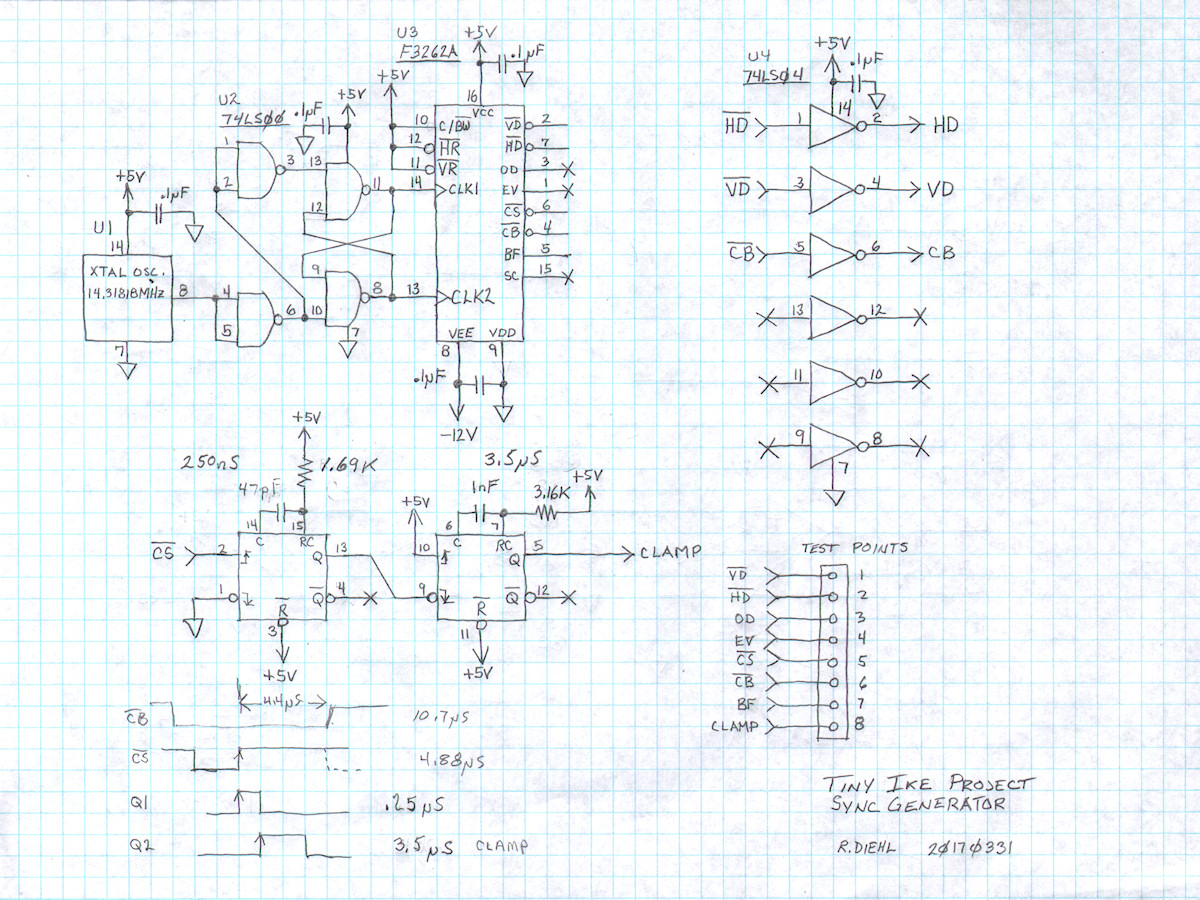
Complete Tiny Ike Sync Generator 20170314 Imagine a symphony orchestra. The musiscians are kept synchronized by the conductor and his baton. The sync generator performs the same function in a television camera. That is to start the line and frame scans on time, blank the electron beam during retrace, provide a reference pulse for DC restoration and add sync pulses to the video output video signal. FYI: Fairchild [3262A Data Sheet] in PDF format The Tiny Ike sync generator is constructed around the Fairchild F3262A from the early 1980s. It is a complete EIA (B/W) and NTSC (Color) sync generator on a single chip. I am operating the chip in color mode, without color bursts, because the 2.0475MHz crystal is apparently made of unobtainium. The output signal from this camera will be identical to the Y signal of an NTSC component (Y, U, V or Y, R-Y, B-Y) video signal, sans chroma components. For this mode, pin 10 (C/BW) of the F3262A is pulled to a logic high (+5V). There is one critical pulse the camera requires that the F3262A does not generate. This is the CLAMP pulse, created by way of the two timers in the schematic above (74HC221 not labeled). The CLAMP pulse activates the FET switch that grounds the back side of the video coupling capacitor that sits between the video preamp and the output video processor sections. That process will be described in greater detail later in this article. The timing process starts with a 14.31818Mhz oscillator (4 times the color subcarrier frquency of 3.579545MHz or 910 times the horizontal scannning rate of 15.73425KHz). Internal counters and decoders create all of the common pulses used in twentieth century American television. These are as follows: 
Fairchild F3262A Sync Generator Block Diagram Remember learning factoring in high school algebra? Here is a practical demonstration of that in the real world. The 14.31818MHz clock (4SC) is divided by 7, down to 130H, and then divided again by 65 to produce 31.5KHz (2H), which is necessary for creating the 2:1 interlace timing. The 2H is further divided by two to generate horizontal sync. 2H is also divided by 525 to generate vertical sync. In one field, vertical sync is in phase with horizontal sync. On the next field, vertical sync starts in the middle of the line. That is how the camera produces proper 2:1 interlaced scanning. Finally, relatively simple digital decoders extract the remaining pulses for the system. 
Complete F3262A Sync Generator Circuit (Highlighted) Only four IC chips. From bottom to top, 14.31818MHz crystal oscillator, 74LS00 quad NAND gate, Fairchild F3262A sync generator, and 74LS04 hex inverter. The 74LS00 conditions the clock pulses for the sync generator chip. The 74LS04 contains six logic inverters to invert any generated pulse, if needed, for downstream circuitry. I chose the F3262A because of its small footprint, easily obtained crystal frequency and no need for computer programming. This circuit requires only two square inches of board space. All four devices are installed in machined pin IC sockets for ease of replacement. The oscillator, being much heavier than an IC is secured to the socket with a solid #22 gauge wire strap. With only four pins, it kept falling out of the socket when I would flip the board to make modifications! [HOME] [ELECTRONICS PROJECTS] [TINY IKE INDEX] [PART 4] |