LabGuy's World: - 5FPn CRT TESTING
A very straight forward test set up - 20160410 I have been fascinated by the 5FPn CRT since the 1970s. Back in the day, the 5FP7A was used as the deluxe tube for classic slow scan television. A TV system that sent one 120 line video frame every 8 seconds or so. But, because of the requirement for magnetic focus and deflection, I always felt inhibitted from trying to use this tube. Opting for the much simpler electrostatic oscilloscope tubes instead. The 5FP7A CRT was originally developed for airborne radar displays because of its compact size and extreme ruggedness. Today, the addtional technical requirements of this venerable CRT are just minor details to overcome. Ok. You got me. I also got very lucky and purchased an extremely rare and valuable antique CRT focusing magnet on Ebay. It was now possible for me to experiment successfully with 5FPn CRTs. No more excuses! The lower case letter "n", that appears in the title above, refers to the type of flourescent phosphor that is applied to the inside of the face of the tube. There are many types. Many phosphors are the same color in flourescence and phosphorescence. Some phosphors can have two colors. One color while being excited by the electron beam (flourescence) and a second color in its afterglow (phosphorescence). Phosphorescence time can be from nearly zero to many seconds or even minutes. CRT Phosphors have fascinated me since my youth. I'd like to share some of what I have learned with you. The following is a demonstration the technical operation of the 5FPn CRT as well as five different early CRT phosphors, as follows. The first tube is a 5FP5 with a blue short persistence phosphor. P5 phosphor was used for photographic high speed oscillography and television kinescope recording. P5 has a light blue hue. Number two is a 5FP7A with classic two stage blue/UV short and yellow long persistence phosphors stacked atop each other. P7 was developed for WWII analog radar systems. In some batches, the yellow component can appear more greenish. Third is a 5FP11A with a short persistance blue phosphor. Used in film recording and slow scan flying spot scanners. Very bright deep blue color. The fourth CRT in the line up is a 5FP12. P12 is an orange medium long persistence type. You may have seen it in 1980s vintage computer monochrome monitors and data terminals. Afterglow about 2 seconds. Finally, there is a 5FP25 with relatively modern medium persistence orange phosphor used with modern digital radars. 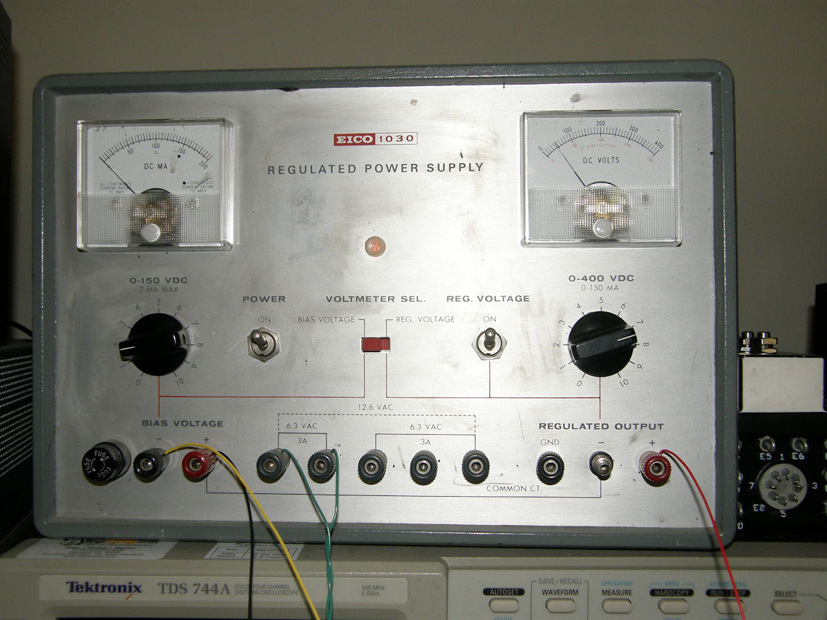
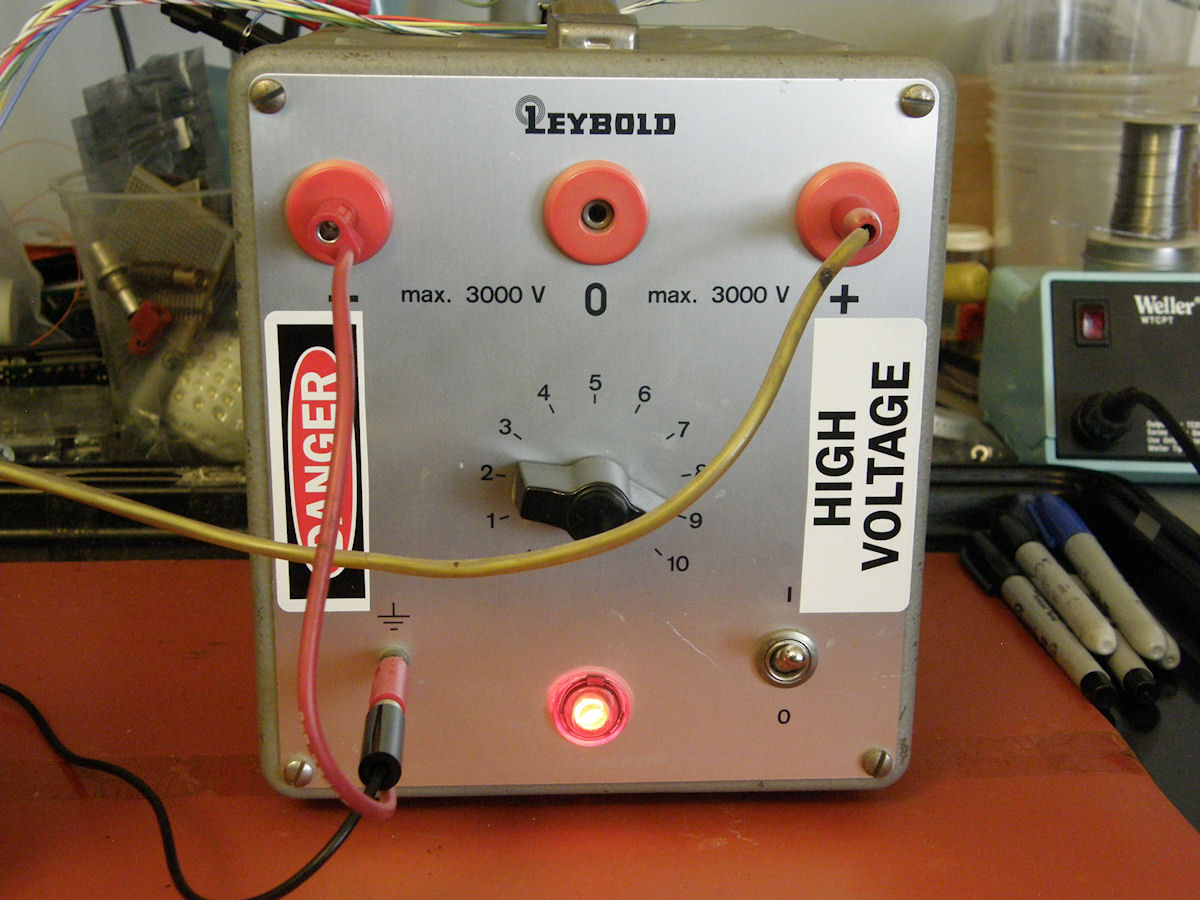
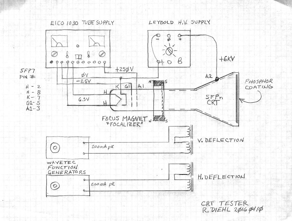
The necessary power supplies for the job - 20160410 The first step in bringing the 5FP to life is to apply the correct voltages and currents to the electron gun in the tube. I am using a classic Eico 1030 general purpose vacuum tube power supply. It has heater voltages at high current, negative DC bias down to -150 volts and B+ output of up to 400 volts and 150mA. This supply will drive the lower end of the electron gun. An additional high voltage supply is used for the second anode voltage. The Leybold high voltage supply is configured for zero to six kilovolts for this project. The experiments were performed with only about 5 KV applied on average. High voltage was adjusted slightly for each tube to accomodate best focusing of the spot. First 6.3 volts AC at 600 mA is applied to the cathode heater. This heater expends 3.6 watts of power. Next, we ground the cathode and apply a negative bias voltage of between zero and minus 40 volts or so to the first grid, called G1. This controls the electron beam intensity. Folowing G1 is G2/A1. This electrode is operated at plus two hundred fifty volts and its job is to accelerate the electrons, coming from the hot cathode, and send them toward the phosphor screen. On the way, the electron beam passes through the focalizer and deflection yoke, which we will discuss shortly. Passed the deflection zone is the second anode , also called A2. This is the carbon coating visible on the inside of the bulb end of the tube. Operating at 6,000 volts, A2 accelerates the now focused and deflected electrons toward the phosphor screen, which lights up where the electrons land. Let's get started. Shall we? 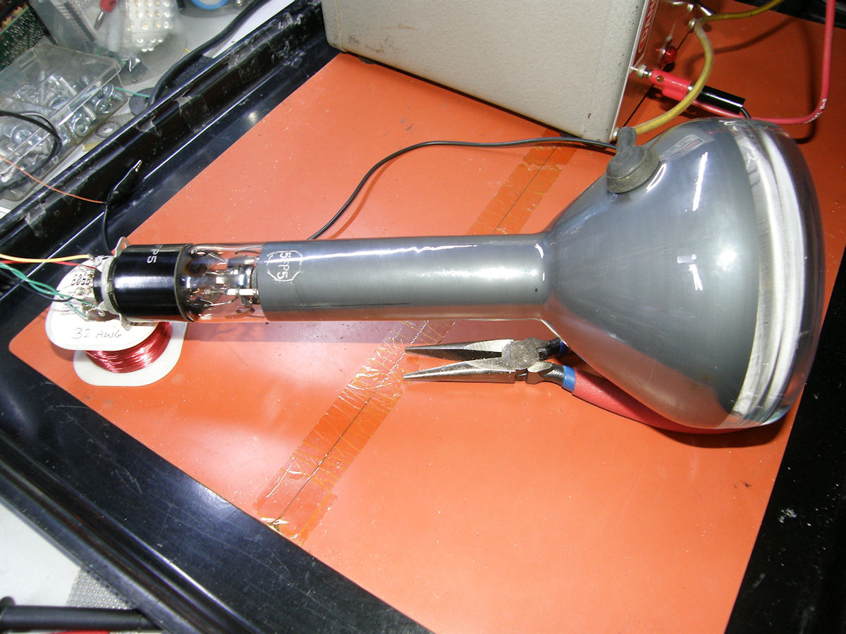
5FP5 gun only, no focus, no deflection - 20160410 In the photo, above, we see the 5FP5 wired for "electron gun only" operation. No focus, no deflection. 6 KV accelleration. We are seeing a magnified image of the top of the cathode being projected onto the phosphor screen. How is that possible? The aperture in G1 acts just like a [pinhole camera]. In this case, the 20 mil aperture (guessing wildly) is magnified to about two inches in diameter. A fine example of what lead Vladimir Zworykin to develop the electron microscope. That's all well and good. But we are going to need a way to focus the electron beam into a nice sharp spot on the screen. Maybe with some kind of magnet? 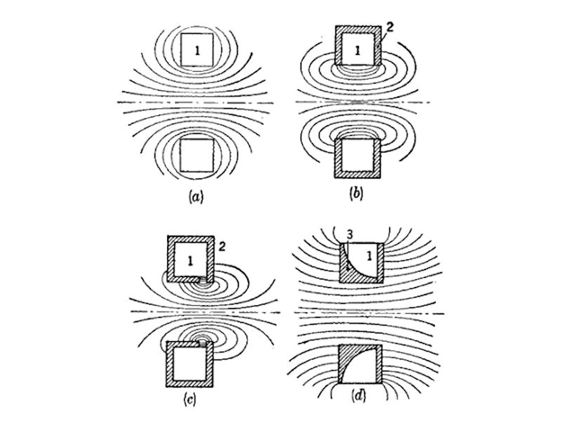
Various kinds of electrically powered focus coils - 20160423 The four illustrations above show various electrically powered CRT focus coil configurations. Figure (a) is just copper wire spun into a squared off ring or torus. Figure (b) adds a soft iron shell around the wire coil and open on the inside. It focuses more of the magnetic field into the neck of the CRT. Figure (c) shows the iron frame with the gap reduced to a small area, increasing the field strength yet again. In the last figure, (d), the coils of wire are shaped to produce a more uniform, almost collimating, gradient magnetic field for precision focusing. You can find the latter in modern CRT video projectors. Figure (c) produces a field shape most like the solution we will be using for this test. Detail 1 is where the copper windings are located, inside the soft iron shell, detail 2. The open gap, on the inside of the torus, produces a very concentrated magnetic field mostly in that region. But, being electrically powered, this magnet wastes energy and creates additional heat. Had we used an electromagnetic coil, it would have needed yet another power supply to operate that too. As it turns out, there is a better way. 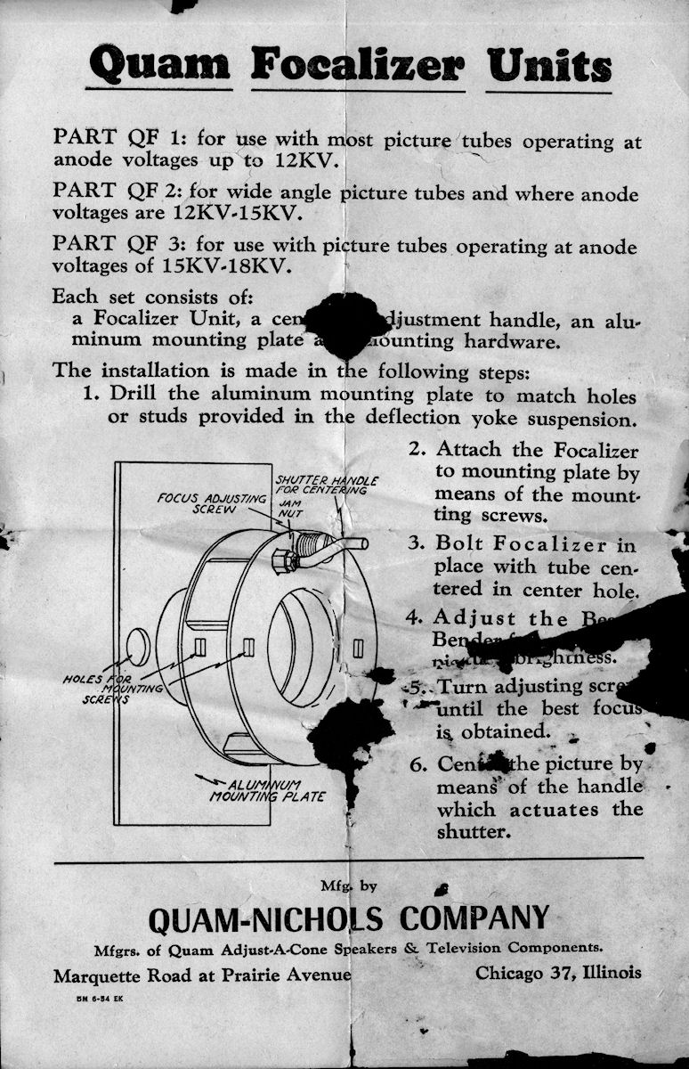
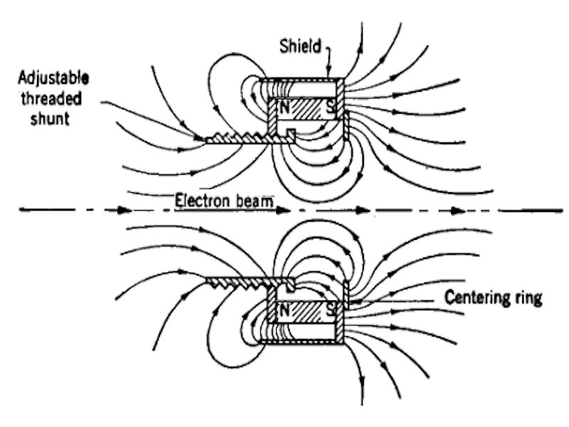
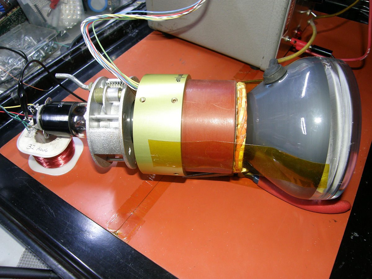
The Quam Focalizer Unit datasheet - 20160423 The device I am using is called a Quam Focalizer. It solves the power and heat issues by using powerful ALNICO (Aluminum, Nickel, Cobalt) magnets in place of electrical coils. A soft iron frame forms the magnetic field into a torus shape. The electron beam is passed though the "donut hole" of this field, where the magic takes place. Elegantly simple and reliable. The cut away view in the operational illustration shows how the focalizer works. The iron frame directs most of the field into the center of the CRT neck. The diverging electron beam passes through this region and is turned back inward on itself by the magnetic field so that it converges to a sharp point at the phosphor plane. The threaded shunt in the illustration is able to move and adjust the field strength for sharpest focus at the phosphor screen. 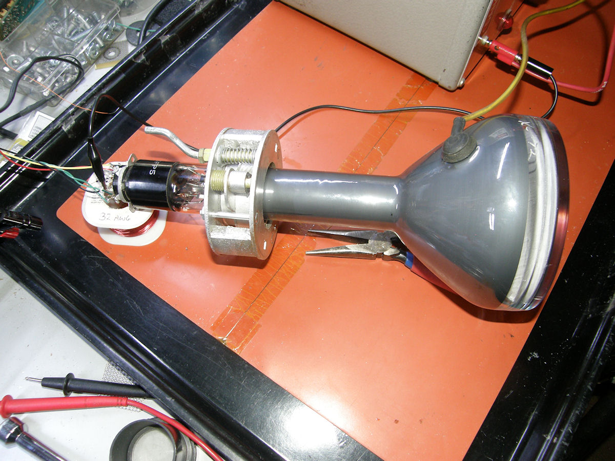
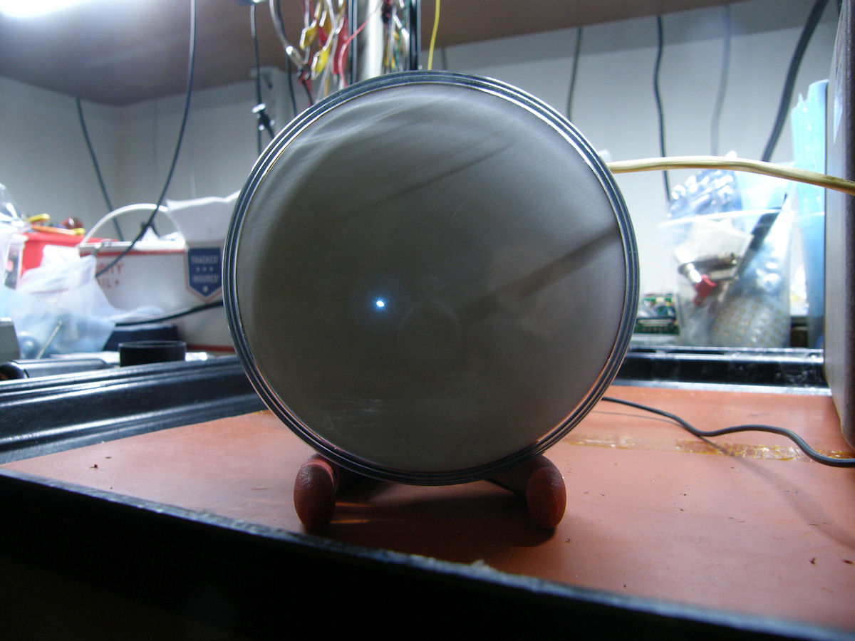
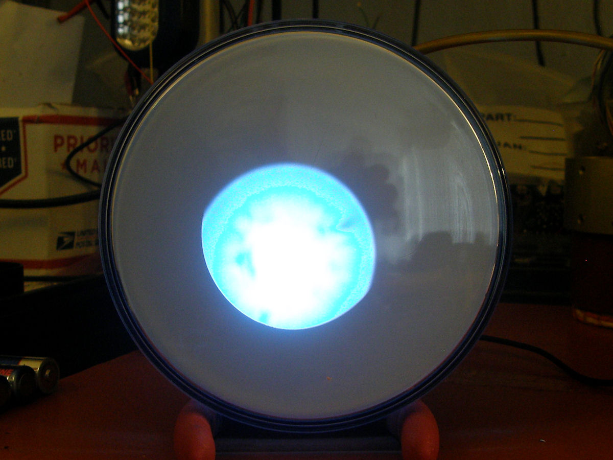
5FP5 gun only, permanent magnet focalizer in place, no deflection - 20160410 In the second test, we install the focalizer on the neck of the CRT and get a sharply focused spot on the screen. Success! Powerful permanent magnets form a field that bends the electrons in the same way a glass lens bends light. I moved the focalizer around a bit until I found the sweet spot or best focus. There is an adjustment on the focalizer for centering the spot. But, since it is not bolted down anyway, we can ignore that for now. It works just like magic! What else can we do with some more magnets and this CRT? Let's find out! 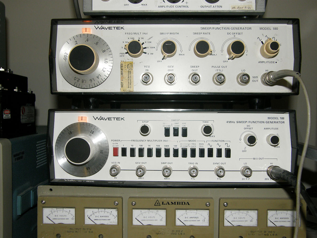
Adding a precision X & Y magnetic deflection yoke - 20160410 What good is a stationary spot on the face of the tube? Nothing, if we can't show some agression and push it around a bit. Am I right? For this, we use a magnetic deflection yoke. A pair of electromagnets positioned at 90 degrees to each other. One coil pushes the beam up and down (Y), the other coil pushes the beam left and right (X). The X & Y coils in this yoke are symetrical. That is to say they are identical in both axis. In a TV yoke, the coils are different and each is wound in way that is optimum for the fixed frequency at which it operates. The vertical (Y) coil runs at a low frequency of 60 Hz and the horizontal (X) coil operates at 15.75 KHZ. A difference of 525 times in the USA. This particular one was designed for a precision film printing machine that was used to transfer computer generated imagery (CGI) to actual 70mm movie film. That's how the movie gets out of the computer! In operation, it would print at a speed of about one frame per minute. If you want really fast deflection, this is not the CRT deflection yoke to use. For me, this yoke is perfect for an upcoming variable speed tv camera project. This end is of course the viewing screen. This yoke is also perfect for these experiments. Using a DC power supply, I determined that full deflection of the spot from the center of the screen to the edge of the screen takes about 200mA of DC current. The electrical resistance of the coils in each axis is 1.6 ohms. Nearly a dead short, which indicates that this is a current driven device. Surprisingly, my Wavetek function generators high level outputs are able to directly drive this yoke with very good results. The output is rated at 20Vpk/pk open load or 200mApk/pk in the current domain. Sweet! The scanning raster begins to shrink when the sine wave frequency surpasses two kilo Hertz. I recently constructed a dual 20 watt stereo audio amplifier kit just for this purpose. But, when I tried to drive this deflection coil with it, the results were simply putrid. The distortion was terrible. Apparently this amplifer could not deal with the near short circuit heavily inductive load. I removed the amplifier and used the Wavetek generators directly and this gave quite acceptable results.. 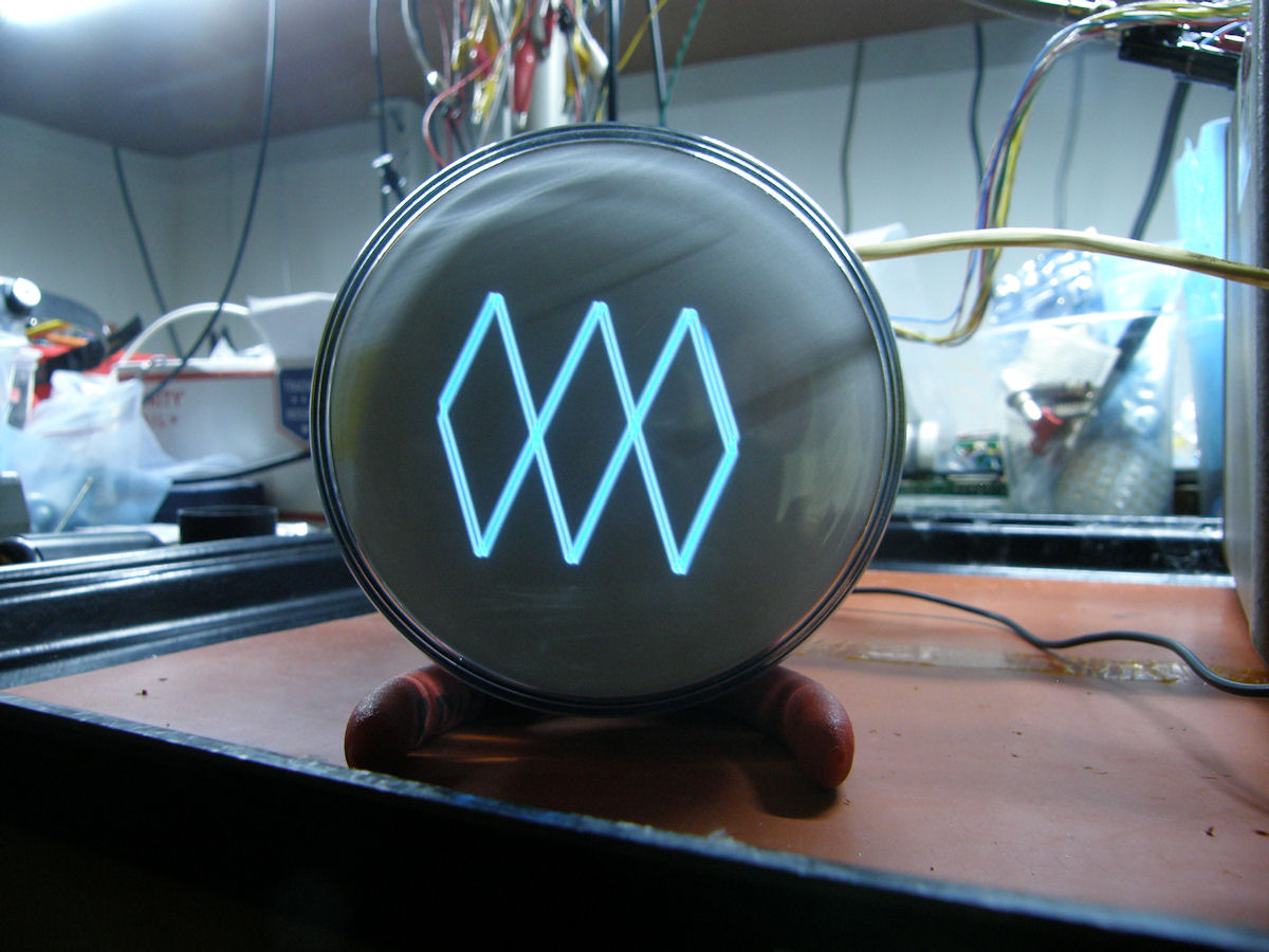
5FP5 in full operation. Blue short persistence photographic phosphor - 20160410 P5 CRT phosphor. Above, I am applying two triangle waves of about 3:1 frequency ratio to the two coils in the yoke. The frequencies are either less than one Hertz or a few dozen up to a couple hundred Hertz. (I did not specifically keep track of the exact frequencies. Just that they are "slow" in general.) Unfortunately, because of my digital camera's automatic exposure controls, the decay rate is not easily displayed here. P5 phosphor appears as a flying spot to the eye. 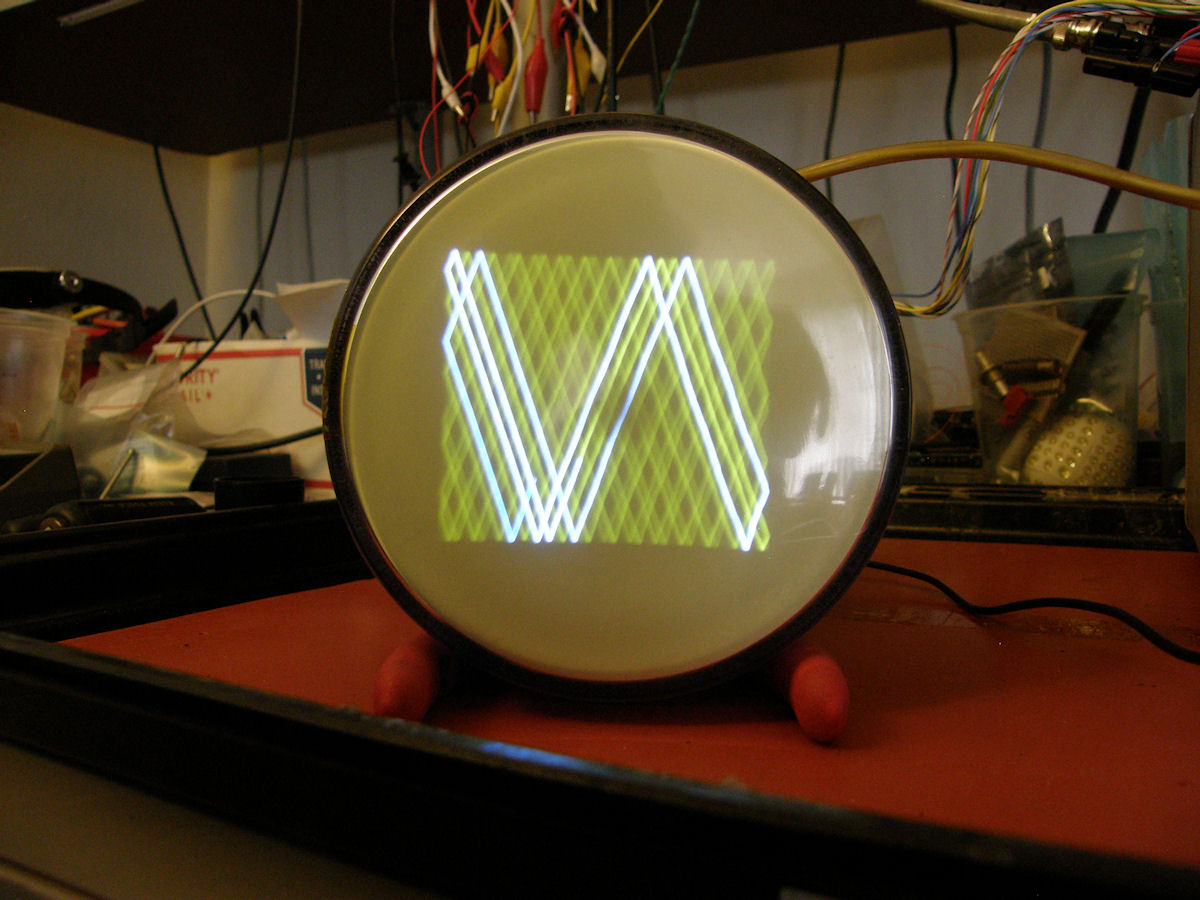
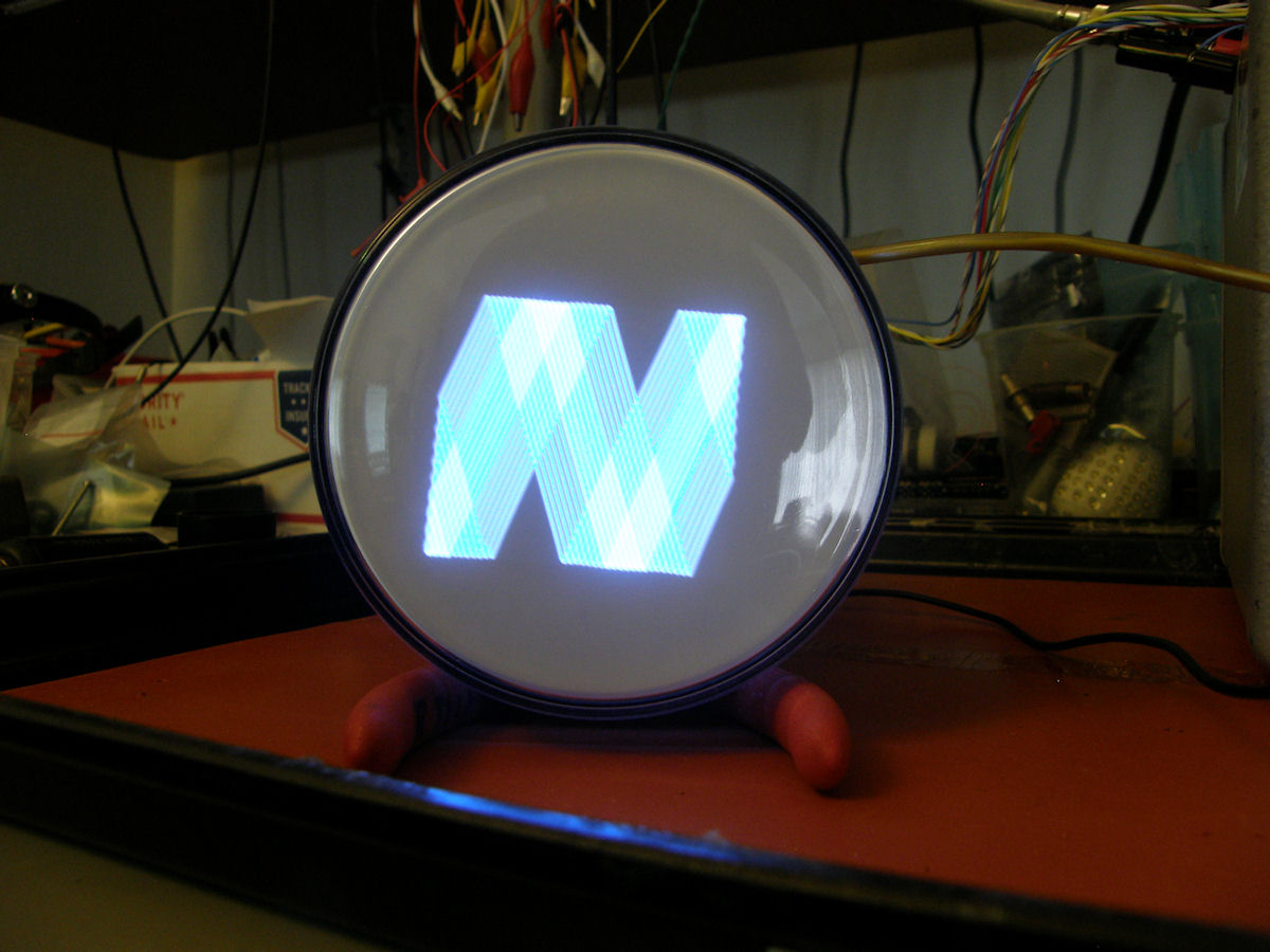
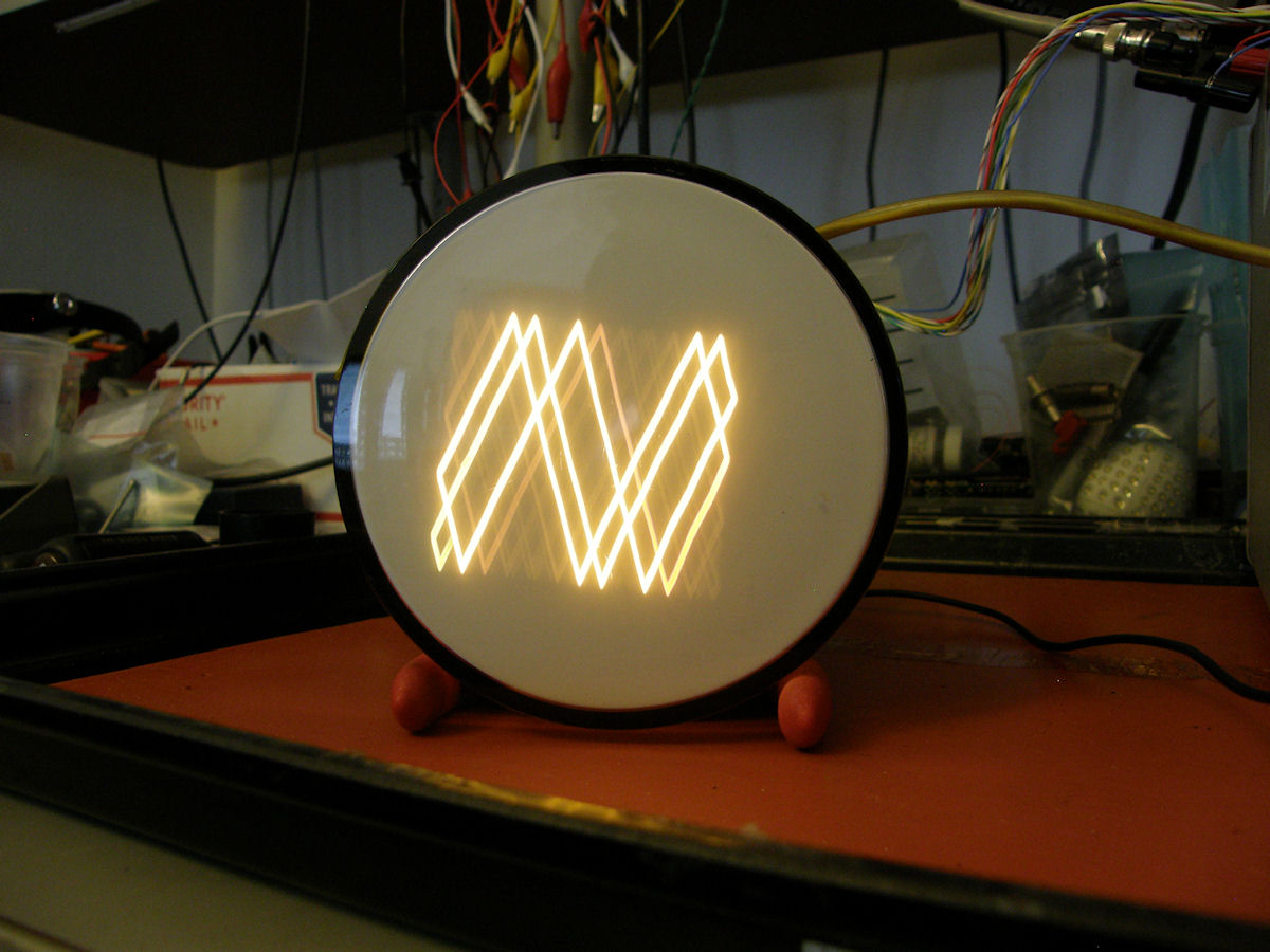
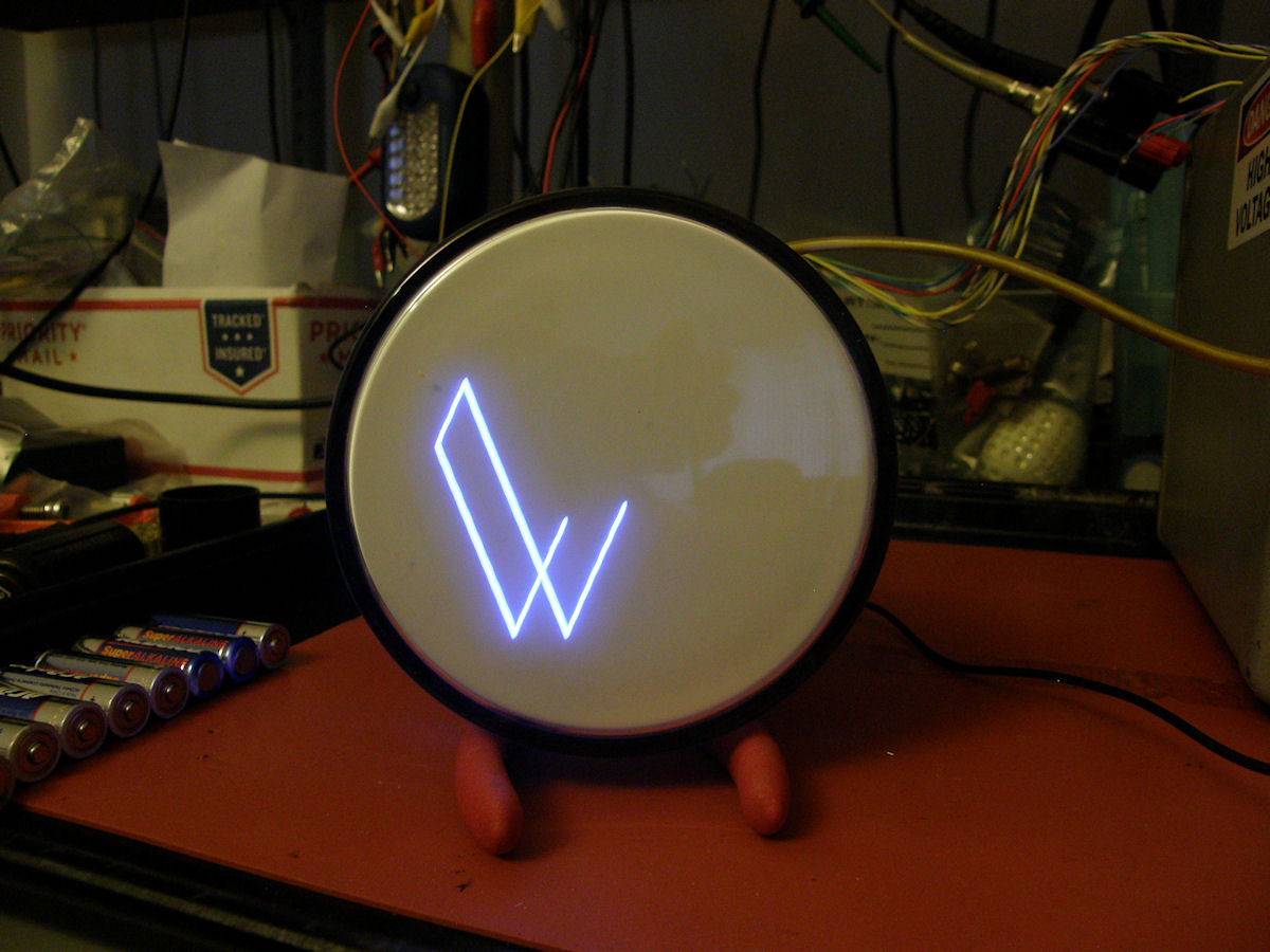
5FP7A in full operation. Blue short / Yellow long radar phosphor - 20160410 P7 CRT phosphor. A classic radar tube display. The part that looks bluish white is actually bright blue to the eye, when viewed through the glass at the back side of the phosphors. The blue phosphor also has a very strong ultraviolet component that stimulates the yellow to glow better than electrons alone. The afterglow can last up to 30 seconds in pitch black darkness. 5FP7A Demonstration video - 20160903 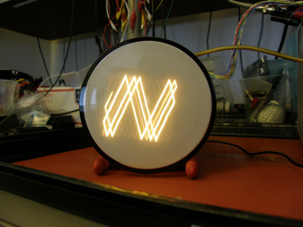
5FP25 in full operation. Orange medium persistence radar phosphor - 20160410 P25 CRT phosphor. A realtively modern radar tube display. This one does not glow as long as P7. It does work well with systems that have update rates in the two to three second range. 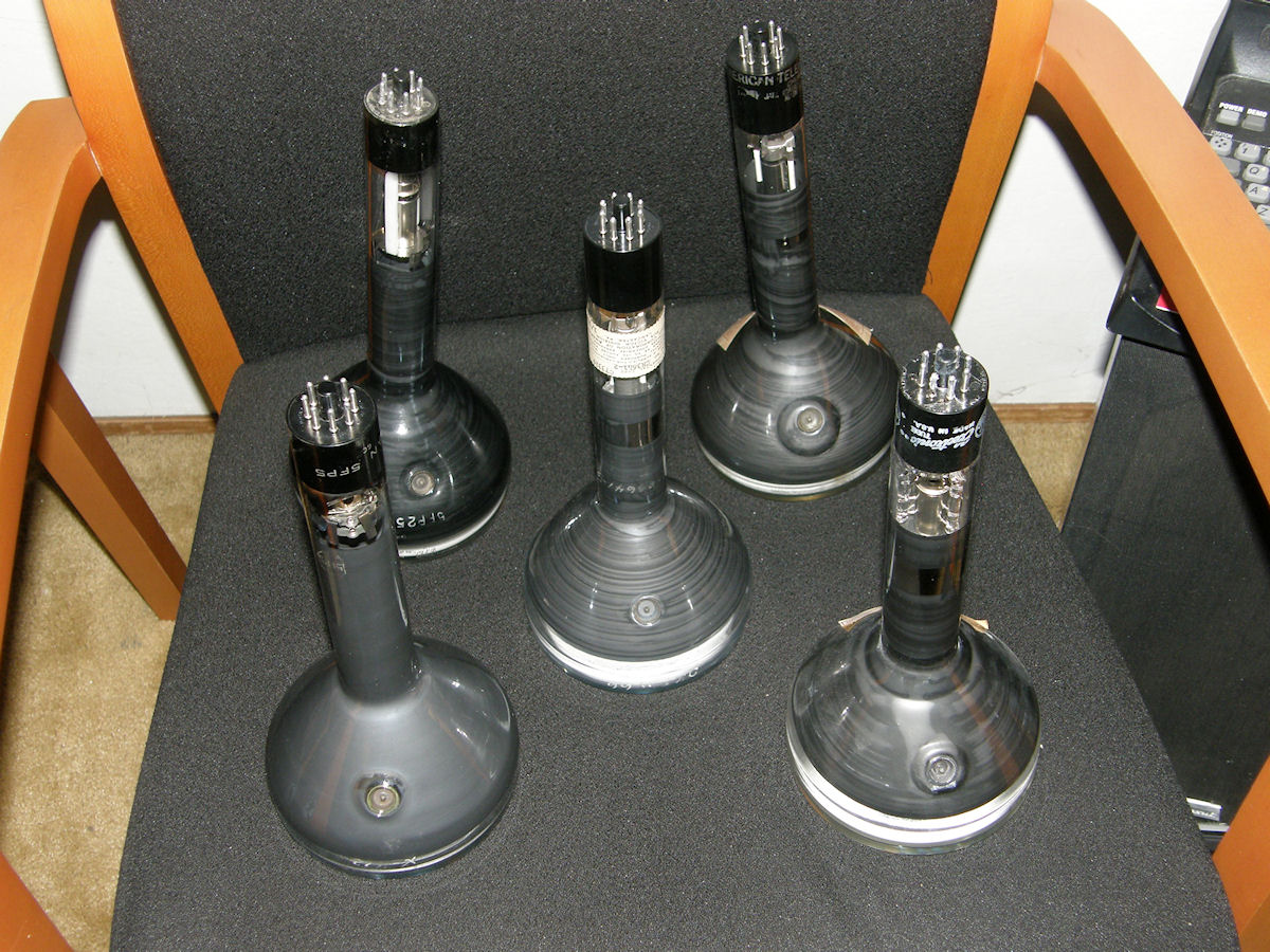
Five 5FPn cathode ray tubes. P5, P7, P11, P12 and P25. - 20160423 Purchased two more of these old CRTs through Ebay after writing about those first three (P5, P7, P25). I acquired a 5FP11A and an experimental RCA prototype 5FP12. Both boxed in the early 1950s until I opened them today. The 5FP12 is labeled as an experimental type C73319, serial number CR3641-2, dated 1/31/52. December first, 1952. That tube was in its box for over 64 years! You could say it's brand new and it seemed to work that way too. Say Labguy, that's a nice batch of old magic bottles you got there! 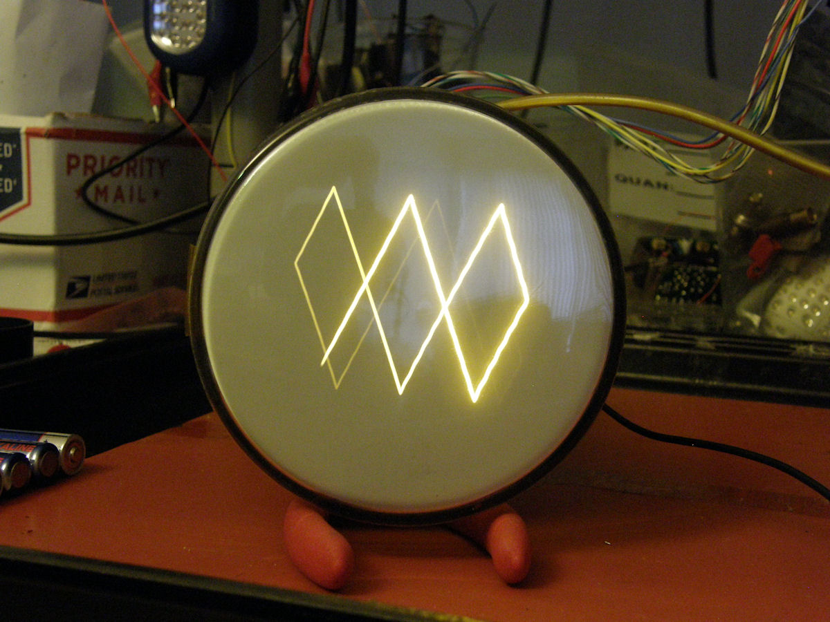
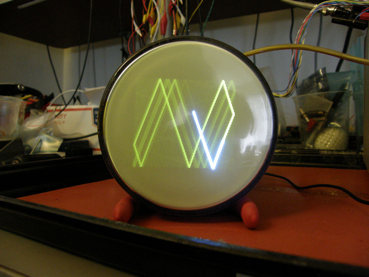
5FP12 orange medium long persistence and 5FP11 blue short persistence - 20160423 The P12 is a medium long persistence phosphor that was used in orange PC monitors and data terminals of the 1980s. The P11 is brighter and deeper blue than the P5 phosphor. Photographs can not convey the colors very well. Both tubes are being driven with triangle waves. Horizontal is about 1 cycle per second and the vertical is about 3 cycles per second. The afterglow of the P12 is very apparent. The length of the P11 blue trace is completely the result of the digital cameras shutter speed. This time the triangle waves were set to 30Hz for vertical and 10Hz horizontal. This is an on going project. Check back from time to time to see any progress. I am still looking for P1, P2, P4, P14, P15 and any other phosphor in a 5FPn. REFERENCES: 1. PDF [5FPn CRT General Specifications] 2. PDF [5FP4A television viewfinder CRT] 3. PDF [5FP7A five inch radar indicator CRT] 4. PDF [5FP14A five inch radar CRT] 5. PDF [5FP15A five inch flying spot scanner CRT] 5. PDF [Documentation on dozens of CRT phosphors] 6. PDF [Cathode Ray Tube Displays (C)1948 ] [HOME] [ELECTRONICS PROJECTS] Created: April 10, 2016 Last updated: September 3, 2016 |