LabGuy's World: The Composite Video Signal Review
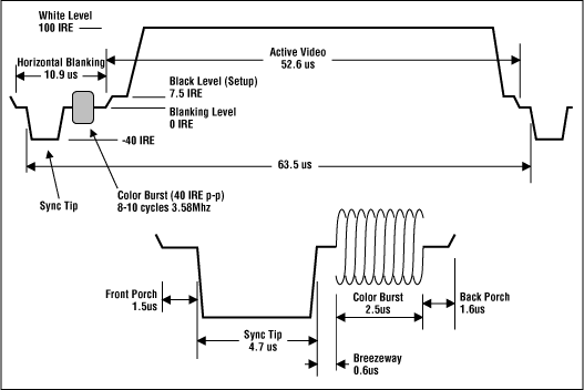
The general NTSC waveform and its attributes A video signal contains many kinds of information. There is sync information that tells the scan circuits of a monitor when to start a new line or field. There is the video portion that conveys brightness, as well as color, information. Another kind of information you can sometimes find in a video signal is closed captioning and or digital data that can be hitchhiking in the vertical blanking region of the TV signal. The video signal uses voltage to create an analog of the original light information at that point in space and time. The standard convention is that zero volts represents black and approximately plus point seven volts is peak white. (0V - 0.714V - more on that shortly) In the case of a color TV signal, there can be an RF carrier present on the video as well. I will not go into that as none of my circuits deal directly with the color signal at this time. Synchronizing information is represented by the pulses that go negative below the blanking level. This diagram only shows horiontal sync information. Vertical sync will be covered later when it becomes pertinent. Note the timing between the sync pulses and blanking intervals. I will show you circuits that are dependant on these numbers for specific sync funtions. DC restoration, for instance. Take note of the IRE levels on the diagram. An IRE unit is 1 volt, divided by one hundred forty. One IRE unit equals 714.3 millivolts. Sync extends from zero IRE, the video blanking level which is also zero volts DC, to -40 IRE units, or -0.286V. The video information goes from zero IRE to 100 IRE units, or 0.714V. Read more about [NTSC] and [PAL] video signals on Wikipedia. 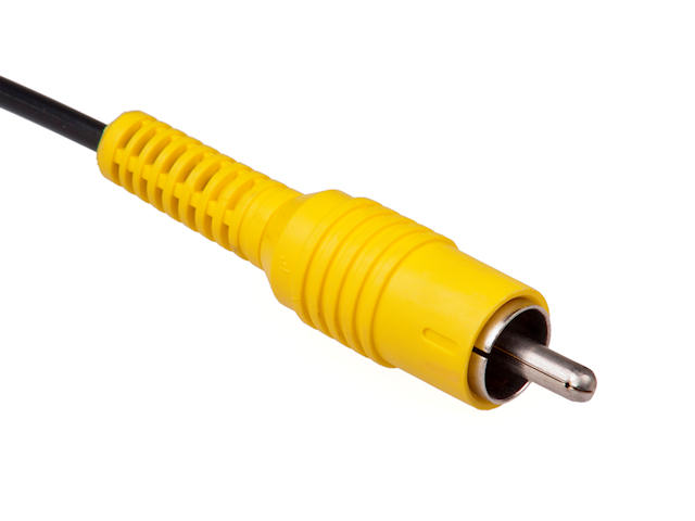
The yellow connector. Composite Video in and out. We all know and love this little fella. It is not the "yellow" signal as I have seen in discussion talking about commonent video. This is composite video. The signal that contains it all. Sync, video, chroma, closed captioning. Composite Video is of a specific voltage, and requires a specific working impedance for its distribution between video instruments. The spec is for a signal that is one volt peak to peak, terminated into 75 ohms. Well, golly Labguy! Exactly how do we deal with that strange requirement? 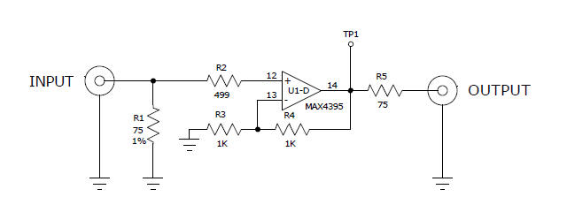
The classic video buffer amplifier This is the perfect place to start. Let's properly receive a composite video signal, amplify it, and send it back out with 75 ohms impedance. Imagine this amplifier driving itself. Note that this puts the output resistor R5 in series with R1, the input terminating resistor. This means that from the output of the amplifier, to the input of the next amplifier takes the form of a two to one voltage divider. To see one volt at the top of R1, the amplifier, U1D, must put out two volts at test point TP-1. And you can plainly see that the op amp circuit is configured in the standard gain of two configuration, giving us what we need. The Op Amp is the [MAX4395ESD, available at Digi-Key] and is made by Maxim Integrated. The data sheet is also available at that link. Please download that. We will be using this chip a lot. It is not the only part available for this job. An internet search for "video op amp" should turn up many more. Also note that the MAX439x family is available as a single op amp (SC-70 package) and as a dual op amp (SO8 package). This quad unit is in the SO14 package. 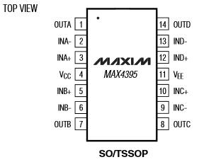
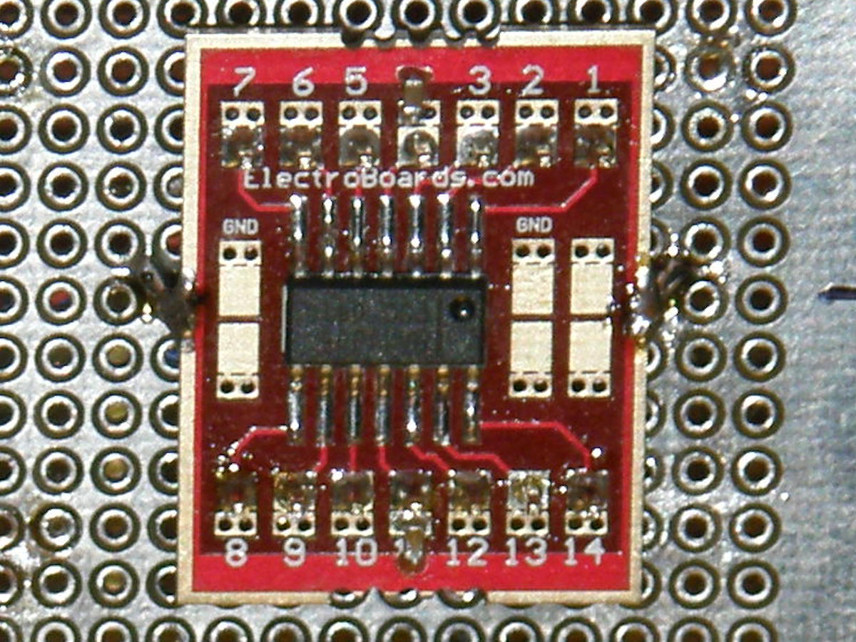
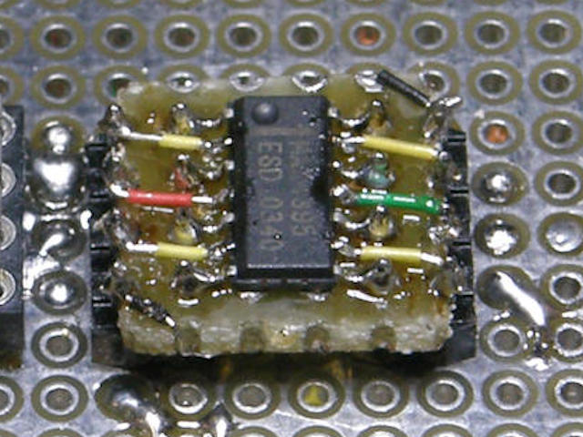
MAX4395ESD+ a quad video op amp and the chip mounted to various adapters. Mounted to an adapter board, this part makes four complete video amplifiers that take up just a little over one square inch of board space. Middle photo, near pins 4 and 11, you will see where I installed two 0.1uF surface mount capacitors. These are very important and must always be installed as close to the chip as possible. The third photo is an home made adapter, about half the size of the commercial board. The size reduction offsets the greater effort to build it. The pin spacing (pitch) is 50 mils (.65mm), or 20 to the inch, for "SO" (Small Outline) size ICs. To learn more about physical circuit construction, visit Labguy's [Hobby Electronics How To] page. The vector board I use has a grid of holes with a pitch of 100 mils or 1/10 of an inch. The adpaters make applying these surface mount parts a breeze. The red adapter boards, that I use frequently, are made by [ElectroBoards]. It is [model number SO14-50-EB]. [HOME] [VIDEO CIRCUITS COOK BOOK] Created: May 25, 2014 Last updated: May 26, 2014 |