|
LabGuy's World: - Part 2 1945 RCA PH-548/AXT-2A Image Orthicon Television Camera Restoration [HOME] [ELECTRONICS PROJECTS] [PART 1] 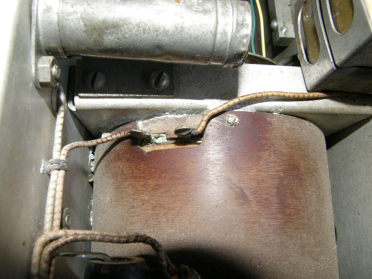
Good news and very bad news - 20151017 In part one, we made excellent progress. Then we discovered that image orthicon focus coil is open. Possibly burned out. Maybe rusted open. This is very bad. The current that passes through this coil generates a magnetic field that is absolutely critical to the operation of the image orthicon tube. This current supplies of the horizontal and vertical deflection centering currents as well. The big question is, can the focus coil be repaired? What's the plan, Labguy? How we gonna do this? - 20151017 I'm glad I asked! We are going to pull the focus coil out of the camera and service it as necessary. Why is there cold sweat dripping down my spine? Why is my lower lip quivering? Let's see what's involved in carrying out this insane plan... 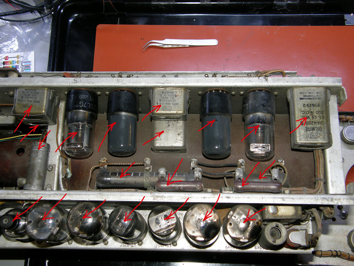
Alrighty then! All you gotta do is... remove all of these things first... - 20151017 After carefully staring at the camera for a while, it became apparent that the deflection yoke may come out of the top or possibly out the front. But, a lot of other parts are in the way. These must be removed or relocated before we can free the coils. 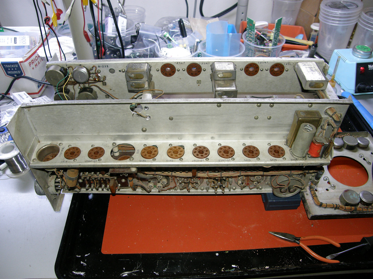
All the tubes are safely out and stored away - 20151017 In this view, all the tubes are pulled. C168 is out yet again. The five capacitors on the far chassis must be removed next. Followed by the power resistors, not visible, on the back side of the foreground panel. With the tubes out, it was a great time to give this chassis a cleaning with a dry soft bristle brush. Many years of grime were scrubbed off. Video: How I removed the focus coil from the camera (12:30) - 20151017 It is not particularly difficult. But, there are dozens of parts that must be removed to access the deflection yoke. Watch over my shoulder as the work procedes from start to finish. 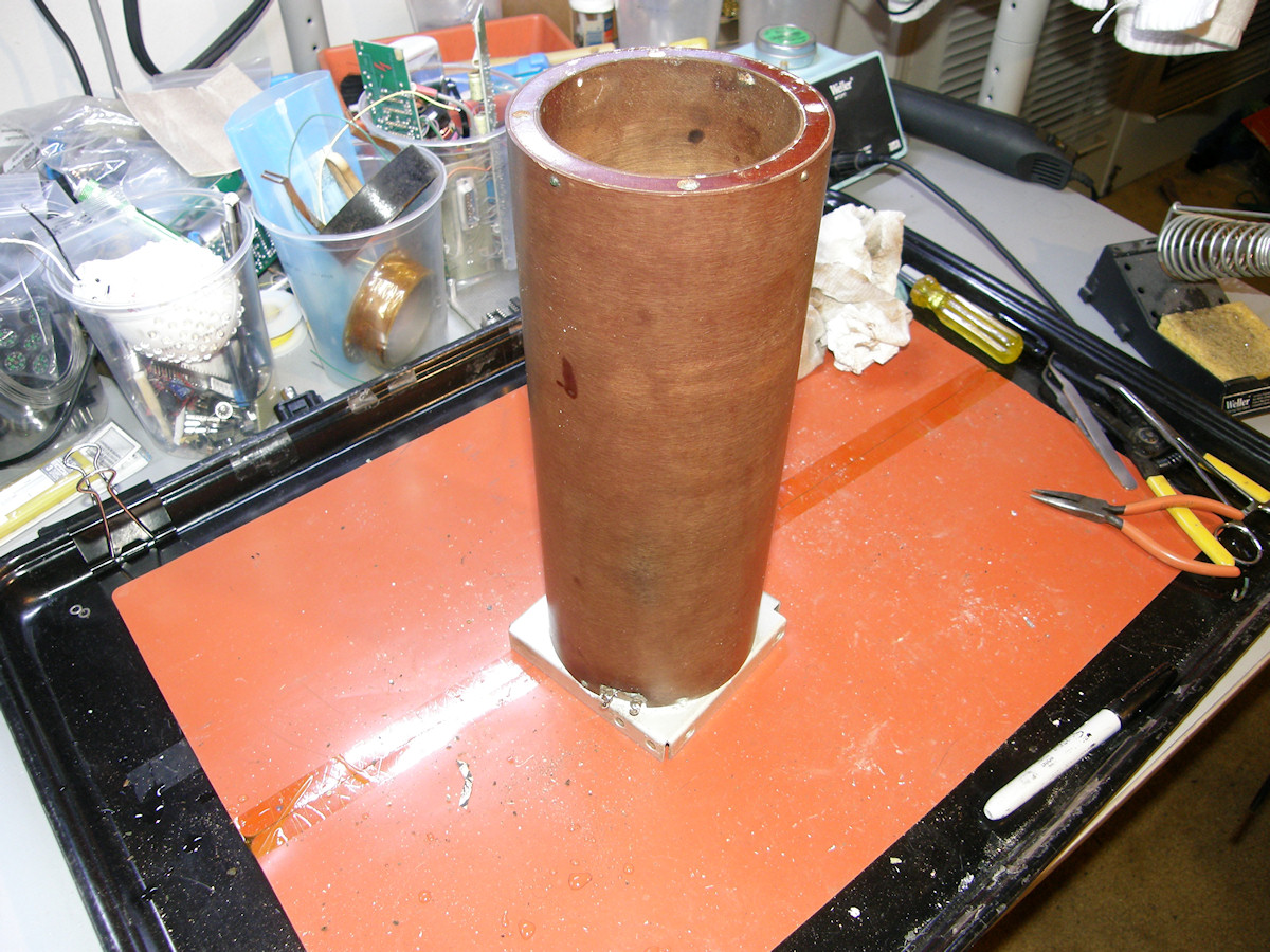
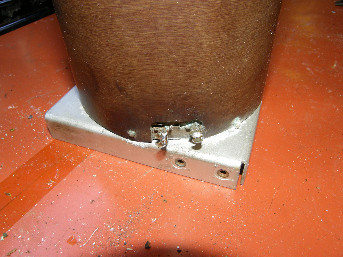
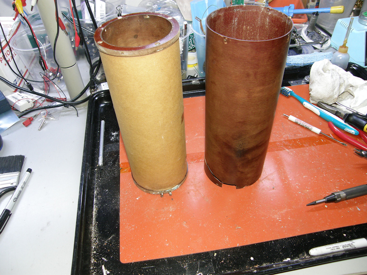
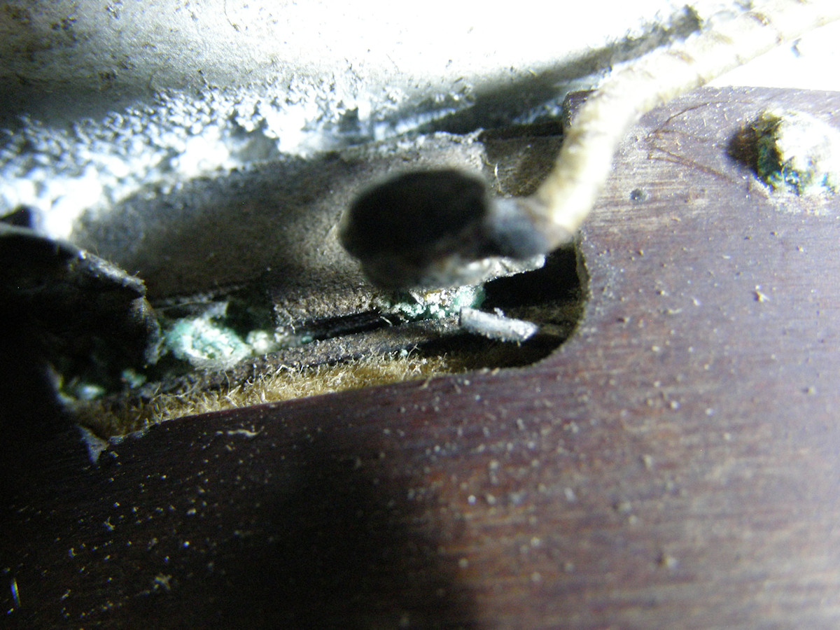
One big old roll of 18 gauge copper wire! - 20151018 My magic ohm meter tells me that the wire is broken at both ends. It appears that galvanic corrosion between the metal contacts and the copper wire caused the wire to fail right where it was soldered. This means I must unwrap the entire spool, trying to save the wire which is in great shape except at the very ends. Will be seeking a lathe to support the spool for rewinding. As soon as I opened the paper cover, needless to say, the copper wire lost tension and tried to fall off the spool. The scotch tape is my attempt to stop that. There is some good news however. The coil is not burned out. The bubbled spot on the outer casing is where a vacuum tube butts up agains it. What a relief! Corrosion is the big problem now. It has rotted the wires from the contact tabs. It has swollen the brass threaded inserts, that accept the mounting screws, and has split the composite material in several spots. The best way to fix it will be to unspool all of the wire, clean up the coil form, repairing all of the inset nuts and removal of metal oxides, and then rewrap the wire. That will be a great deal of labor for sure. Not an unattainable goal. Phew! Video: Deflection and focus coil commentary (04:00) - 20151017 This video expands upon the topic of the coils and my strategy for repair. But, it is my first good look at an image orthicon deflection yoke. I thought others would like that too. The soldered contacts on the back end go either to the horizontal and vertical deflection coil windings, but some of the contacts feed through to the socket contacts for the image section of the image orthicon tube. 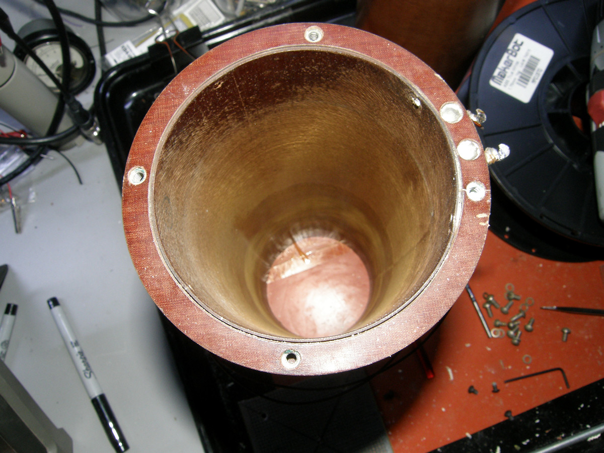
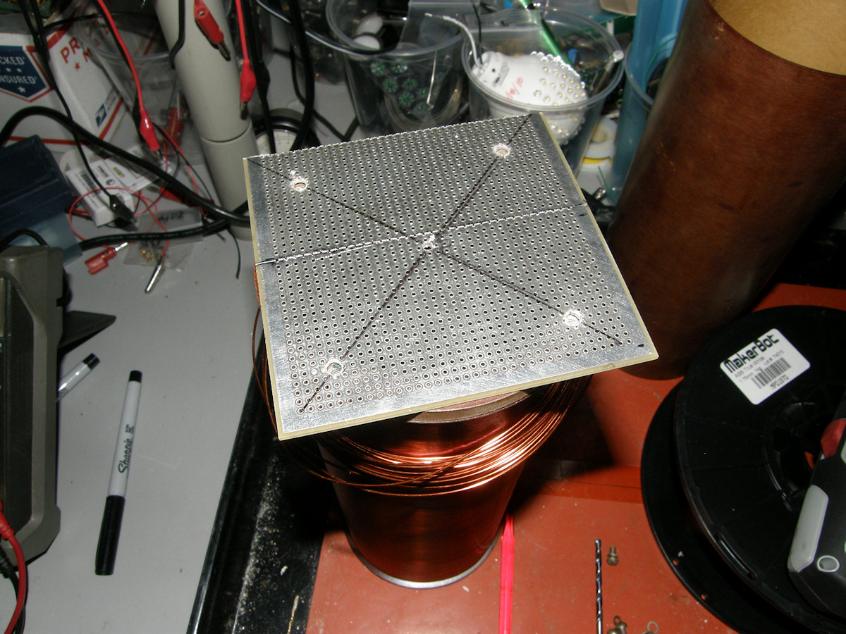
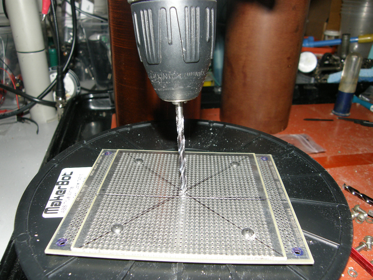
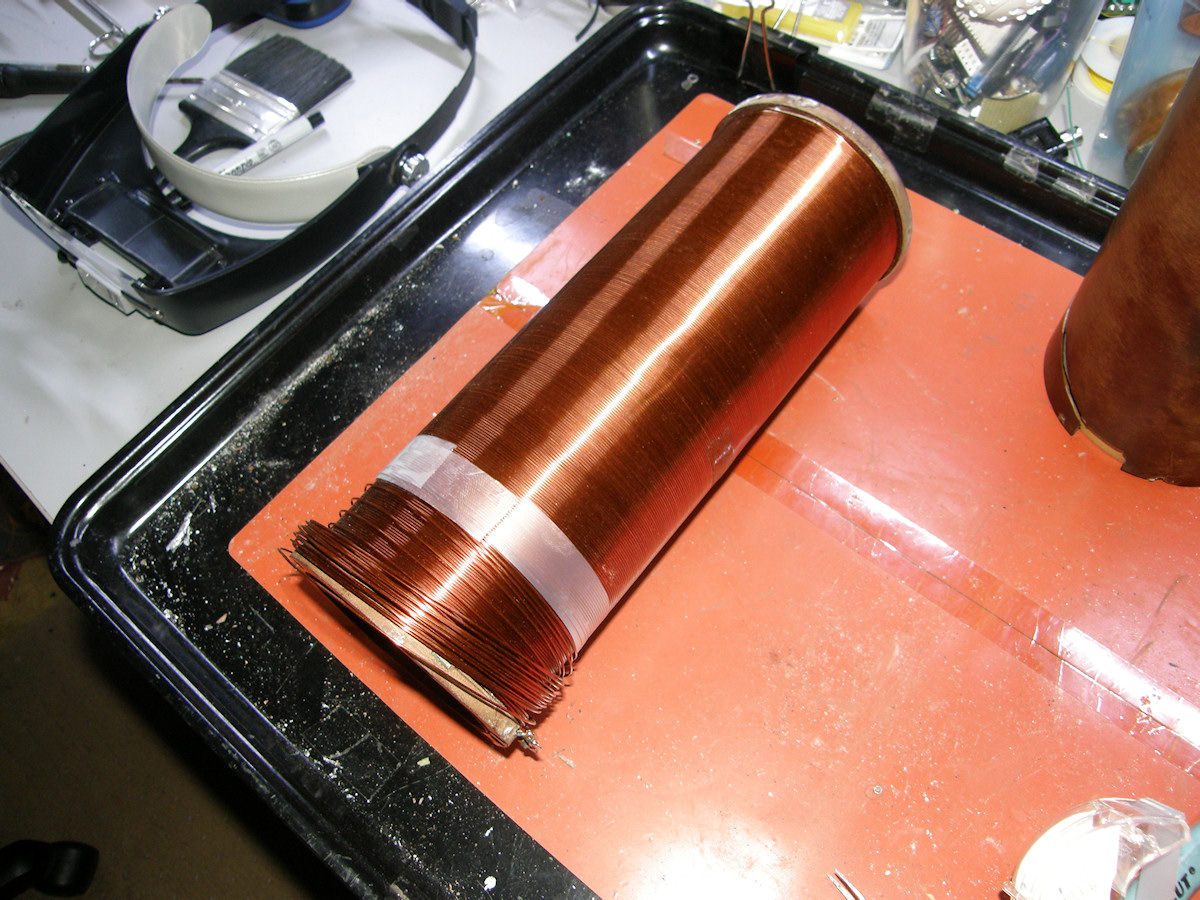
The rewinding process begins - 20151024 Starting at the focus coil, I needed to find a way to suspend it on an axle that would allow it to spin freely. Next would be a support box for the focus coil and a take up spool to temporarily store the wire. Do as little damage as possible means that the project moves very slowly to give me time to think up "that which is just right" for the job. While trying to figue out how to mount the focus coil, I had the epiphany to use copper circuit board material. Its incredibly strong, plentiful and cheap! Now I know why my third grade teacher was so adament about cutting out flat construction paper shapes that interlocked into 3D objects. Add threaded rod stock to this project and we can create a frame to support the coil and the reel. It was possible to clean the oxide corrosion out of the coil's embedded mounting nuts. I used stainless steel dental picks to do the fine work of digging rock hard oxide concretions from the screw threads. This allowed me to attach a flat plate to each end with 6-32 low profile hex head screws. Only one mounting hole was beyond repair, having the screw broken off within. Not a problem. By bolting the end plates together, I was able to perfectly align the center holes, which I drilled out to accept quarter inch threaded rod stock. The grid of perfectly spaced tenth inch holes is a built in measuring tool for locationg precise dirill points. The whole assembly now turns freely on its axle. May I introduce you to nerd wood? That is what I call blank fiberglass circuit boards. I am using suplus empty circuit boards like plywood. Quarter inch threaded steel rods bolt it all together. 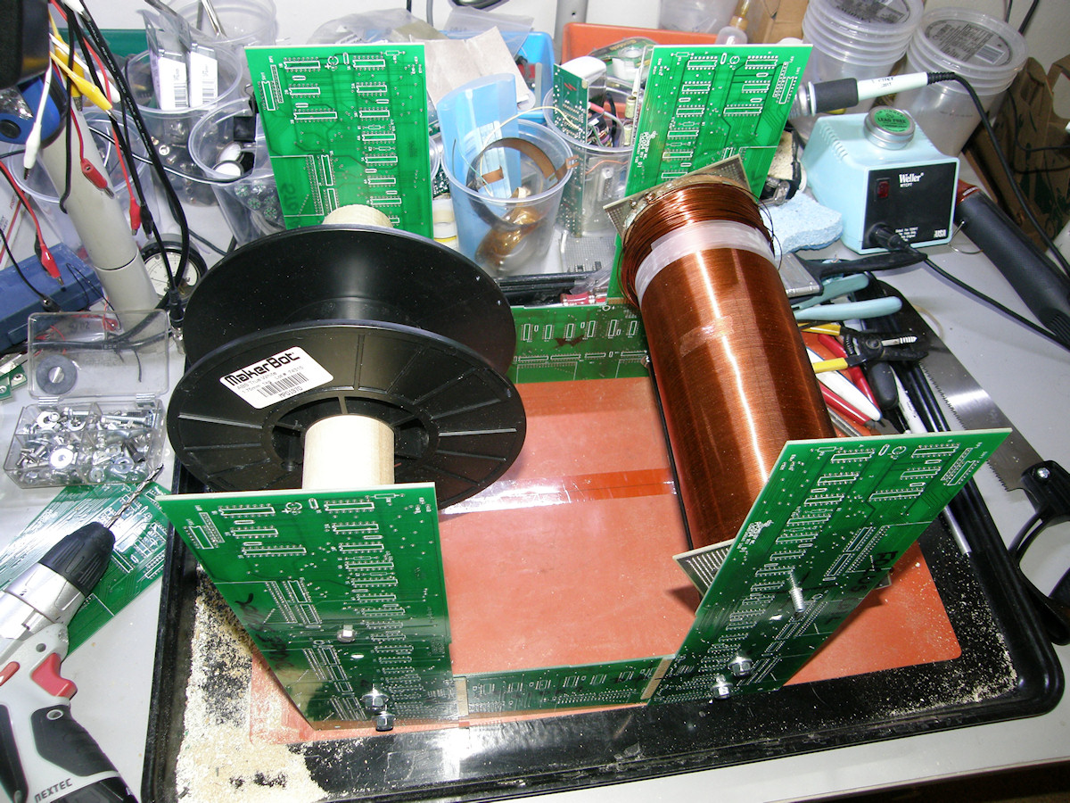
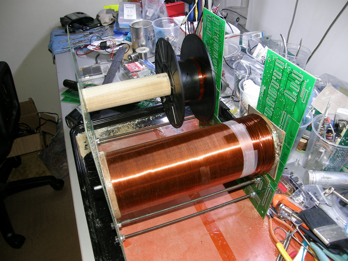
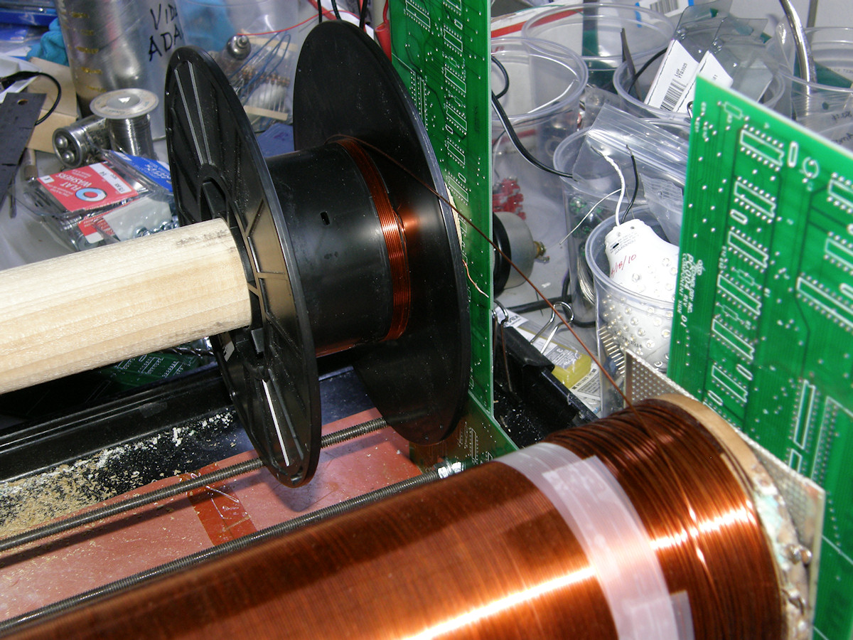
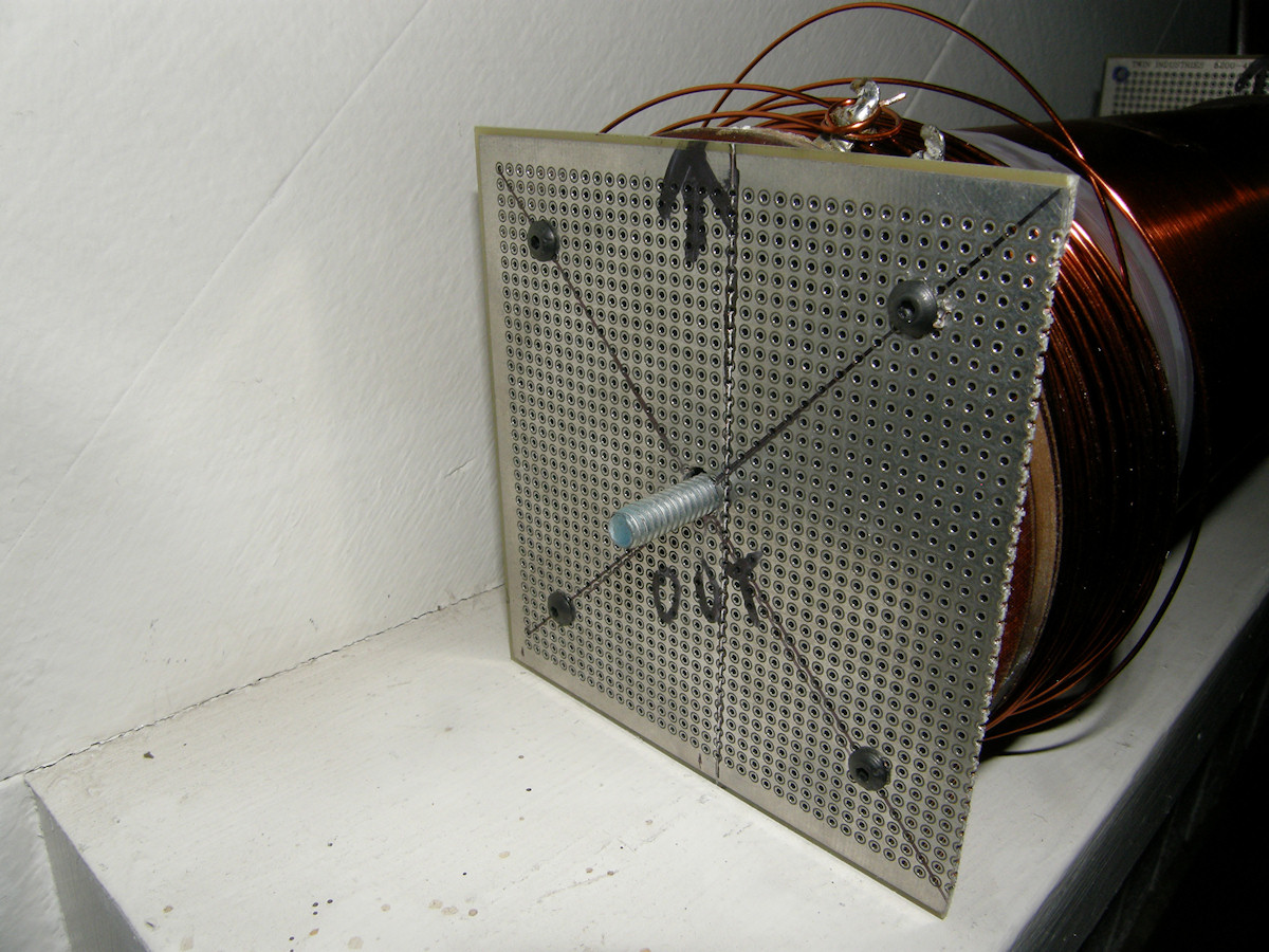
My focus coil rewinding jig - 20151024 This is the focus coil rewinding tool. It will be used one time. So, it needs to be brutally simple. Since this is going to be a one shot deal, all operations are manual. Once started, it may take hours to unwind and then rewind the coil. We won't know how long until I sit down and actually perform this task. It looks challenging. The black storages spool sits on two inch wooden dowel and can slide left and right to track the much wider focus coil as necessary. The focus coil is suspended on its axle and held in place with appropriate nuts and washers. Back tension is controlled by adding a sandwich of metal and rubber compression washers. I adjusted the axle nut tightness to set a strong back tension that will be absolutely necessary for the job. Video: Focus Coil Rebuild Part 1 (16:15) - 20151028 Watch me use my amazingly cheap machine to remove the wire from the old focus coil. I didn't know it yet, but the coil was made of six layers of windings. More work than I could initially guess. During this process, I found that the wire was broken in four places due to corrosion. Both ends were corroded off of the contact terminals. Then there was a break in the second layer, layer five counting from the inside out, in the very front of the coil. I believe something corrosive was splashed on the front of the camera at some point in its history. The final break was in the middle of winding number four. More corrosion. Video: Focus Coil Rebuild Part 2 (08:00) - 20151028 Now watch me wind the wire back onto the focus coil using my amazing little machine. It was extremely challenging until I taped the machine to the desk top. Then it was only very challenging! Video: Focus Coil Final Assembly (16:00) - 20151109 I put the old camera back together again and prepare for the next round of electrical testing. Will it work now? I won't bet on it. Just to be safe. It is very likely we have not hunted down every gremlin in the works yet. But, I will point out that all of our progress, up to this point, has been positive. That's quite an achievement considering the original condition of the equipment. 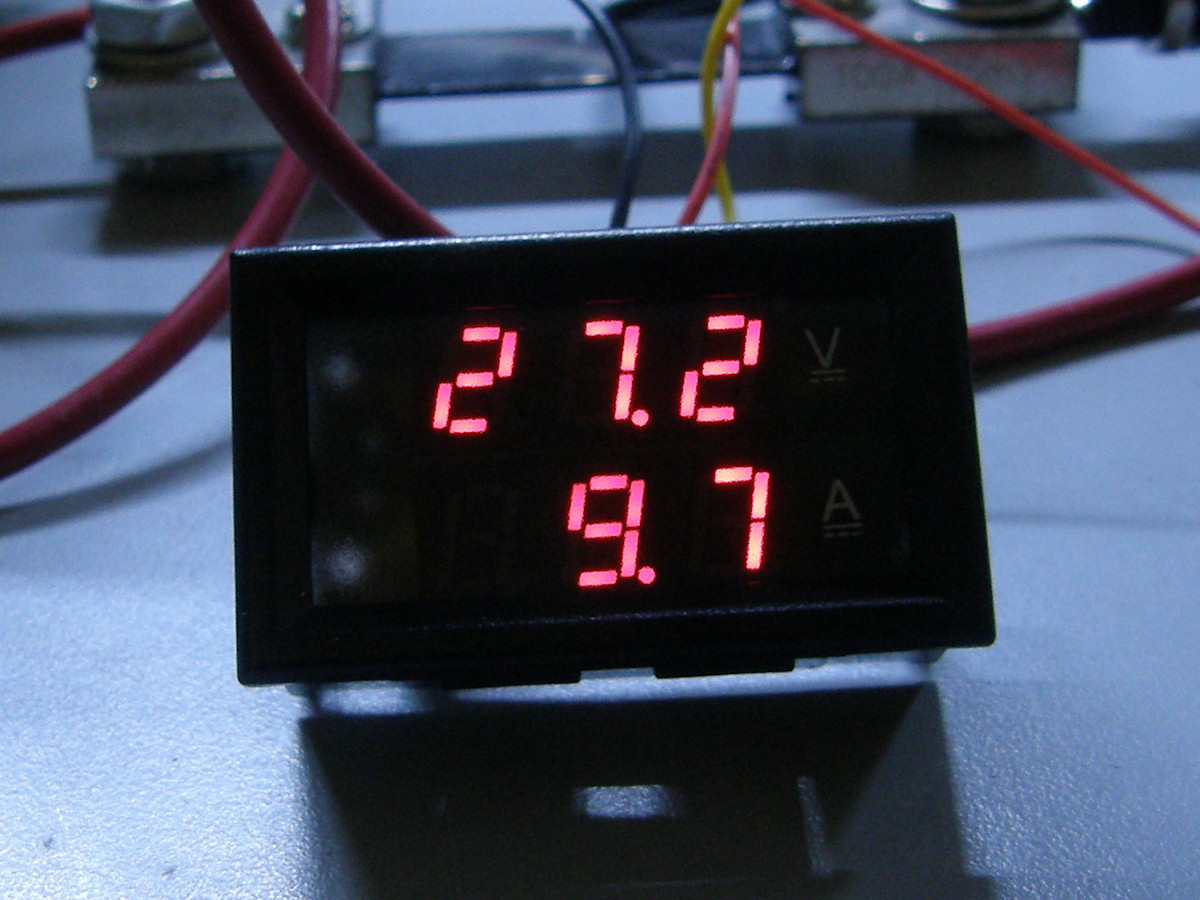
Restoration Project Update - New Power Supply Purchased Today- 20151122 The focus coil is rebuilt and reinstalled. Under power, it has an approximate 12 volt drop acrossed it. This is extremely good news indeed. It means that the replacement 6H-4 ballast tube is working correctly. Focus current is now a very comfortable 765 mA, well within the proper rating for this tube. However, the measurement is not final as will be detailed next. Unfortunately, my DC power supply is beyond topped out at over ten amps of turn on current. As you can clearly see in the photo, after the intial surge, the 28 volt circuit is loading the 5 amp power supply a little too heavily. It is not even able to get up to 28 volts. I purchase a brand new 28 volt, 14 amp, switching power supply on Ebay this morning. That will certainly have enough Wheaties for this job! Restoration Project Update - Checking the manual... DOH! - 20151123 According to the official manual, this camera... I mean conversion unit uses the following voltages and currents: +28 VDC @ 4.8 amps +405 VDC @ 200 milliamps -53 VDC @ 5.2 milliamps Obviously, we have discovered a new problem. The darn thing is pulling an extra 5 amps! I am guessing a shorted gigantic capacitor. The camera is not supposed to draw 10 amps of current after all. That's a relief. I know what I will be working on over the coming long weekend. I am still very pleased that the focus coil repair was 100% successful. Restoration Project Update - Seasons greetings - 20151213 Be patient my loyal readers. It is likely that the 6H-4 ballast tube is mislabeled or possibly defective. I have directly verified with the Amperite company, which is still in business today, that this tube should regulate current at 700mA or 0.7 amps. I can obtain brand new freshly manufactured 6H-4 tubes for $50 each. Obviously this requires budget preplanning and it is the Christmas season with all of its additional costs. 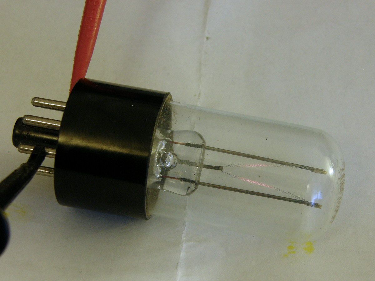
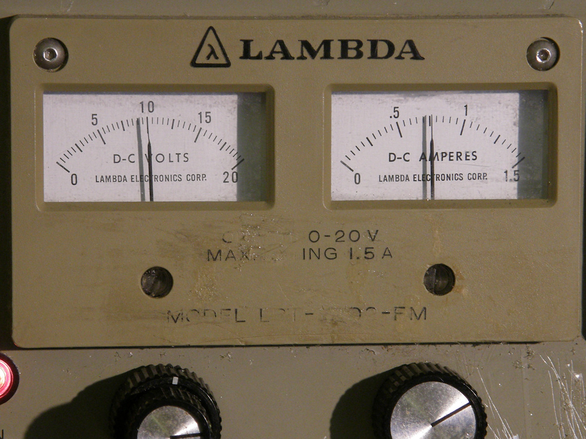
Testing the 6H-4 ballast tube - 20151229 The 6H-4 ballast tube is rated at approximately 3/4 Amp with a ten volt drop acrossed it. I set the power supply for ten volts, set the current limit to 1 amp, just in case, and applied power to pins 1 & 7 on the base of the tube. Low and behold, the darned thing works just fine. If you look closely at the resistance wire inside the 6H-4, you can see it glowing slightly. This is normal. That little sucker sure gets very hot very quickly too! It is dissipating 7.5 watts of power in operation. I have verified the focus coil circuit and all of its resistance readings. There is no problem with the focus coil or this regulator tube. The excess current may be getting pulled elsewhere in the system. The remaining load on the +28 volt input is just tube the heater strings, for the most part. I can trace a few milliamps to the cathode circuit of V121. But, since there is no 405V B+ or -50V bias applied at this time, that circuit is drawing no current any way. 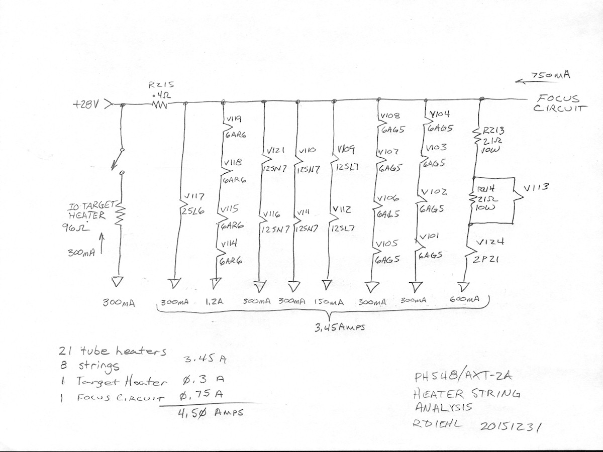
Sanity check and analysis of the expected heater currents - 20151231 There are 21 tube heaters wired in 8 series-parallel srings. Sort of like Christmas lights. Each string pulls the same current through each heater in that string. We find the total tube heater current for each of the 8 strings and then simply add them up. I obtained the rated heater currents for the tubes from their respective datasheets, easily located on the web. My current calculations will be slightly lower than reality. The datasheet numbers are based on running the heaters at a clearly defined operaing voltage. This camera design runs the tube heaters about 1 volt higher than normal. So they will pull slightly more current as a result. My math is close enough for checking what we should expect to measure. This verifies that the expected current should be a little less than 5 amps. This camera is pulling almost ten amps. The question is why? The next step is to pull all of the vacuum tubes out of the camera, opening all of the heater circuits, and then checking for current flow. There should be none at that point. This is an active project. Check back occasionally to follow the progress. REFERENCES: 1. PDF [Denson Electronics Flyers #774 and #792]. Documentation for the PHX548/AXT-2A military image orthicon camera. Produced by Al Denson in 1974. Denson Electronics was a surplus store located in Rockville, Connecticut in the 1960s and 70s. Denson specialized in surplus and new television equipment of every variety known. When I built my first vidicon cameras in the 70s, Al Denson was gracious and answered every single one of my letters and made me great deals on the parts I needed. 2. PDF [1945 RCA 2P21 Image Orthicon Tube] 3. PDF [1953 RCA 5820 Image Orthicon Tube] 4. PDF [1954 RCA 2P22 'MIMO' Miniature Image Orthicon Tube] 5. PDF [ 940C Series high voltage capacitors] 6. PDF [ Amperite ballast tubes] Old school constant current regulators RELATED LINKS AND RESOURCES:
BIBLIOGRAPHY:
[HOME] [ELECTRONICS PROJECTS] [PART 1] Created: October 17, 2015 Last updated: December 31, 2015 |