| LabGuy's World: 1945 RCA CRV-59AAE
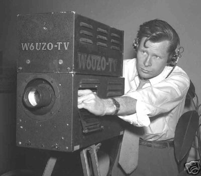
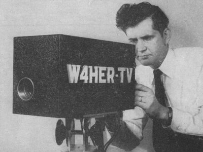
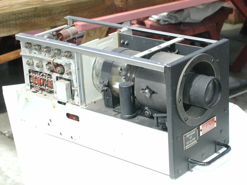
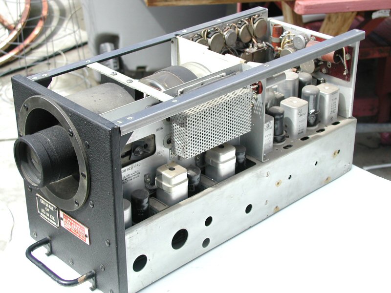
Iconoscope Camera New! 060327 IN THE BEGINNING: 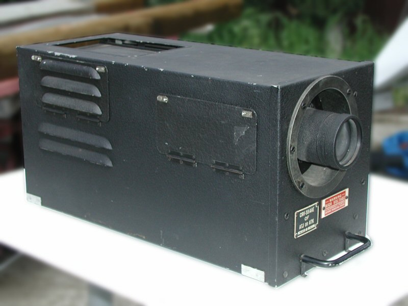 Labguy's 1945 RCA Guided Bomb Camera [RIGHT SIDE VIEW] [LEFT SIDE VIEW] [UNDER SIDE VIEW] [TOP SIDE VIEW] My CRV-59AAE is 20" long by 9" wide by 10"high. It weighs a mere 33 pounds. It is at least 60 years old and in excellent condition. It represents some of the finest in miniaturized technology for its time. It uses an iconoscope tube as the imager. It contains 17 vacuum tubes, including the iconoscope tube. All tubes are present and accounted for. It was originally intended to be used in a remote piloted glide bomb. Internal markings and quality control stamps indicate this is a US Navy surplus item. Here is some more detailed history about that: This camera was part of the ATJ/ATK (transmitter) ARK (receiver) system for the first generation of "smart bombs." The development project was called PROJECT BLOCK. the ATJ camera is part of "Block 3", an incremental improvement over the Block 1 systems. (Block 2 is not mentioned in my resources.) They were used in glide-bombs, as well as aboard war-weary B-17s and B-24s that were packed with explosives and used as unmanned "kamikaze" type weapons against targets in Europe, notably German submarine pens. The planes had to be flown by a crew at takeoff but after that the crews bailed out and a "mother ship" took over with radio control. It was one of these aircraft that killed Joseph P. Kennedy Jr. when it exploded after takeoff from a base in England, in 1944. (There is even more information found on the page links at the end of this article, bottom of the page.) All of that is too dreary, though heroic, for these times and only the beginning of these camera's fascinating story. Let's examine their role following the end of the war. Labguy's World got this one in 2006. Many were made, but hardly any (relatively speaking) where used, and so became electronic surplus after the war. Some television stations went on air with these as their first camera. Many found uses by experimenters and as surveillance cameras. Amateur radio operators also used them for ATV operation at the beginning of the 1950s and continued well into the 1980s. Below are two fine examples of this camera being used for ham radio amateur television. The photo of W4HER is positively from 1953. But, what is he looking at? [Homer Apple's 1953 W4HER Iconoscope Camera]
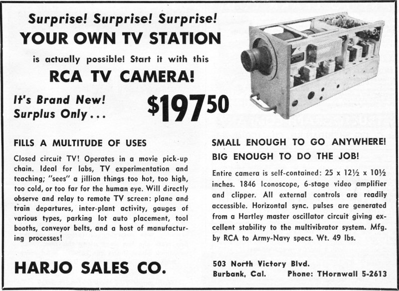
My bomb camera (bombcam) arrived today (060329) via UPS and amazingly was not totally destroyed for a change. I received an excellent deal on this camera from my newest friend Anthony, in Quebec Canada. Thank you kindly, sir. According to some literature provided by Anthony, the camera was originally purchased in May of 1956 by a chemical company that probably used it for surveillance or to watch some batch process. It was originally sold by Harjo Sales Co. of Burbank, California which sold them for between $50 used without iconoscope and $200 for a complete brand new one. Anthony obtained it next and used it as a "kid-cam" in his back yard. That makes me the third owner.
The idea now is to proceed to full cleaning, tube checking, power supply restoration and finally camera bring up. This will take a few days to weeks as I want to bring the power supply up very slowly, using a variac transformer. Putting full power to tube equipment that has been stored for years is an invitation to a fire. The filter capacitors are likely to explode right out of the chassis if powered on abruptly. Stay tuned!
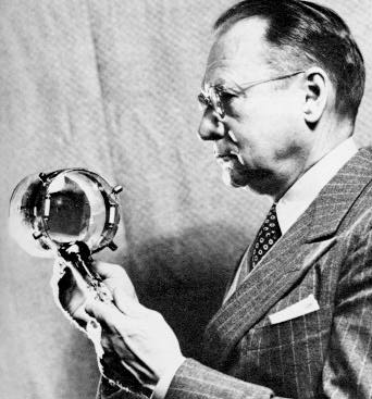
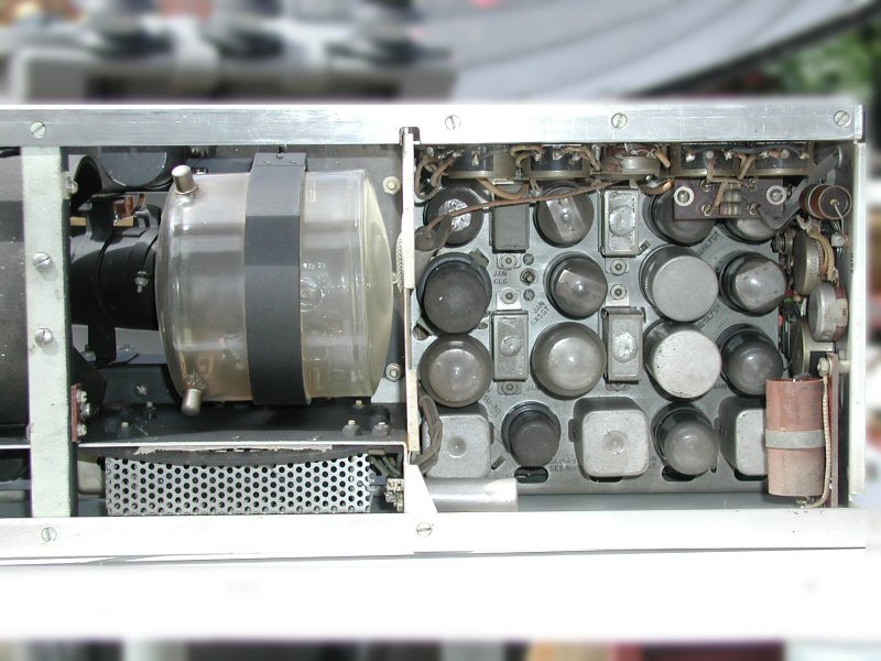
Dr. Vladimir Kosma Zworykin with an 1846 iconoscope tube The CRV-59AAE uses an ICONOSCOPE tube as its image sensor. The iconoscope was invented by Dr. Vladimir Zworykin in the early 1920s while working for Westinghouse. When Westinghouse failed to appreciate his accomplishment, Dr. Zworykin took his inventions to RCA's David Sarnoff. Both men were Russian immigrants and became good friends as well as business collaborators. During WWII, RCA developed these cameras for the military. RCA, Sarnoff and Zworykin all did very well during this time. THE ICONOSCOPE TUBE:
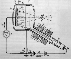
Schematic diagram of the iconoscope tube The iconoscope tube is made of two major sections. The mosaic (G) and the electron gun (W). The mosaic is where the electrical image is produced and the electron gun is the mechanism to read the charge out. Light from a scene is focused onto the mosaic by a lens (L) like in any camera. The front of the mosaic, the side facing the lens, is composed of millions of microscopic silver and cesium droplets (Pm) deposited on a sheet of polished mica. Every silver globule is insulted from its neighbors, allowing each to accumulate an independent charge for that point in the scene. The back side of the mica (Si) is completely silver plated. This back plate and the silver globules, being insulated by the mica, forms millions if tiny capacitors with one plate in common. All of this wrapped in a glass envelope which is then pumped down to a hard vacuum. Any air left in the tube would degrade the mosaic and defocus the electron beam. IMAGE DISSECTION: The electron gun produces a fine focused beam of electrons, kind of like an invisible laser pointer. After this beam of electrons exits the electron gun, they enter a series of magnetic fields that help to further focus the beam and to bend it up, down, left and right across the face of the target. The magnetic fields are produced by an assembly of wire coils placed around the outside of the neck of the iconoscope tube. Two of the coils provide scan deflection (S) and the third coil (F) helps focus the electron beam. A magnetic focus coil is shown in the diagram, but one is not used with the the 1846 iconoscope used in the CRV-59AAE. As the electron beam scans across the target, it deposits electrons onto the silver globules. Light, striking the globules, bleeds off the electron charge. The next time the beam scans a given point, it only needs to replace the bled off charge. Extra electrons from the beam are repelled by the charged spot and return to the collector ring (K). During the charging steps, a weak electrical signal is produced by the solid silver plate on the back side of the mosaic. The collector ring also drains away secondary electrons produced by light striking the mosaic. These secondary electrons would otherwise rain back down onto positive spots of the mosaic, changes the charges there. The effect would be shaded halos around bright spots in the scene. The iconoscope tube has one more, very serious and insolvable, problem. Because the signal is developed on the common plate of a capacitor formed by the two layers of silver on both sides of the mosaic, there is no DC component to the signal. A capped lens will cause the tube to produce a 50% grey signal! This means that the black level of the picture will float all over the place dependant on the average picture level. For low contrast scenes, the black will float "up" to become a dark grey. White will pull down to the high grey range producing a washed out picture. On the other hand a high contrast scene can drive low and medium grey levels down to the black level and below. A picture tube can not put out negative light! This is called black clipping. SCANNING GEOMETRY: Observe how the tube is constructed and assume it is oriented with the "electron gun down" or below the mosaic as shown in the image above. The electron gun and the neck of the tube are vertically off axis from the mosaic. This is to allow the optical image from the lens to project onto the mosaic unobstructed. Recall that the optical image is inverted and the top of picture is the bottom of the mosaic. So, if we just drove the electron gun deflection coils with constant amplitude voltages, the following would happen: First the electron beam would be out of focus over most of the mosaic, assuming it is focused correctly in the center of imaging area. This is because the bottom of the mosaic (top of the image) is closer to the gun than the top of the mosaic by quite a large amount. The distance from the end of the electron gun varies depending on where the beam is landing at any given instant. Second, if the horizontal scan current amplitude is constant, the scan lines at the top of the mosaic would be longer than the ones at the bottom. The scan angle stays fixed as it exits the electron gun, but the beam travel distance is not. The farther the beam travels, the wider an arc it traverses. The result is a raster that is wider at the top than at the bottom or a trapezoid. This is called keystone distortion and is the same as if a movie projector is aimed upward at the screen. The projected pattern looks exactly like the keystone in the top of an arch. All of these "distortions" must be counter acted in order to get geometrically correct coverage and proper focus across the entire mosaic imaging area. In order to correct the keystone problem, vertical scan voltage is fed over to the horizontal scan stage and is used to modulate the scan width in real time. This is the same trick performed in many projection television sets to this day. As the vertical scan current increases, and the beam moves up the mosaic, the horizontal drive current is gradually decreased, lengthening the scan lines as they get closer to the top of the mosaic. An adjustment is provided to achieve the correct current mixing levels and a nice rectangular raster on the mosaic. In a way similar to the horizontal scan correction, the electron gun focus voltage is varied in real time by adding a pair of parabolic waveforms to it. These waveforms are derived from the scan circuits. With the use of some shaping and scaling circuits, these waveforms are added together and finally added to the fixed focus voltage at the first anode of the electron gun. Dynamic, real time electron beam focus across the mosaic is achieved. Where have you seen this before? Ever seen a Sony Watchman TV and it's "paddle tube" CRT? The more things change, the more they stay the same. CRV-59AAE CIRCUIT DIAGRAM:
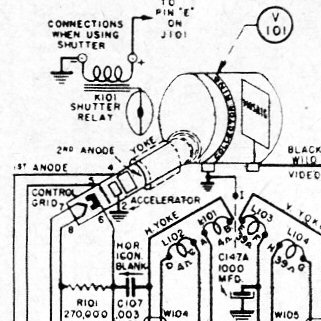
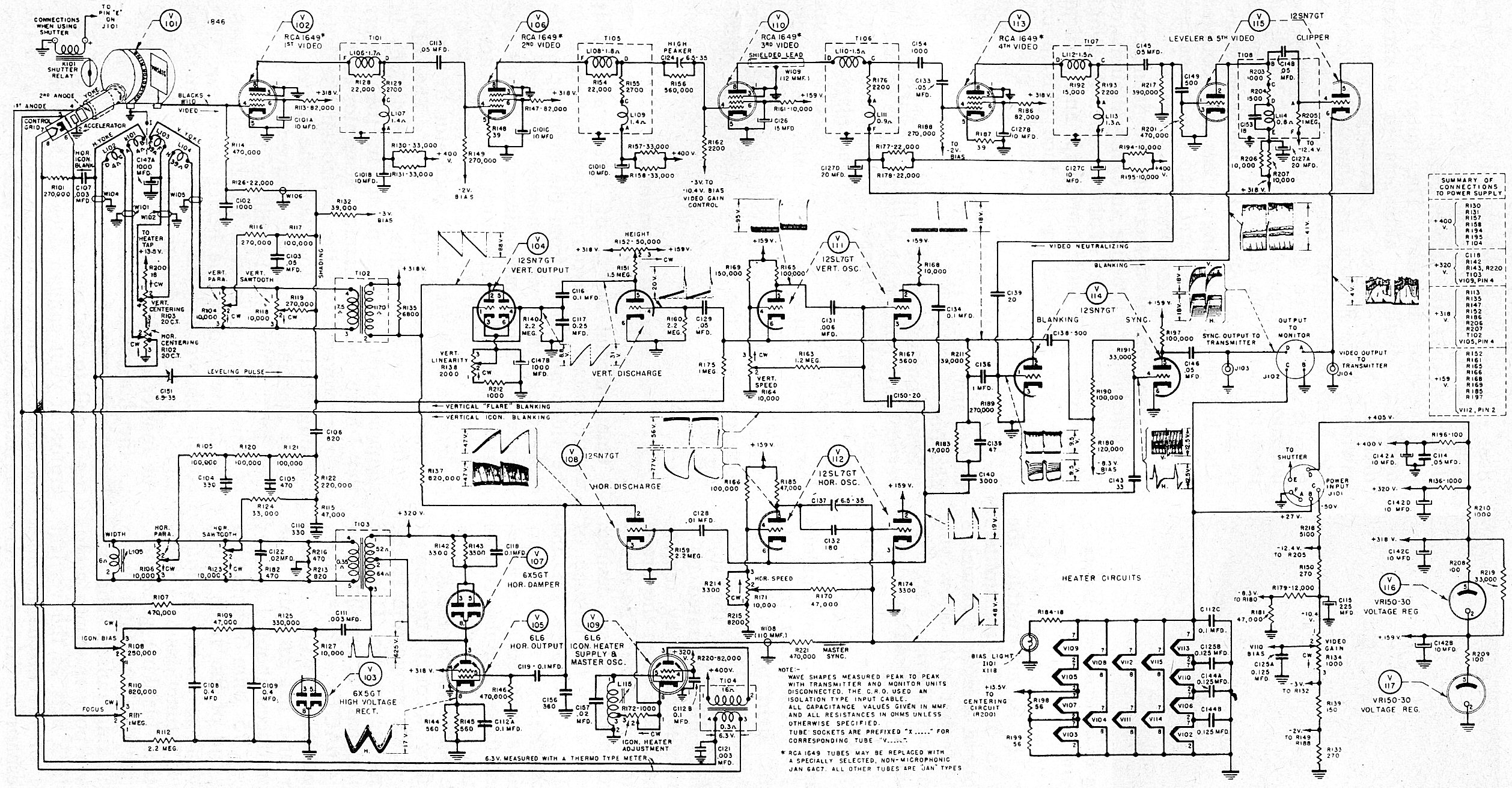
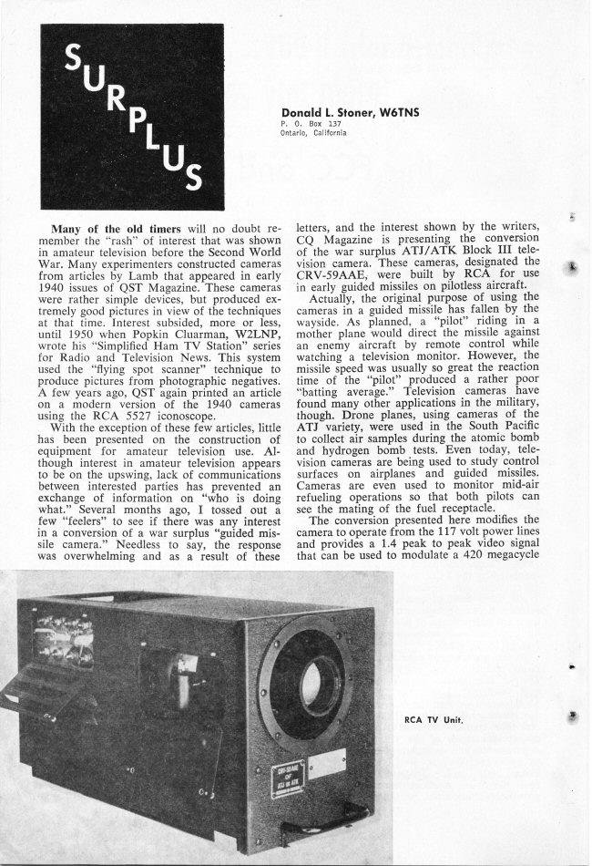
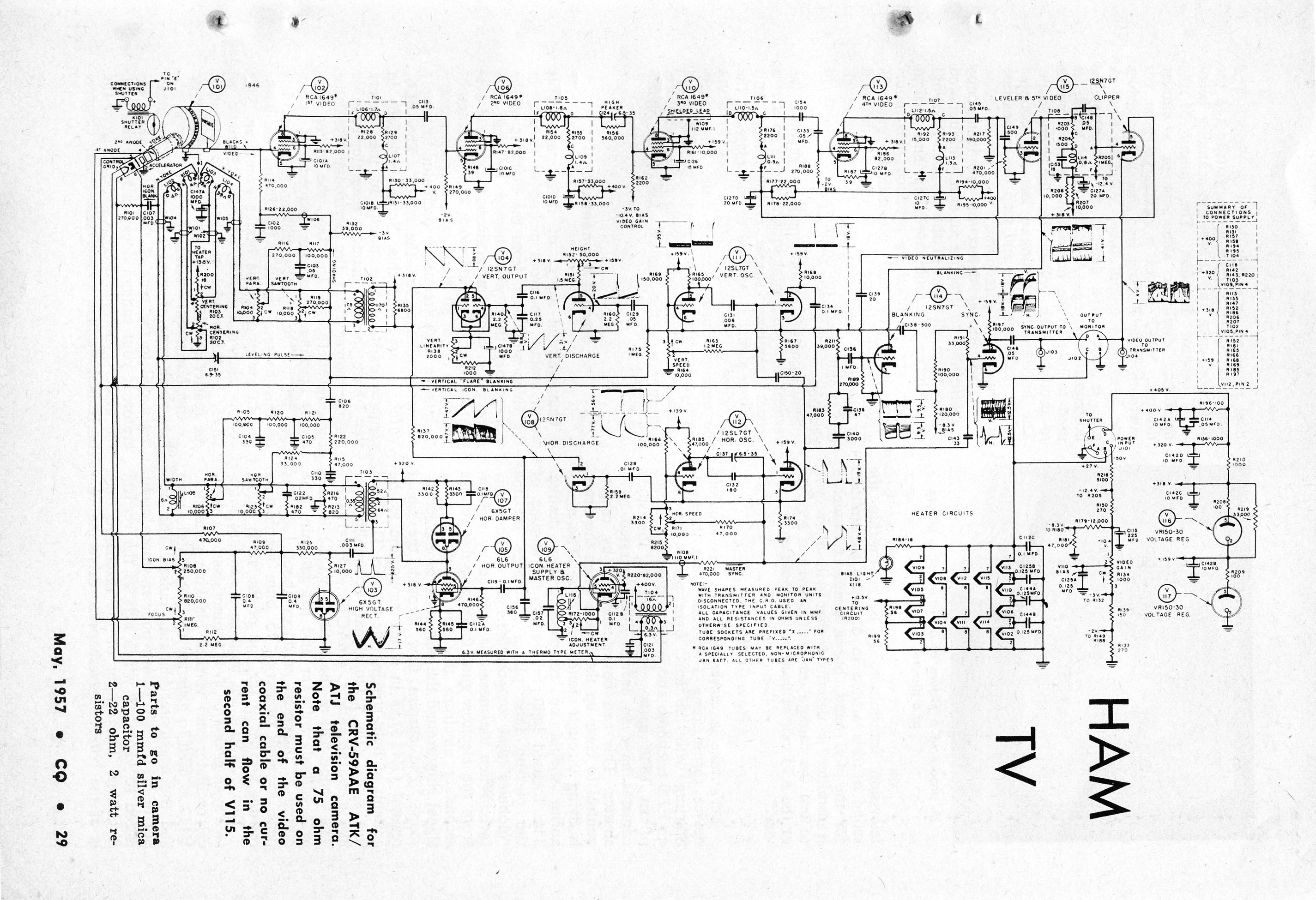
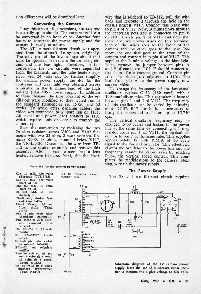
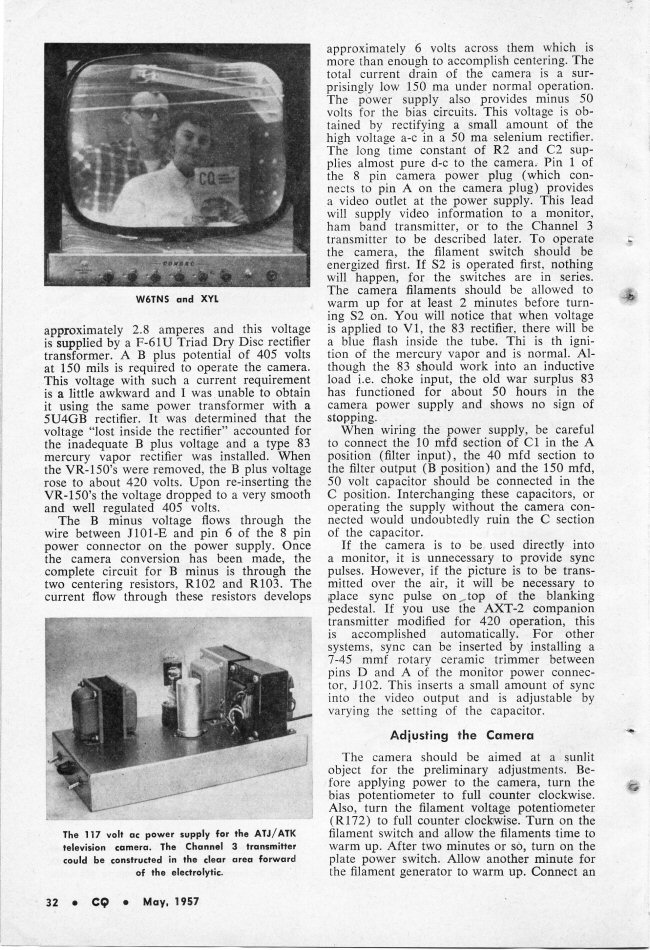
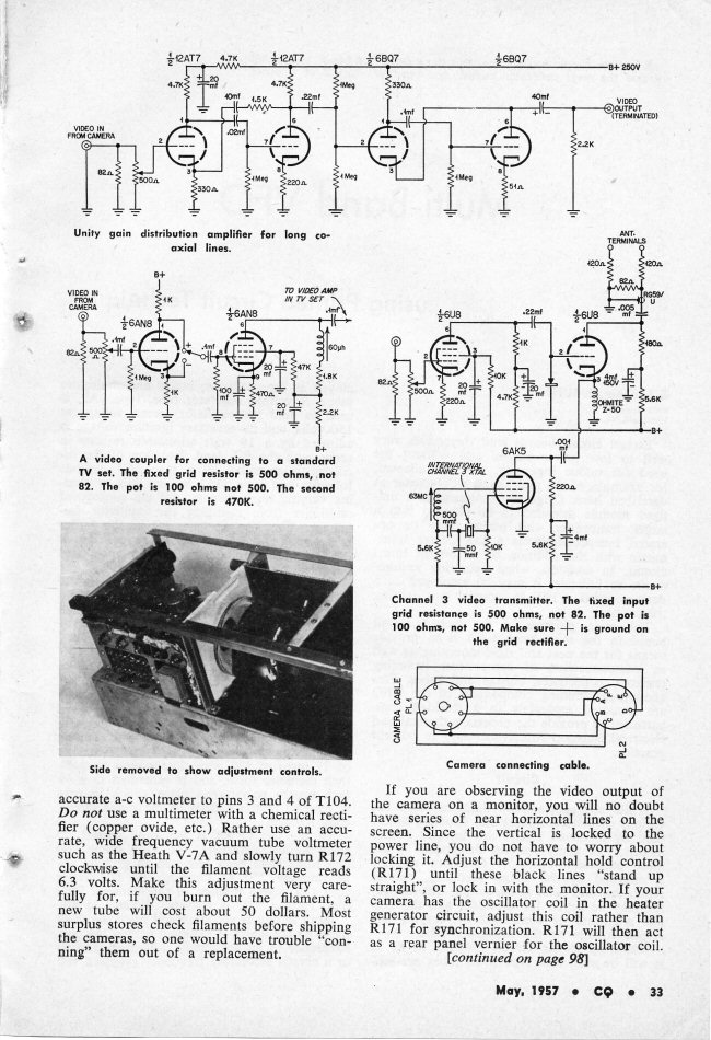
SCHEMATIC OF THE CRV-59AAE ICONOSCOPE CAMERA (2500x1300, 956KB) This is the electrical schematic for the your enjoyment and fascination. It is probably best to download the file and print it out, as the file is quite large. The resolution is 300DPI. Moving right along... The bombcam is all vacuum tube, "no state", technology! Glow FETs! Not an IC or Transistor to be found. Not even a germanium, silicon or even a Selenium diode! Not a hint of solid state technology. I was told these could be used to observe atomic tests in the 60s. Hmmm. BOMB CAMERA RESTORERS TAKE NOTE: Be sure to read the entire article from the May 1957 CQ magazine included below in the bibliography. There are some subtle differences between various incarnations of this camera that must be taken into consideration when restoring one of them. Another article, from QST Nov. 1953, on a similar home built iconoscope camera for ham TV, built around the RCA 5527 experimenter's iconoscope tube, will be posted soon. Anyone else who is restoring or has restored one of these may [contact me] to include an entry about their experience on this project's pages. MY CRV-59AAE IN OPERATION: COMING SOON! STAY TUNED! This camera is in very good clean condition and a prime candidate for restoration. I also got a mating power supply, not shown as of this writing, that will be covered in detail at a later time. I think I am going to like this project. The camera is simple enough to have a very high potential for success unlike an image orthicon camera which is way more complicated. RELATED LINKS AND RESOURCES:
BIBLIOGRAPHY:
[HOME]......[MUSEUM OF EXTINCT VIDEO CAMERAS] Created April 1, 2006 - Last updated: December 23, 2007 |