|
LabGuy's World: NBTV - 10-4 Eleanor RGBY Color Video Signal Generator Project
[PREVIOUS PAGE] [HOME] [ELECTRONICS PROJECTS] [NEXT PAGE] [1. INTRODUCTION] [2. HARDWARE] [4. IMAGES] [5. CONCLUSION] 3. SOFTWARE 
Header of the QB64 Timing EEPROM Creator Program There are several steps required to produce the contents for the four EEPROMs on the 10-4 Eleanor video board. These steps are as follows: 1. Create or obtain the binary file for the timing state machine EEPROM. 2. Program the binary file into the EEPROM chip using a device programmer. 3. Create or obtain, then install, the operating software into the Arduino microcontroller. 4. Create or obtain the DEFAULT red, green and blue EEPROM image files. (The files with the numbered images) 5. Create your own raw binary image files. 6. Merge your raw image files into the EEPROM binary files at the locations of your choice. 7. Program the binary files into the image EEPROM chips using a device programmer. 8. Install the chips and enjoy high quality NBTV images on your Televisor. STATE MACHINE 
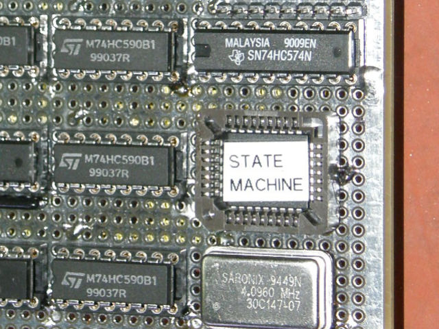
All of the files used in this project are available for download as a zip file on the [CONCLUSION] page of this article. The state machine is the heart of the entire project. It generates the timing pulses that run the video address counters, the D/A converters, as well as the sync and blanking signals for the CVBS output. It can be compared to the punched paper roll in a player piano or the small pinned drum in a music box. The circuitry is very simple, comprised of only five IC chips and the crystal oscillator module as shown in the photo above. The memory chip that contains the timing patterns is clearly labeled. The bit pattern is created with a Quick Basic (QB64) program. It creates a binary file, the same size as the EEPROM chip (524,288 bytes), sets and resets the appropriate bits and places them into this file in the appropriate locations. After that, you simply transfer the binary image into the EEPROM chip with a low cost device programmer. This also applies to the image memories and will be covered on the next page of this article. For those of you who are experienced or very bold, you can work out how the program works for yourselves from the QB64 code and the timing diagrams located elsewhere in this article. This will eneable you to modify, adapt or reuse this circuitry as you see fit in your own electronics projects. This state machine is particularly useful in musical rhythm generators. Using the program is easy enough. After you have downloaded and installed Quick Basic 45 (www.QB45.org), run the program EleanorStateMachine.bas, found in the downloads section of this article on the CONCLUSION page. OR download the ready to use binary file EleanorStateMachine.bin if you don't feel compelled to modify the code yourslef or want to hassle with the QB45. Then program the binary file into the chip as indicated next. PROGRAMMING THE EEPROM 
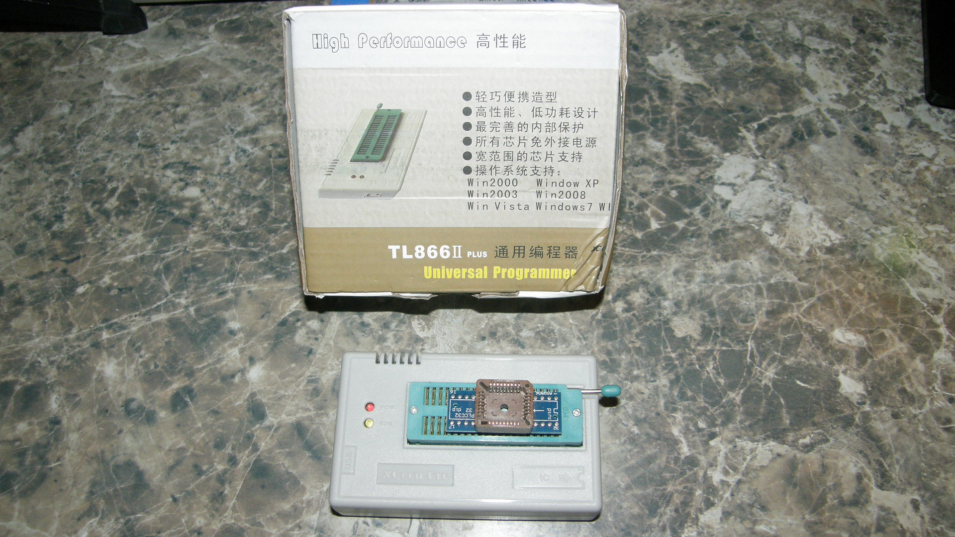
programming the EEPROMs is performed outside the 10-4 Eleanor. I use the TL866 II device programmer. These are available for around $60 on Ebay, Amazon and from other common electronics vendors. Run the included software, load the binary file of your choice, select the device brand and type, press program. When the software says, "Device programmed successfully", install the chip and in the Eleanor and you are good to go. ARDUINO CODE 
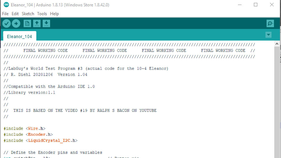
All of the files used in this project are available for download as a zip file on the [CONCLUSION] page of this article. Operation of this code is very simple, it was constructed from bits and pieces found in YouTube videos. The Arduino code here operates as an over glorified DIP switch. It allows the user to rotate the encoder knob and step through the 256 stored images in the 10-4 Eleanor. Code description is as follows. We load the three include files and define the constants and variables used by the program. Next, we define the the LCD display, the rotary encoder and it's interrupt service routing. A zero is written to the Frame Select port in the Eleanor via I2C. The LCD is initialized and the main screen is written. Following this, the code enters the main loop where it awaits interrupts from the rotary encoder. (The user turns the knob.) When the rotary encoder is turned, the Encoder Interrupt Service Routine is called. The direction of rotation is determined and the Frame Number is incremented or decremented as required. Control returns to the Main Loop. In the main loop, the current Frame Number is compared to the last Frame Number. If there is a change, the new frame number is written to the Frame Select port on the Eleanor video board. That's it. [PREVIOUS PAGE] [HOME] [ELECTRONICS PROJECTS] [NEXT PAGE] [1. INTRODUCTION] [2. HARDWARE] [4. IMAGES] [5. CONCLUSION] |