|
Forward: A new type of TV camera utilizing an electrostatic camera tube of the vidicon type is described and the new and novel circuitry which has been employed presents problems which are unique even to those acquainted with conventional vidicon camera units.
Since the earliest days of commercial TV broadcasting, engineers have long desired a low cost TV camera for industrial and consumer use. Many attempts have been made in the past decade to produce such a unit, usually these cameras have been developed around the one inch type 6198 vidicon and its successors of like electromagnetic characteristics. The camera herein described is the first to depart from this general tube type and it is believed in the future there may be further departures in attempts to lower the complexity and cost of such units.
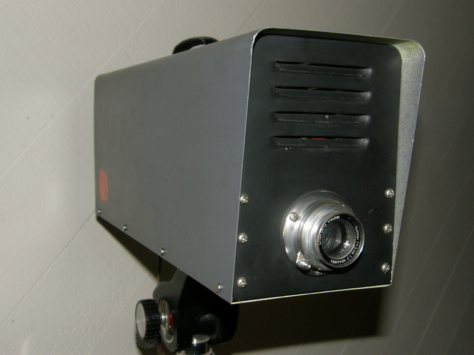
The Al-Dee camera represents the first successful attempt by any manufacturer to package a complete unit of the relatively high technical characteristics and low cost in one unit. Numerous desigin firsts have been incorporated which will become apparent as the design features are explained. The camera itself utilizes a 2 inch electrostatic vidicon of unique design and a 2 inch F1.9 lens which is interchangeable with any Leica/Cannon screw mount lens or accessories. The use of a standard 35 Leica/Cannon lens mount marks a departure in this respect as such lenses are readily available of excellent quality at relatively low cost in a wide variety of focal lengths and F stops eliminating the need for specialized high cost 16mm lenses, as wells as providing almost unlimited versatility as regard to the availability of accessories and attachments.
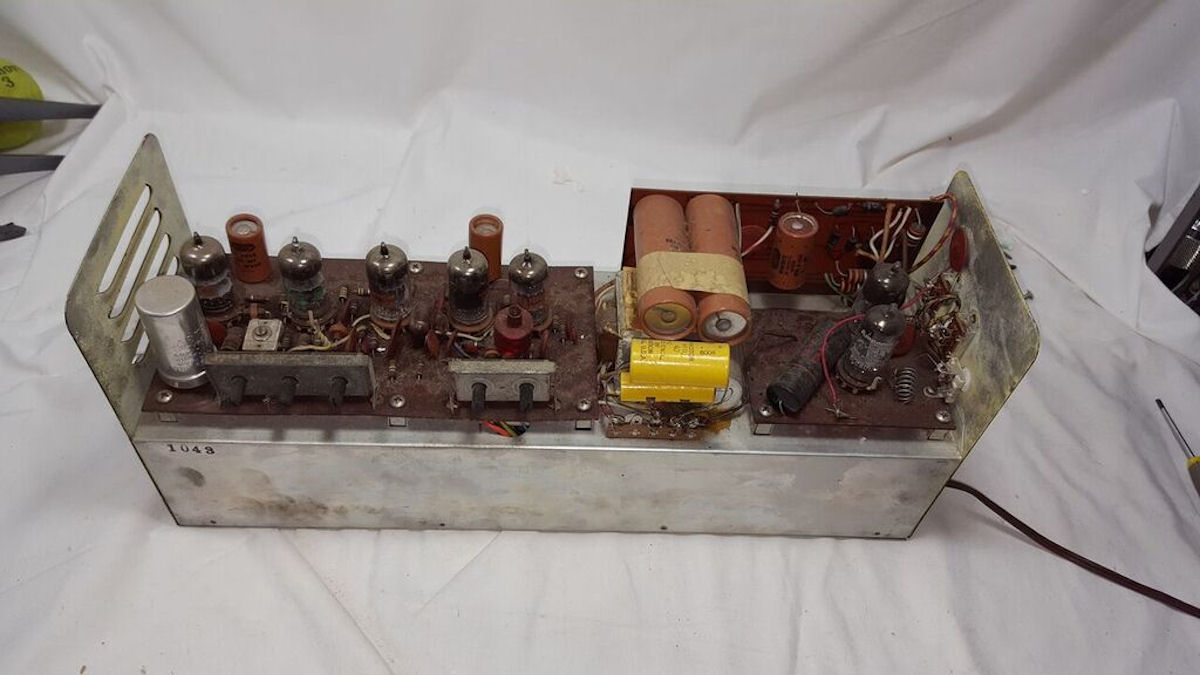
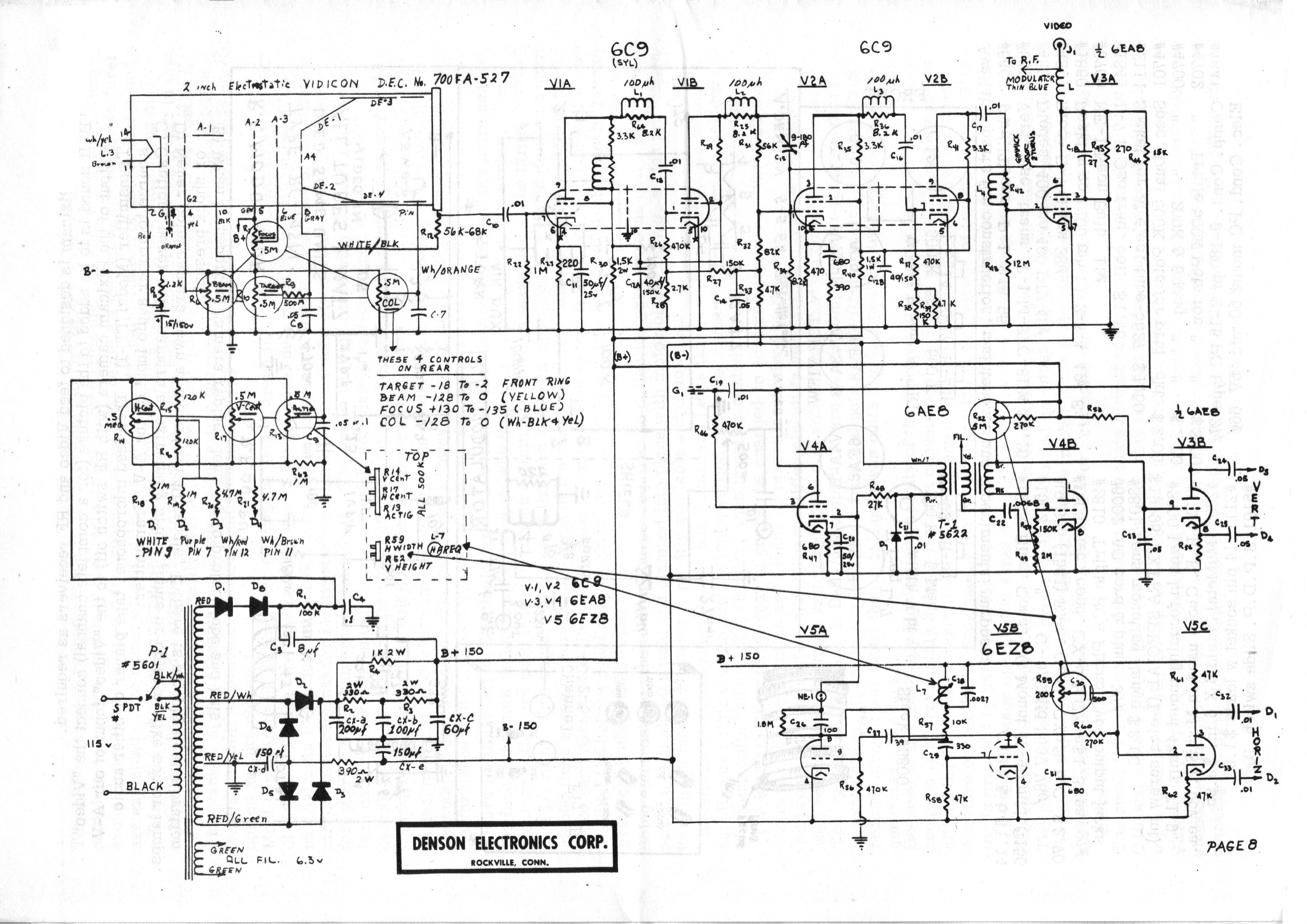
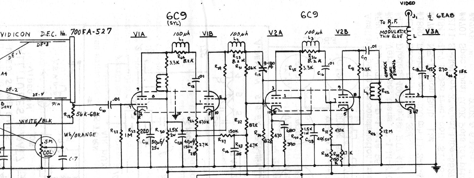
Most cameras have, in the past, followed a general trend in utilizing video amplifier circuits of the RCA TV EYE type and again we have here a radical departure in the utilization of the new Sylvania 10 pin dual tetrode 6C9 tube in a series peaked circuit. Because of the different circuit requirements for electrostatic scanning, the scanning circuits are also totally different from the other cameras of this class. The entire package containing 7 tubes plus the 2 inch camera tube weighs only 11 pounds and is completely self contained in a case with an overall length of 17", and a height of 6 3/4" by 5" wide and consumes the minimum amount of 40 watts from a standard 115 volt 60 cycle AC power source.
In designing and producing camera systems, the first consideration was given to price; and secondly to performance. The end result, however, is a camera that actually compared in performance to its competitors so that little or nothing was sacrificed.
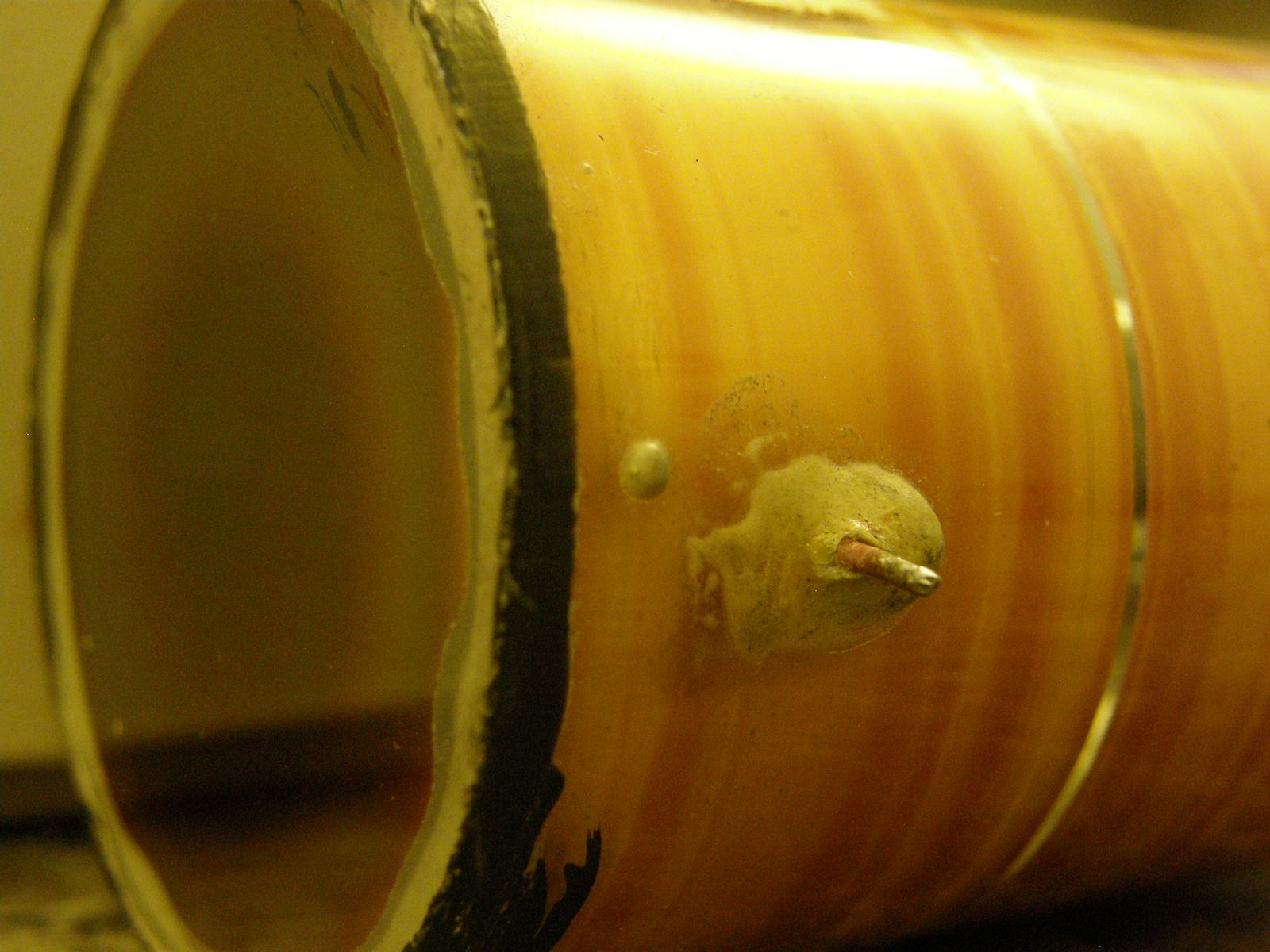
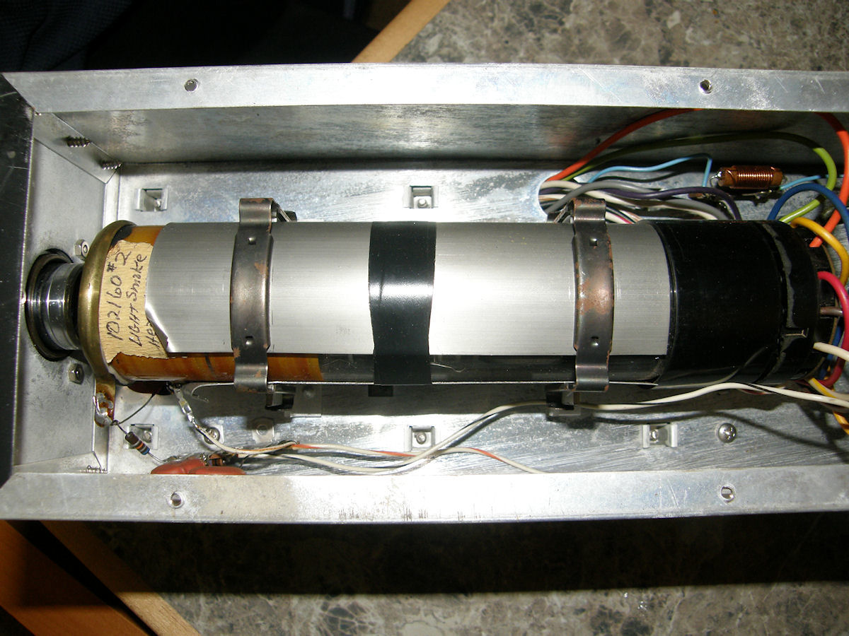
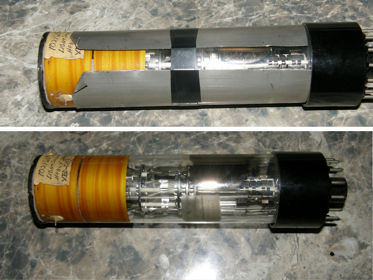
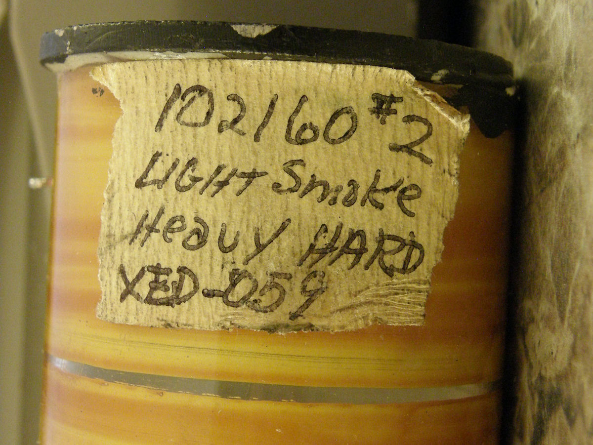
Figure 1 - Indium seal and collomator electrode - 20160816
Figure 1 is the actual 2 inch electrostatic camera tube showing the Indium pressure seal on the face and a split deflection plate system which gives a common deflection center. The electron optics are such that a .0015 inch defining aperture is magnified at the target surface in a 1/1 ratio. The actual resolution of the tube has been measured in a high definition system as 650 lines at the center and 250 lines at the corner. In this camera, it is limited by the video band pass to 400 lines. The tube is again unique in that it uses no mesh nor wall screen and that the bulb is made of G-12 glass with a LIME glass face plate. The absense of a mesh practically eliminates beam flutter, a common problem with most electrostatic vidicons.
Being electrostatic, the tube of course requires no deflection yoke or focus coil. It is wrapped in a high Mu 80 shield and clamped into place with motor block clamps, a high production item in the fastener induistry, readily available and of low cost.
The lens as previously mentioned, has a standard Leica thread and the particular lenses supplied as original equipment, when specified, with the camera were especially designed for these units and are of 7 elements, anastigmatic, coated, color corrected construction. The lens mounting flange may of course be changed to accommodate other lenses such as thsoe used by Practica and Pentax or others as desired by the user.
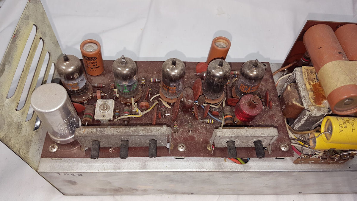
VIDEO AMPLIFIER - 20160816
As presently constructed, the video amplifier circuit is very stable, operating the tubes well below their maximum ratings and gives a .15 volt composite video output. (.15V? maybe means 1.5V?) The type 6C9 tubes used in the video amplifiers are series compensated tetrodes, contrary to expectations, there is no perceptabible front end noise. The first stage has no plate circuit peaking since it was found the overall gain was quite high and peaking tended to cause a regenerated white noise.
Because of the relatively high output capacity (capacitance) of the electrostatic pickup tube, the correction required is approximately 3 times that of a conventional 6198 type vidicon. Under these conditions the LR peaker would have caused a loss of gain compared to the RC peaker used. Aperture correction is provided by the RC combination in the cathode of the 4th stage. Biasing is provided by various means with the first 3 stages operating with about 2.0 volts of bias while the 4th stage operates at about4.0 volts. The average stage gain is about 12 times.
A plate follower output stage is used for coax line driving, DC restoration and sync mixing. The plate of the tube is at ground potential so that no video coupling condensor is required for the 75 ohm coax output. Sync pulses are mixed in the plate load resistor and the grid/cathode combination serves as a DC restorer, clamping on the blanking signal from the camera tube.
The small trim condensor located in the plate circuit of the first video amplifier labeled C15 and located just to the rear of this tube,may be adjusted for video response with minimum capacity usually giving the widest band pass and the lowest gain.
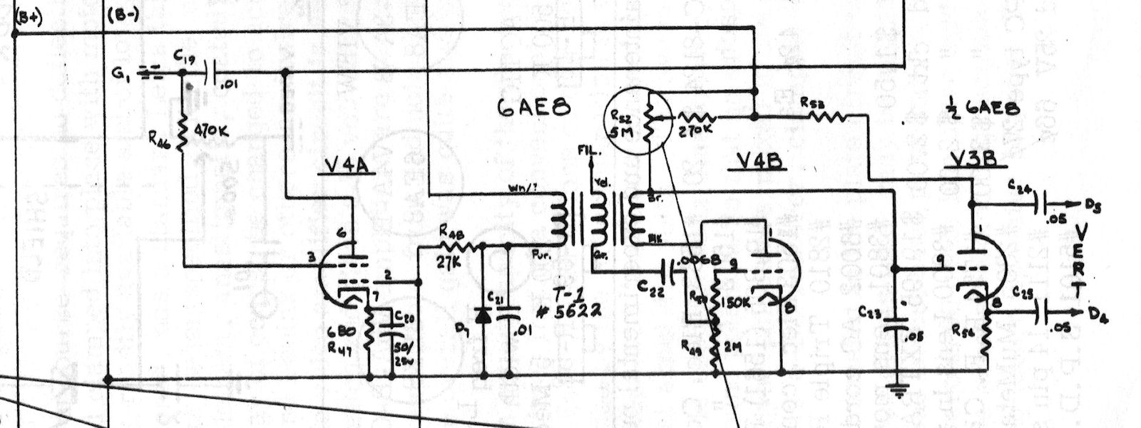
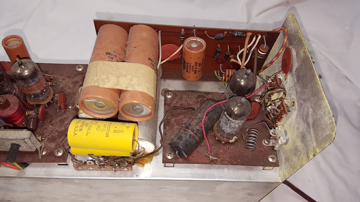
VERTICAL CIRCUIT - 20160816
Numerous 60 cycle line drive systems were tried and eventually abandoned in favor of the more expensive blocking oscillator type which gives superior blanking and sync signals being less responsive to power line fluctuations. The output of the vertical blocking oscillator is directly coupled to a phase inverter which drives the deflection plates. (The Stancor A8124 transformer was found to give superior results in this particular cicuit configuration.) The vertical centering control (R14) is on the top, side mounted adjustment nearest the front of the camera while the certical height (R52) is the top adjustment near the back of the camera or counting from the front would be #5 control.

HORIZONTAL CIRCUIT - 20160816
Horizontal deflection is provided by ringing coil (L7) mounted on the top near center of the large printed circuit board used in a stabilized multivibrator type of cicuit feeding a direct couple phase inverter which feed the horizontal deflection plates. It is usually unnecessary to readjust the horizontal frequency at any time but such an adjustment become necessary a suggested method would be to lightly couple the TV camera output to a conventional home type TV receiver which has been previously locked to a fringe area signal from a standard TV broadcast station. Readjustment of the slug in the ringing coil (L7) may then be made to insure horizontal lock. The horizontal centering control (R17) for the camera tube is the #2 control from the camera face while the horizontal width control (R59) is #4 from the camera face.
SYNC & BLANKING ... Various sync and blanking arrangments were devised and tried but the one finally incorporated into the camera proved to be the most satisfactory even though it would require the use of an additional tube section which low cost cameras try to avoid. Positive pulses are taken from both the horizontal and vertical oscillators and applied to RC networks to the grid of the blanking pentode. This tube is biased so that it is cut off between pulses and the pulse peaks saturate the tube below the knee of the pentode curve. The blanking and sync are therefore squared, of uniform height and of more than adequate amplitude to blank the camera tube.
BLANKING ... It will be noticed that the electrostatic camera tube is blanked in a somewhat unsusual manner and that the beam control is also quite different than the usual practice. The camera grid is always at 0 volts with respect to the cathode, especially during blanking, so that grid/cathode diode effect can be used to provide DC restoration to the blanking pulses. Beam current is varied by varying the voltage on G2 (base pin 4) this is analogous to varying the plate current in a triode by varying plate voltage. There are two reasons for this: The first is that it permits the grid to be used as a DC restorer. The second is that by lowering the voltage on G2 to the lowest possible limit, the effect of the econdary emmissions from the defining aperture are reduced. When G2 is high, an ion spot sometimes appears at the center of the picture. This could be eliminated by using a wall screen or mesh in the tube but this would greatly increase the tube cost.
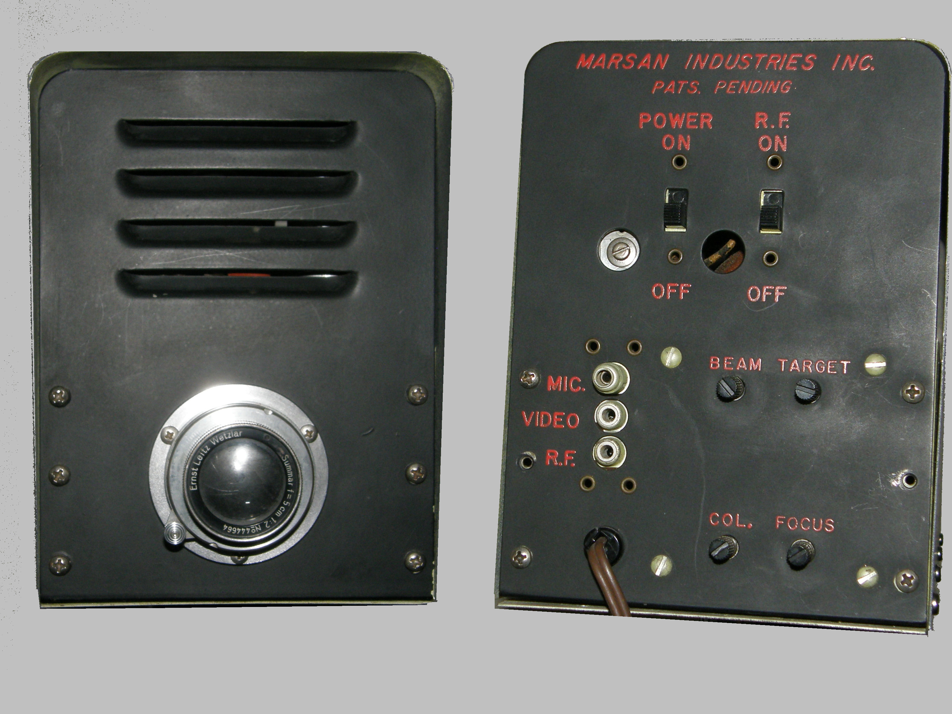
OUTPUTS ... Two standard RCA audio type jacks are provided on the rear of the camera for supplying the camera output to use with associated equipment. The video output as originally stated is a plate follower for feeding 75 ohm coax cable giving approximately one volt with a composite signal containing all blanking and sync information providing a resolution of approximately 400 lines. This output also feeds an internal RF modulator circuit which takes the applied composite video signal and modulates it to a standard U.S. channel tuneable by the user from channel 2 to 6. This has a second harmonic output and may be received acceptably on U.S. channels 7 - 13. However, a bandpass filter will be needed if the RF is to be mixed into a master antenna system. The output of the RF oscillator is also for 75 ohm coax and it is suggested that a (balun) transformer be used when feeding conventional 300 ohm circuits.
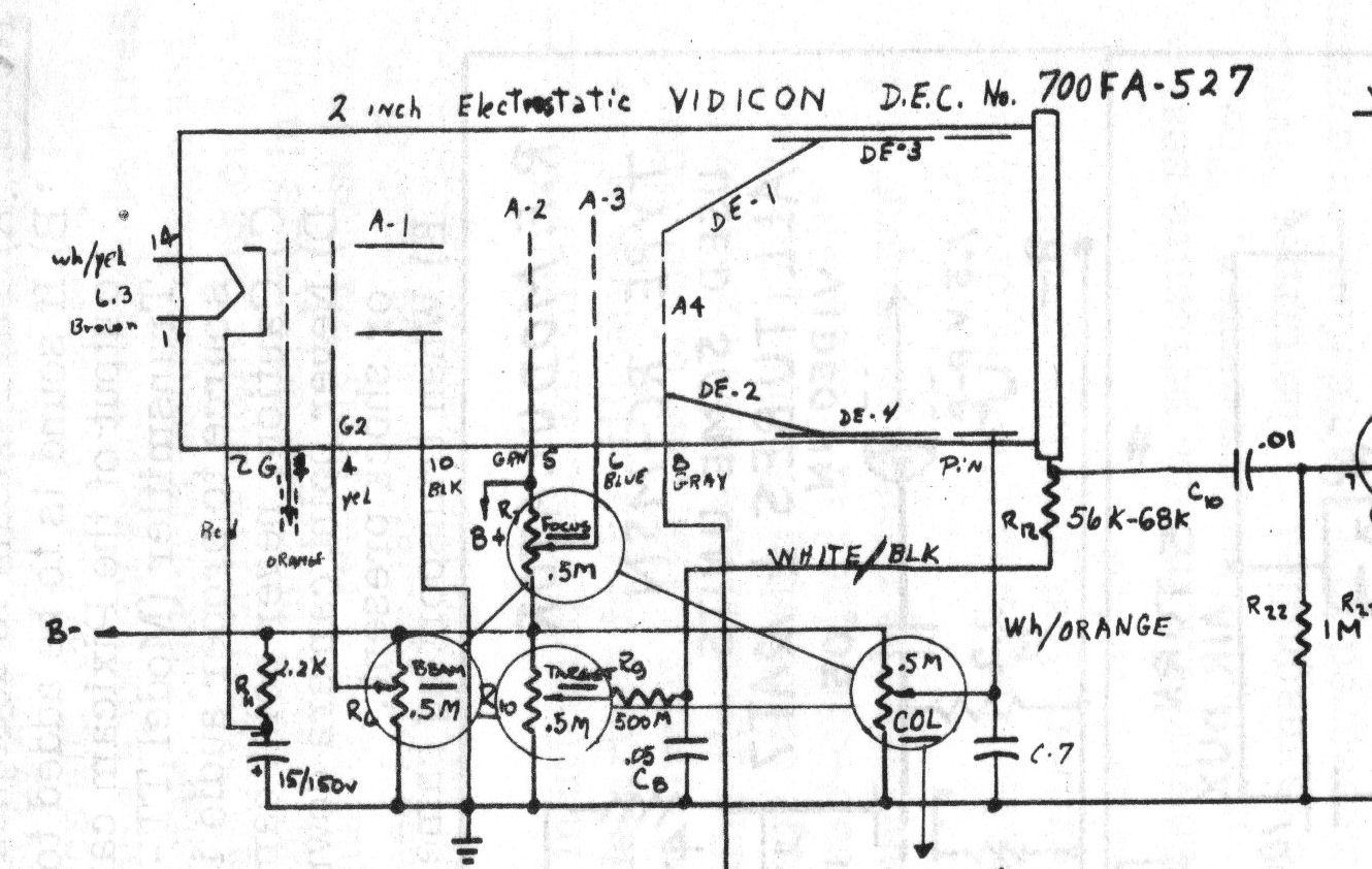
PIXICON CONTROLS - Beam, Target, Focus and Collimator - 20160816
The camera has two controls generally not found on conventional cameras and because of their special nature, a word of explanation is felt needed.
(1) Astigmatism control (R13) is located internally, top of chassis, #3 from front, which corrects for gun astigmatism and acts as a fine spot focusing control and is usually adjusted during the initial setup and testing of a particular electrostatic tube in the camera and does not normally require readjustment unless the camera tube itself is changed.
(2) Collimation control is provided on the rear panel to correct for the beam landing on the target surface. All other controls such as beam, target, focus, etc. are normal. The electron gun assembly is analogous to that used in conventional electrostatically deflected cathode ray tubes with several important differences.
An additional set of deflection plates have been added to improve deflection linearity, and astigmatism control is located internally to correct for gun astigmatism. An unusual type of electron gun assembly provides the high sensitivity and extremely fine spot for high definiton at low accelerated voltages. On the rear of the camera are located 4 controls whcih are the only ones which it is normally required to be adjusted during normal field use.
|