|
LabGuy's World: 'Tiny Ike' - Iconoscope TV Camera Project
PART TWO - DC POWER SUPPLIES. Providing the necessary voltages and meeting the power requirements. 
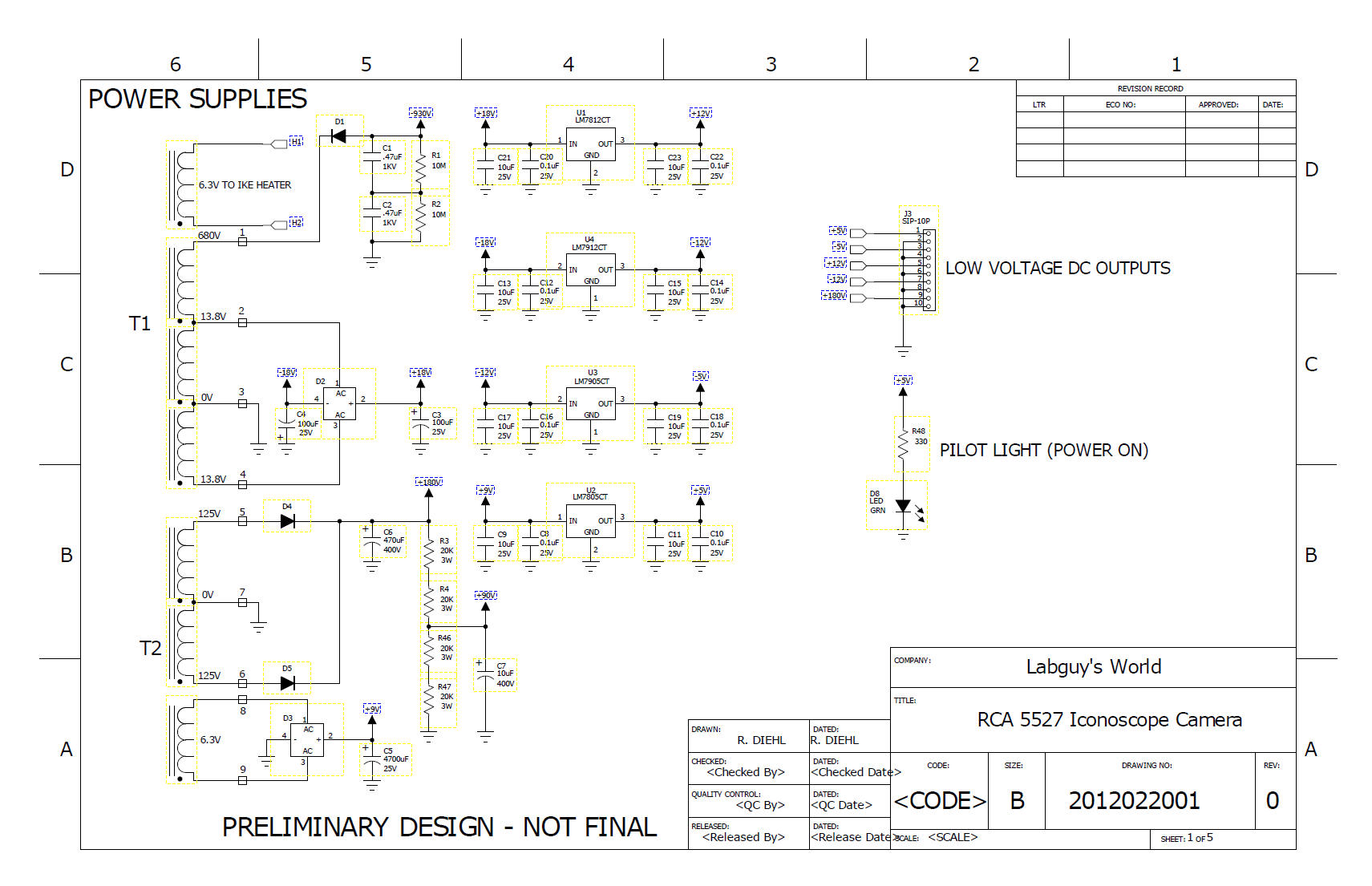
Nothing will operate without a power supply Using only two power transformers, I was able to design a supply that could provide over half a dozen voltages for the various circuits required in this camera. The larger transformer is from a scrapped Heathkit oscilloscope and generates the high voltage for the Ike electron gun, the 6.3 volts for the Ike heater and the +/-12 volt DC power rails for the low voltage circuits. The smaller transformer provides +180 volts for the deflection and blanking circuits as well as a second 6.3 volt AC winding. This winding is rectified, filtered and regulated to produce +5 volts. -5 volts is regulated from the -12 volt supply as its current requirements are minimal. Finally, a high(er) power voltage divider derives the +90 volts for the Ike's voltage divider chain. The AC input enters through the black box, lower left. This contains a standard three pin AC line cord entry jack, a line noise filter, a fuse and a power switch. All very conveniently in a single unit. The deflection, blanking and sync generator are just visible on the analog board in the upper right. 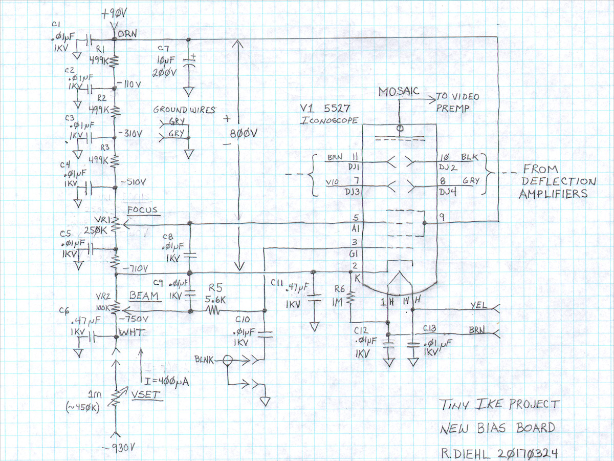
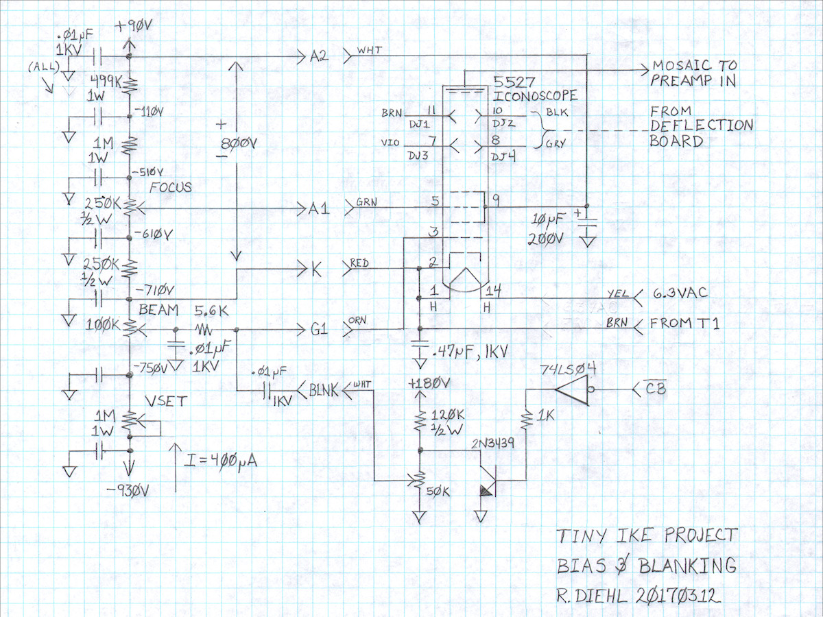
A practical Ike DC bias circuit - Revised: 20170324 (Original Schematic) The first step to bias this tube is to place 800 volts differential between the cathode (K) and the second anode (A2) of the 5527. This is set correctly by the VSET control at the bottom of the divider chain. Next, we assure that the control grid (G1) can go at least 40 volts more negative than the cathode (K). With a 100K pot, the BEAM control can set G1 from 0V to -40V relative to the cathode (K). (100K x 400uA = 40 volts) The focus anode (A1) is adjustable from +100V to +200V, relative to the cathode (K). Almost all points on the voltage divider are bypassed to ground via the ceramic 0.01uF, 1KV, capacitors. The +90 and -750 volt inputs have additional bypassing. +90V with 10uF and -750V with .47uF. The VSET pot is located outside the box on the DC power supply board. VSET and C6 form a very effective low pass filter. The wipers of the BEAM and FOCUS pots are bypassed to the cathode (K). Composite Blanking is AC coupled to the control grid (G1) via C10 and DC biased by way of R5. Blanking is delivered, via coax, from the analog board. The HV blanking amplifier will be covered on the blanking and deflection page. UPDATE: As of April 1, 2017, this project is complete. The final changes to this board were to add two .1uF, 1500V capacitors in parallel with C9 and C10. This improved the coupling time constant of the blanking circuit. The camera did not operate significantly different after this change. Why is the second anode set to +90 volts? This was done to accomodate the DC offset of the direct drive scan amplifiers used in my design. The 5527 deflection plates must be at or nearly the same voltage as the second anode, and vice versa, to prevent potentially defocusing the electron beam. Since the average DC output of the scan amplifier will be approximately +90, volts I lifted the second anode from ground by +90 volts to match. All the other divider chain voltages were adjusted accordingly. This is an excellent excercise in absolute versus relative voltage measurements and settings. The absolute, that is realtive to system ground, voltages are shown along the right side of the divider resistors. The relative voltage between second anode (A2) and the deflection plates (DJ1 - DJ4) is relatively zero volts DC and the 800 volts relative is shown between the +90 volt and the -710 volt points on the chain. [HOME] [ELECTRONICS PROJECTS] [TINY IKE INDEX] [PART 3] |