|
LabGuy's World: DEFLECTION YOKE AMPLIFIERS, Part 2
[HOME] [ELECTRONICS PROJECTS] [PART 1] 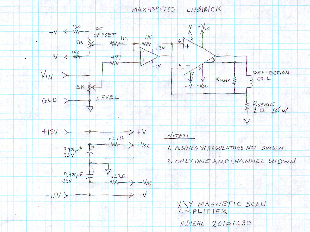
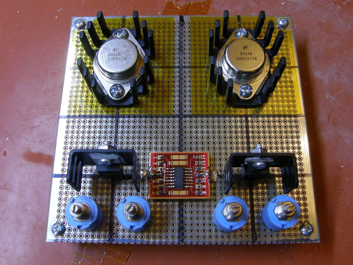
The new X/Y Magnetic Scan Amplifier Design and early construction - 20161230 After a two year hiatus, I am back to needing an amplifier capable of driving a magnetic deflection yoke. This is needed for testing the PhiloCam, my image dissector tube camera project, which is concurrent with this one. The unit pictured above was constructed over the four day Thanksgiving holiday break. (20161124 to 21061127) It is based upon the National Semiconductor LH0101CK power opamp. Capable of dissipating 60 watts, it can drive some hefty loads. The data sheet claims it can drive magnetic deflecion yokes. We will certainly find out soon enough. The first picture is of one channel of the amplifier. An input buffer stage provides level and offset controls. The output amplifier drives the deflection coil in series with a current sense ressitor. I designed the amplifier to have a 1:1 input voltage to output current conversion. One volt in gives one volt out with the input level control centered. I designed the input buffer to divide the input by two, via the level pot, and then boost it by two, with the first opamp, for a net unity gain. The DC offset control allows for input signals that are not bipolar or that have other DC offest issues. This amplifier could not be simpler. 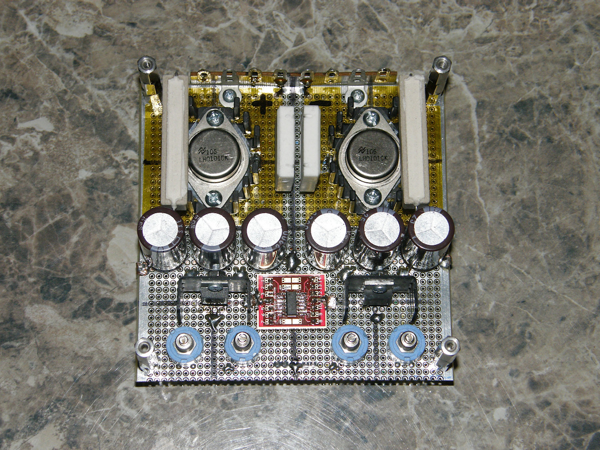
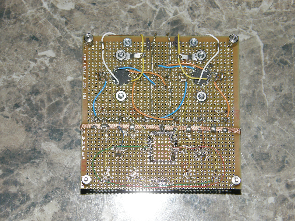
The final fully tested product - 20161230 I did not take any photographs during early construction. Instead, I shot a whole lot of video. But, here are a couple of photos of the completed and tested dual scan amplifier. The playlist of all seven parts of the video, so far, is provided below for your convenience. It is one hour of pure hard core prototype electronics construction. Even if it never works and that appeared to be a possibility for a while, you may pick up some skills simply by watching over my shoulder. You will see me make a horrible fundimental error that causes all kinds of difficulties that is not discovered until nearly the end. Hang in there because I demonstrate the rewards for unhinged levels of persistance. Watch as an electronic project organically evolves before your eyes. Necessity is a mother.. or something like that. These videos take you right up to physical completion. So, after 35 years in professional electronics, I should be giving back. So, my new probationary apprentice, pull up the tall stool, get a cup of your favorite beverage and get comfy! At the end of the videos, testing began... and immediately stopped! What I thought were silicone heat sink pads turned out to be a very thin sheets of aluminum faced with silicone on both sides. I used the 8 pin TO5 power opamp itself as the punch. I had no idea some, and it should have been all, of the pins were naturally shorted together. I have ordered the correct mica insultors for these parts and that should not be a problem again. 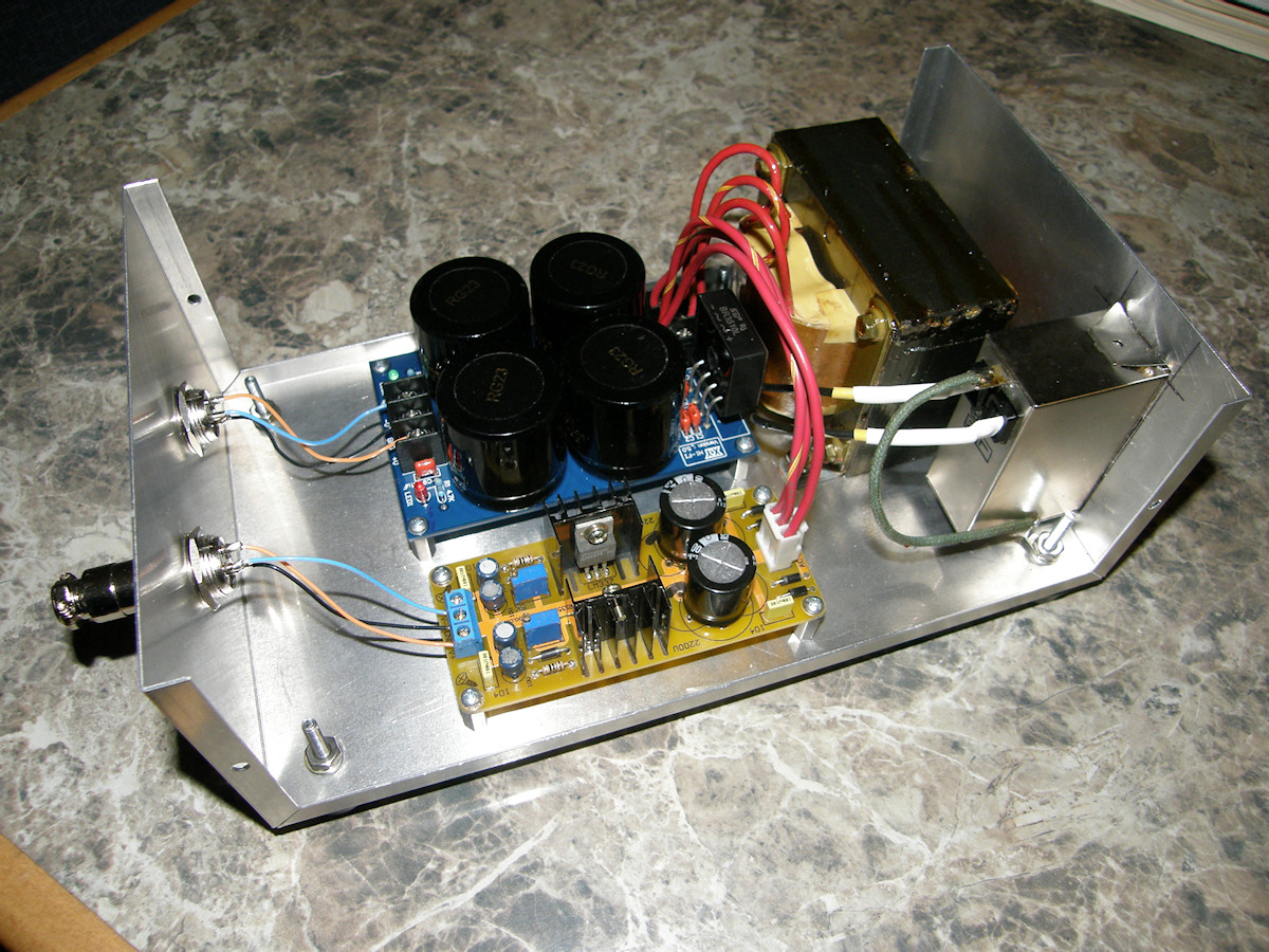
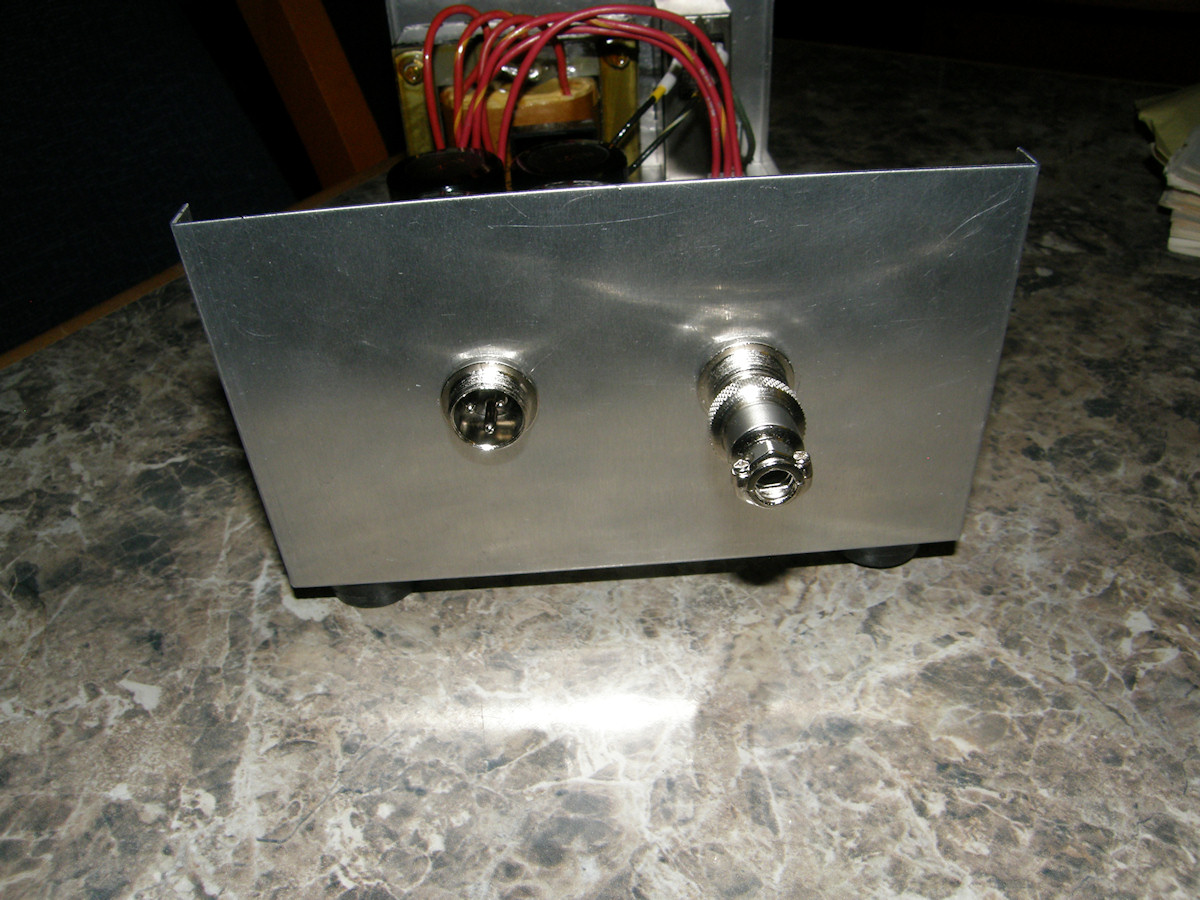
The DC power supply completed - 20161211 A power amplifer needs a power supply, of course! So, here is the power supply in its completed form. The jack on the left provides unregulated plus and minus twenty two volts unregulated at up to 3 amps. The other jack provides regulated plus and minus fifteen volts at up to 1.5 amps. This second power supply is adjustable from 1.2 to about 18V on each polarity separately. Total power load for this supply is 90 watts maximum. VIDEO: Let's build a power supply (multi-part playlist)- 20161226 Here is the YouTube video playlist of the power supply. This is another successfully completed project. REFERENCES: 1. PDF file [LH0101] 60W high power opamp [HOME] [ELECTRONICS PROJECTS] [PART 1] |