| LabGuy's World: B&K
Television Analyst Model 1077B
UPDATE INFO & PHOTOS! 03.01.26 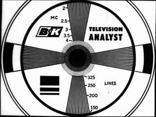 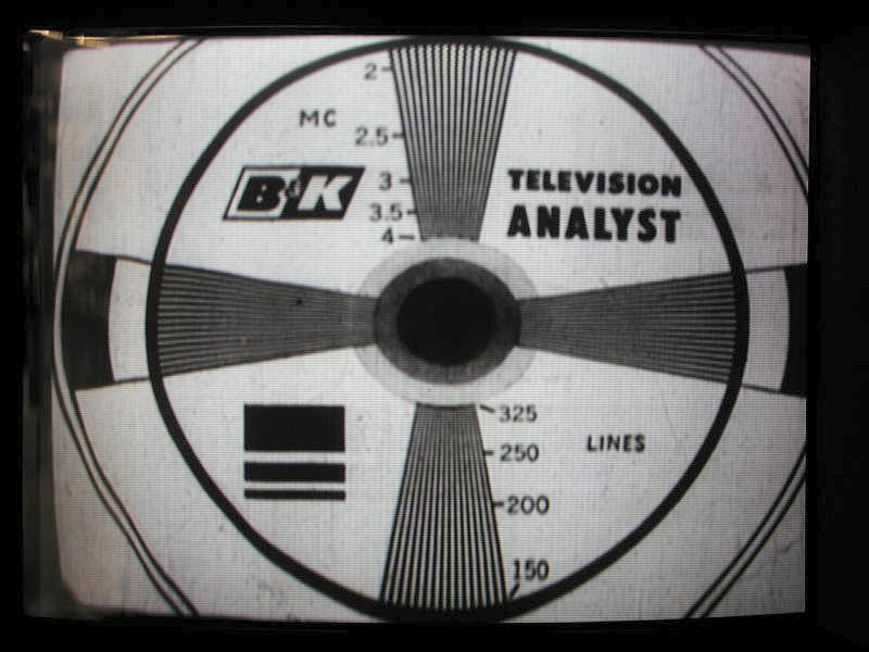
1077B "TV Analyst" Test Pattern Slide and Screen Shot These were used in tv repair stores and high school electronics classes. A product of the early 1970s. They were be used to test many of the television receiver's subsystems, such as: the tuners, IF stages, video amplifiers, high voltage power supply and deflection circuits. The 1077B as also an excellent teaching tool. All in all, this is a fabulous piece of gear! The best part was the test pattern generator! The second photo, above, is a contemporary shot of the 1077B video output as displayed on Sony broadcast quality monitor. The vertical linearity distortion is occurring in the 1077B, and not at the monitor. Such is the result of tube circuits and old dried out capacitors. Stay tuned for restoration updates as time permits! 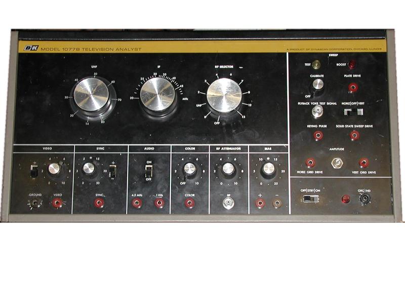 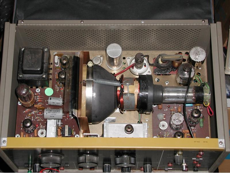
Front and top views of the 1077B TV Analyst. (New photos 03.01.27!) The B&K television analyst is also a "video camera" of sorts. At the least it's a "video source". It contains a clever system called a Flying Spot Scanner, or FSS . An FSS uses a 5 inch diameter CRT (Cathode Ray Tube), visible in the second photo above, and a PMT (Photo Multiplier Tube) visible on the left side of the same photo. A transparent slide, visible in the photo below, is pressed tightly against the face of the CRT. The CRT is scanned with a blank raster. The light from this raster is passed through the slide and is picked up by the PMT where it generates a video signal. This is the method of scanning that was used in the earliest days of television and works extremely well. Another feature of the flying spot scanner is that is elagently simple. Looking in the top of the unit, you can clearly see that there is not much to it. The circuits of this FSS also serve as a source of signals that can be fed into various TV circuits to locate a fault. Thi includes, horizontal and vertical scan signals, raw video and sync and various signals for testing the (radio) receiver portion of a TV set. 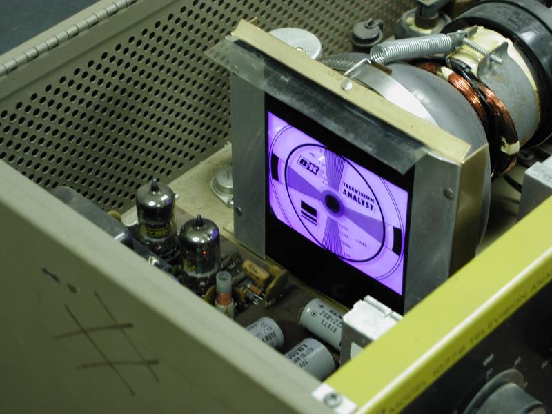 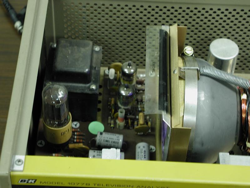
Short Persistence Ultraviolet Phosphor CRT! (New Photos! 03.01.26) The scanning CRT uses a short persistence ultraviolet (UV) phosphor. The test pattern slide pressed to the front of the CRT in the first photo above. The second photo shows clearly, the RCA 931 photomultiplier tube (PMT with the light brown base) directly in front of the scanning CRT. The PMT converts light into electrons and then amplifies these electrons thousands of times. The PMT is more sensitive to UV light than to visible light. This makes for a very sensitive system. The short persistence of the phosphor is necessary to increase the horizontal resolution of the image. NOTE: The flying spot scanner doesn't actually work with the top cover open! Room light over powers the light produced by the CRT. . UPDATE! 03.01.04: Need parts and service on your old B&K Precision test equipment? Then visit this site here: B&K Test Equipment - The World's #1 source for older B&K Precision test equipment, charts & parts. Also specializing in repair & service on all older B&K equipment. They sell slides and tubes for the 1077B and all its variations! The service package that I purchased from B&K Test Equipment lead directly to the successful resurrection of y 1077B! Thanks!!! When you visit their site, be sure to tell them LabGuy sent you! [HOME]......[MUSEUM OF EXTINCT VIDEO CAMERAS] Last updated: January 06, 2005 |