LabGuy's World: KJ6RNL Amateur Television in San Jose, California
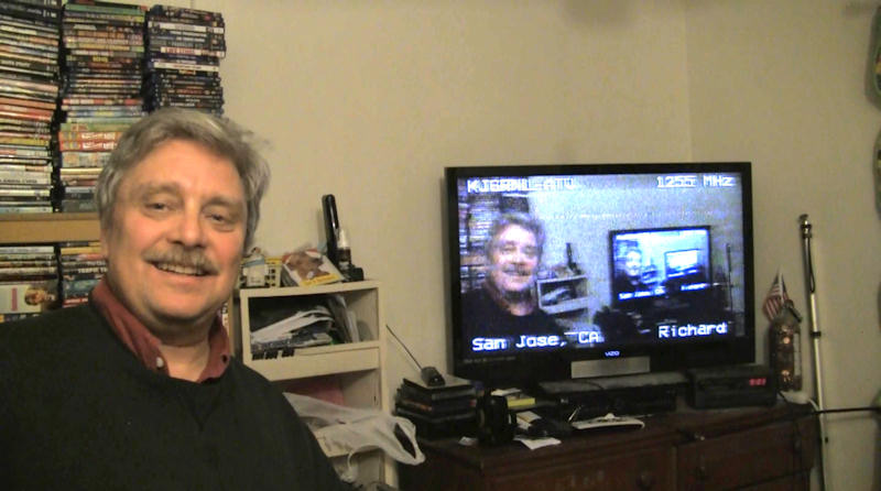
Labguy, KJ6RNL testing his early ATV transmission December 28, 2011 PROJECT GOAL: Construct a two-way amateur television tranceiving system for use with the [K6BEN] ATV repeater in San Jose, California. Keep it simple and keep it cheap (as possible). Visit the [K6BEN] web site for the particulars about the repeater and the club. Of course, be certain to have the appropriate federal ham radio license. Visit the [Amateur Radio Relay League] to learn all about amateur radio, an excellent hobby. This article will be describing the KJ6RNL station equipment that was successfully assembled for this purpose. 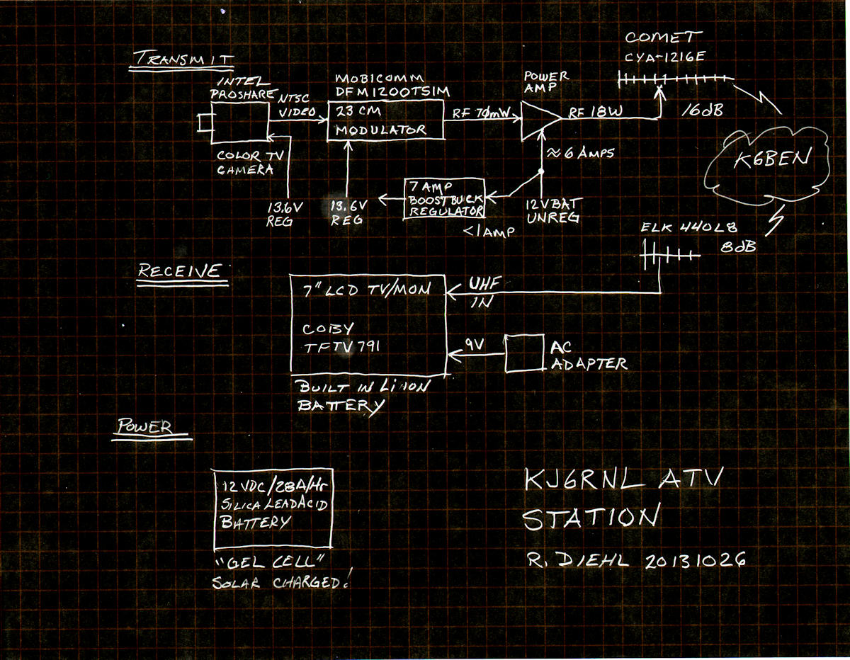

Block diagram and actual KJ6RNL ATV transmitter It is relatively simple to operate amateur television here in San Jose, California, heart of the Silicon Valley. The repeater is located on top of Mount Loma Prieta. Yep, the mountain famous for the San Francisco bay area earthquake that occured on October 17, 1989. The repeater is at an altitude of 3,864 feet giving wide coverage to most of the south San Francisco bay area and areas to the west and south like Santa Cruz and Monterey. If you can see the top of Loma Prieta from your QTH, then you can get into this repeater. The diagram above represents just about the simplest system one could construct. Video starts from a common video camera, is FM modulated onto a 1,255MHz radio carrier wave, boosted up to 18 watts and transmitted from a reasonably compact roof top high gain yagi antenna. The receiver is as simple as any cable ready TV set and another small antenna tuned for the 440MHz band. Now, referring to the second photo above... Item 1 is the main DC power distribution box. It houses ten pairs of parallel wired banana jacks. This box is connected to the 28 amp hour gel cell via two 16 gauge wires bound in nylon spyral wrap. An excellent flea market find! AS in all of my projects, scrounging is highly encouraged! Beg, borrow or steal - figuratively speaking of course! Seek out local amateur radio hams. These folks will hook you to a network of folks that can find anything, anywhere, anytime. Item 2 is the RF power amplifier with a heat sink and cooling fan. The most expensive piece of the project. This one cost me $600 to build. But, if you shop carefully, it can be built for around $300. Item 3 is the FM video audio modulator. I obtained this one from Ebay for about $110. Again, judicious shopping online can turn these up for as low as $59. Item 4 is the boost buck voltage regulator. Its job is to take the constantly changing voltage of the battery and deliver a constant 13.8 volts, regardless of the battery voltage. Here is why we need to do this. THIS IS CRITICAL. The 12 volt regulators in the camera and the modulator will NOT work correctly with an input lower than 13.2 VOLTS! The modulator contains a type 7812 series pass voltage regulator. It provides a very accurate 12 volts only when its own input is at least 1.2V higher than the output. That's 13.2V minimum input voltage! I set the boost/buck regulator for a comfortable 13.8 volts output. The battery will range from about 12.6 volts at the start and sag to 10 volts when depleted. The boost buck regulator accepts an input voltage of ten to fifteen volts and then provides a constant 13.8 volts for the camera and modulator. This one is rated at seven amps or about 100 watts. Item 5 is my handheld UHF radio used for the voice portion of the QSO. It is common practice for one person to transmit video and the group chats about the image subject via two meter or UHF FM voice. We take turns transmitting television and commenting one each others signals. 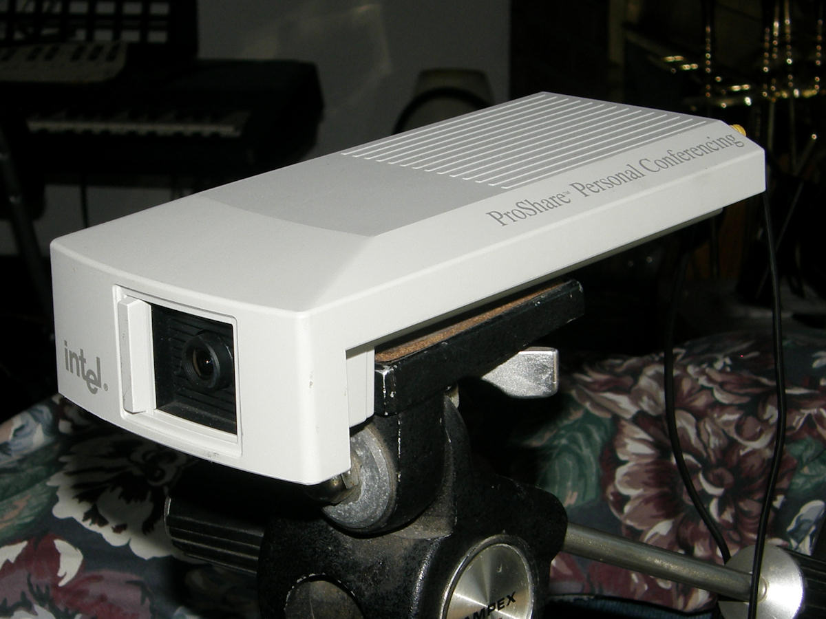
COLOR TV CAMERA Almost any common standard definition television camera may be used with the modulator. Black and white cameras are OK too. Some folks use their tired and worn out camcorders for the camera function. This camera runs on 13.2V at approximately 300mA. It is fixed focus and otherwise fully automatic. I like this camera because it has several less adjustment we have to deal with. The trade off is a slightly lower quality image. Mostly with overly bright objects in the scene. These tend to overdrive the modulator and cause on the air distortions. And, to a lesser degree, the lens has a bit of spherical aberation. It makes a fish bowl kind of image. But, its fine for "talking head" and close up demo shots. Of course, your video does not absolutely have to be generated by a camera. The source could be a PC, VCR or DVD playback, a flying spot scanner or even a monoscope, a kind of camera with one built in image. Think Indian Head test pattern. Speaking of cameras, some digital still cameras have an SD (standard definition) video output as well. You could transmit "slide shows" with this method. In the first photo at the top of this article, I was using my HD camcorder's SD monitor output. This is how I got the more advanced wide screen video. Most SD is in the standard 4/3 aspect ratio instead of the HD 16/9. 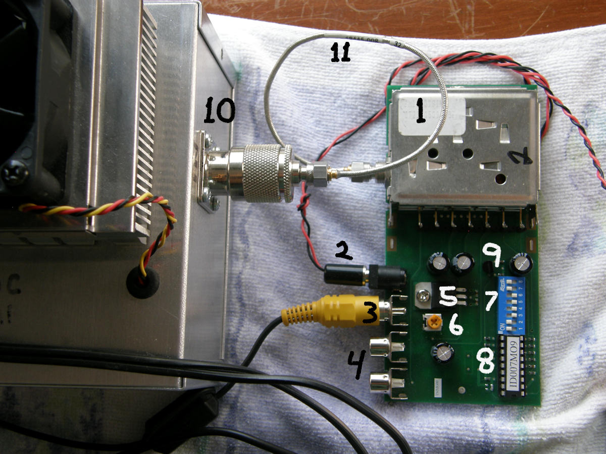
FM VIDEO AUDIO MODULATOR There is a lot happening in this photo. Number 1 is the actual prefabricated RF modulator unit. Manufactured by [Comtech Technology] in the UK. The "ready to use" green board assembly is made by [MobiComm Communications] in the Netherlands. They sell these on Ebay under the seller name, "gnupic" for $109. (as of Oct. 2013) It takes video and two channels of audio in and puts out a fully modulated RF signal in the 23cm band. Output power is between 50mW and 70mW, depending on the termination impedance. Item 2 is the 13.6V DC power input. Again, not 12 volts. This voltage must be above the voltage drop of the 7812 type analog regulator. Number 3 is the video input coming from the camera. Number 4 are the two unused audio inputs. Number 5 is the 7812 voltage regulator mentioned previously. Number 6 is the video input level control. This adjusts the FM deviation of the modulator. Adjust for best picture. Number 7 is the PLL frequency select switches. There are 256 setttings possible covering a range of 1240.0MHz to 1303.75MHz in 250KHz steps. Number 8 is a tiny computer that reads the switches and sends the appropriate digital pulse to the modulator to set the phased lock loop (PLL) to the correct frequency. Number 9 is tiny 5V regulator for the computer chip. Number 10 is the input to the power amplifier. Number 11 a short piece of flexible hard line coax terminated in SMA connectors. DATA SHEETS:[PDF of DFM1200TSIM module] and [PDF of the Comtech 23cm modulator] 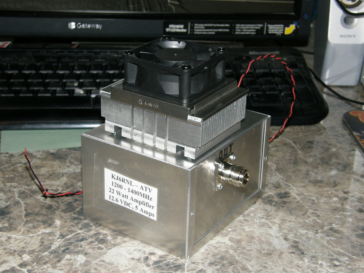
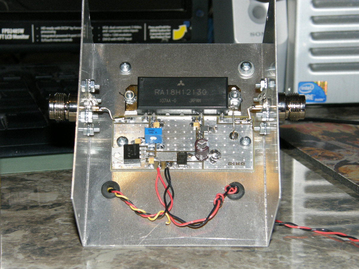
RF POWER AMPLIFIER The power amplifier is built around this pre-fabricated RF amp module, model amp1200hp sold by RF-Links. This is available from several manufacturers. Price ranges between $250 and $499. Of course, I found the latter before the former. This is the most expensive part of the system. The case is a simple aluminum project box. I used a chassis punch to make the holes for for the N connectors. The heat sink and fan are for a Pentium chip. The big "IC" on the board is buttered with heat sink compound and coupled directly to the inside of the box. The heat sink and fan are also buttered up and mounted to the outside of the box. The heat couples through the wall of the box very efficiently. It operates on unregulated 12 volts DC and pulls about five amps of current when producing an output power of 18 watts. I have replaced the red and black power wires with a much heavier gauge and shorter leads since the photos were taken. Those first wires were running hot. DATA SHEETS:[PDF of a 22 watt power amplifier module]. This module is exactly the same, in terms of operation, as the one I purchased. The user must mount the power chip for proper heat dissipation, attach power leads to the PCB and provide the appropriate input and output connectors. 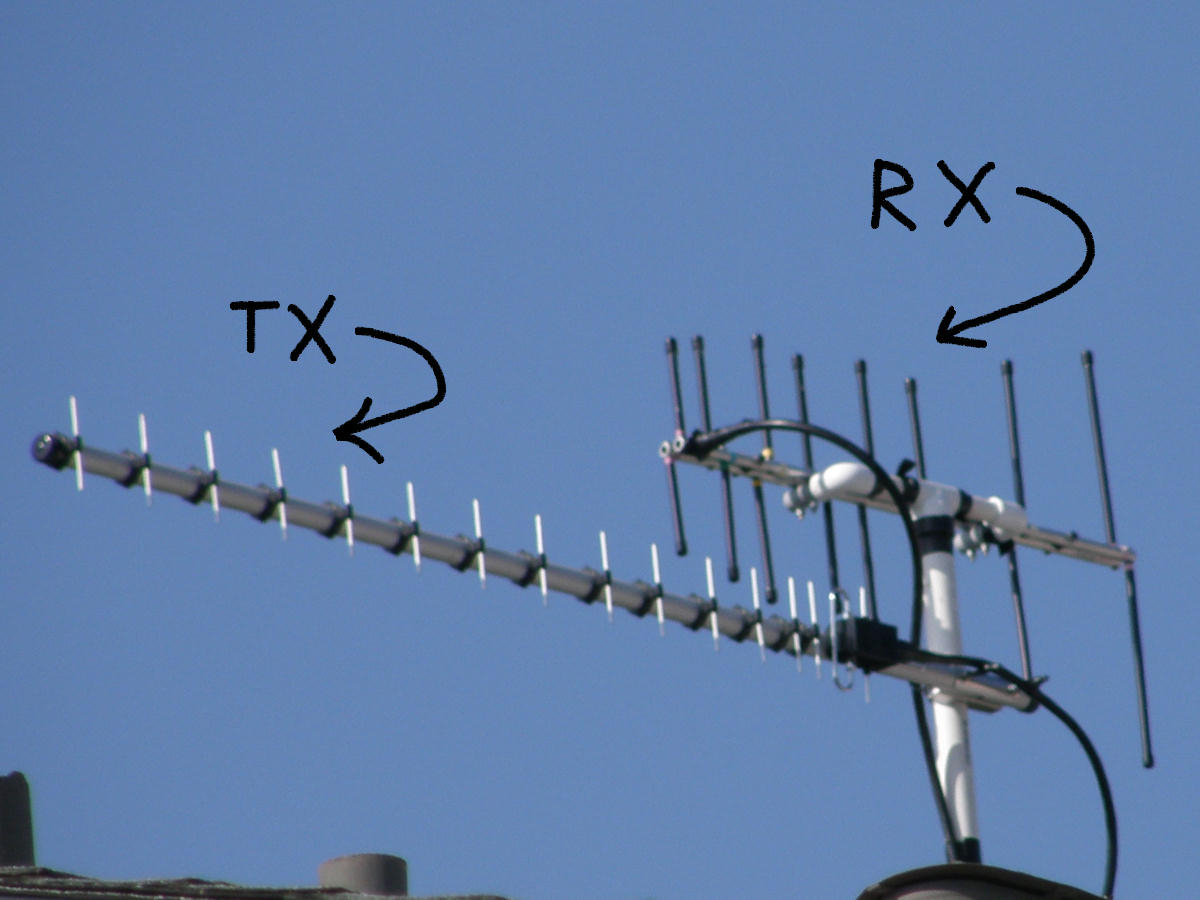
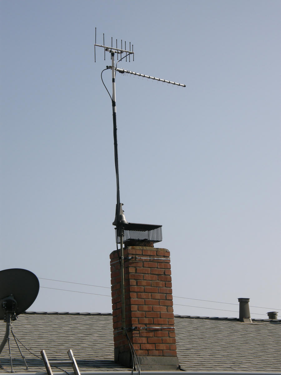
TRANSMIT AND RECEIVE ANTENNAS Because the repeater operates in two different bands, we will need two antennae. Also note the position of the antennae. They are "on edge" because we operate ATV with vertical polarization. Normal TV antennae are operated "flat" for horizontal polarization. We transmit to the repater, as previously mentioned, on 1255MHz FM and we receive back on 427.25MHz or CATV channel 58. Not UHF 58. My transmit antenna is the Comet CYA-1216E which has a very tight beam angle and well over 16dB of gain. The receive side antenna is an Elk 440L8 with 8dB of gain. Place your antennae as high as possible. Try to go over any obstacles like buildings and trees. I am lucky to live on the east side of the valley, up the hill about four or five hundred feet above the valley floor. The repeater sits in a direct line of sight due south from my QTH about 20 miles. My antennae are at least 35 feet above the mean street level in front of the house. This completely clears the top of all of the large trees that have been a problem since I started running ATV. After testing in clear weather, I have a proven P5 signal path. The Comet antenna cost approximately $130 ordered on line. The Elk antenna was purchased at Ham Radio Outlet for about $110. MORE INFO:[ Google search for Comet CYA-1216E] [ Elk 440L8] 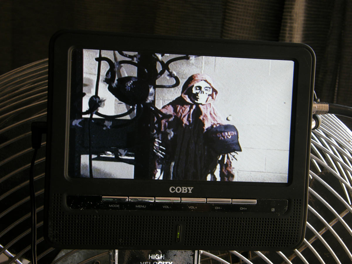

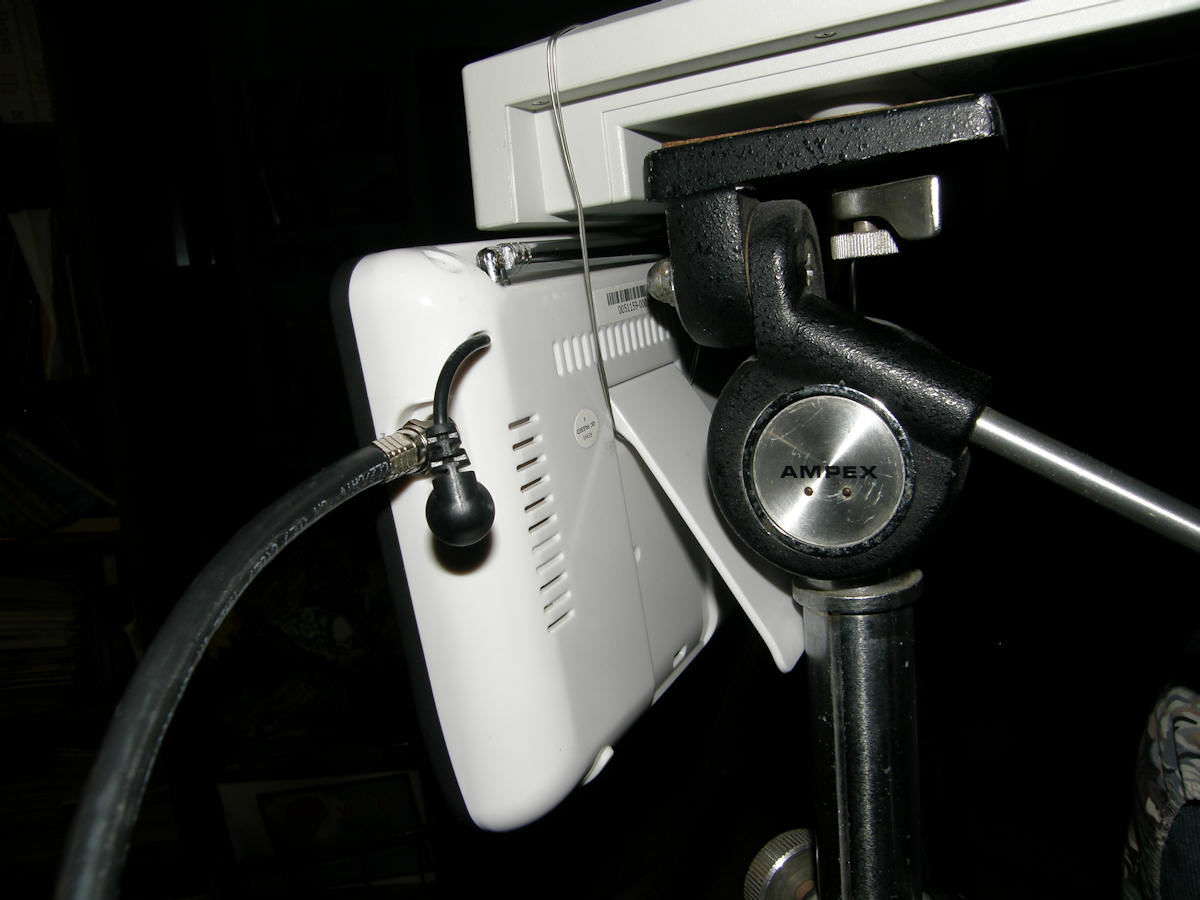
ATV TELEVISION RECEIVER - Nothing special really On the left, the ATV club members are currently decorating the repeater building for Halloween. On the right, is W2NYC speaking to me during the Wednesday night ATV net, back in December of 2011, as viewed on the 42 inch HDTV in my bed room. Just about any television receiver can be used for ATV. It must have a "cable ready" tuner. That is the "CATV" mode in the set up menu. This includes the TV tuners in computer video capture cards and VCRs. So, if your TV lacks the proper tuner, an old VCR will work perfectly in its place. Plus you can record what you are receiving. The portable 7" LCD set was purchased for about $60. The right hand photo is my regular big screen TV. Set the TV to CATV mode and select channel 58. Plug the receiving antenna into the RF input jack (F fitting) and you're ready to go. 
RECEIVING ATV ON A HAND HELD POCKET TV! Certain pocket televisions can receive the repeater directly on their small whip antennas! This one is my personal Casio TV-880. It is remarkably sensitive. I have received the repeater at a range of over 25 miles on this little guy! It picks up ATV anywhere in San Jose and the surrounding communities. This is great for performing an initial site survey to verify you have line of sight with th repeater. Some folks are unlucky and have trees, structures or hills in the way. Such is amateur radio! Many members of the Silicon Valley ATV group operate mobile television from their vehicles or from equipment lugged about in milk crates for ham radio field day events. UPDATE 20131201: I recently found a discussion on this television's ability to pick up ATV directly on the UHF band. It is not because it is an excellent receiver. Just about the opposite. It was hypothesized that the TV's tuner has poor IF image rejection. Instead of detecting the signal approximately 41.75Mhz above the local oscillator, it is actually picking up the unwanted mixer product 41MHz below the local oscillator frequency! (The 440MHz ATV band lives just below TV channel 14 on the UHF dial) In this case, a deficit becomes a benefit! I just purchased two more of these Casio TV-880s for less than $20 each including the shipping! 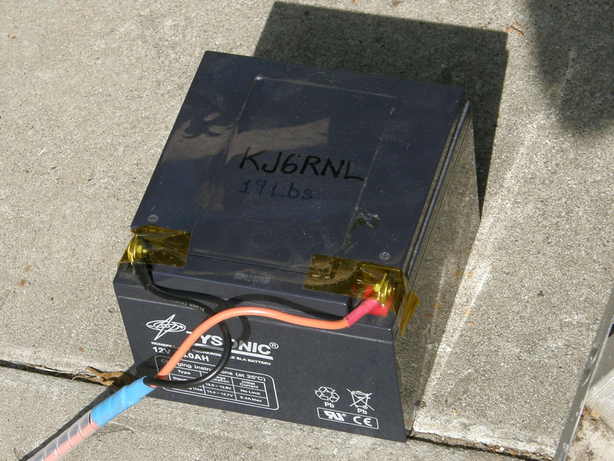

DC POWER SOURCES For the station I have just described, I use a large twelve volt silicate lead acid battery for portable operation. Also known as a gel cell. This one is rated at 28 Amp hours. That is enough power for at least two solid hours of video transmission. It is then recharged on AC power or my preferred method of using solar panels which recharge in about eight hours of strong sun light. As a warning, I wrote the weight of the battery on top so a person may be forwarned of possible back injury. This sucker is heavy and dense. Lifted carelessly, it could result in a serious injury. In the photo below, we see my 12 volt 25 amp AC power supply which also powers this station. The AC power supply is larger and heavier than the battery and is far less convenient to lug around. 
AC POWER SOURCES Safety considerations. The big issue here is with the low voltage and high current. Unlike high voltage, there is no shock hazard to speak of. However, with high currents like this (100 amps+ from the battery alone) you can get severely BURNED and/or start a FIRE! The AC supply, at only 25 amps capability, will dump 300 watts of power into the wiring should it become shorted. The battery will dump a whopping 1,000 watts or more! Fortunately, this supply has built in automatic short circuit protection. But, never rule out Murphy's law when it comes to safety. There is so much power available the copper wires can instantly melt. The melting wires will short other leads, doing more damage, or could burn a person. Burning plastic insulation can give off thick hydrocarbon smoke and other highly toxic gases. Phosgene, a serious nerve destroying agent, is one gas released by burning PVC. This is especially dangerous indoors where the gases can become concentrated. High current is, in many ways, far more hazardous than high voltage. 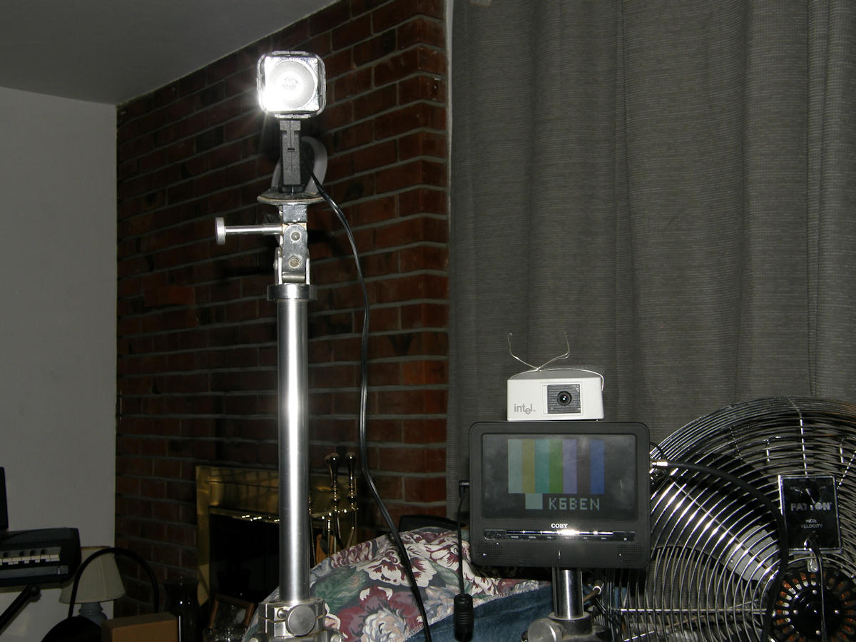
OPERATING PRACTICES To begin with, you must hold a currently active amateur radio license. A technician class or higher license is required. Watch your local paper or check the web sites for "ham crams" being held in your area. These are one day events where the material is studied in a marathon session. It is actually much easier than it sounds! The actually license exam is given in the late afternoon. Success rates are as high 80 to 90% in some cases. I passed the techncian class test first try. Upgraded to my general class license less than a year later by the same method. 
QUICK AND SIMPLE CALL SIGN VIDEO I.D. - EXPRESS YOURSELF - HAVE FUN When operating on air, it is required that the operator send his call sign every ten minutes. This includes a visible label in the video and a call out on voice. This can be a simple hand written sign or video character generator. I personally use both methods depending on the moment. 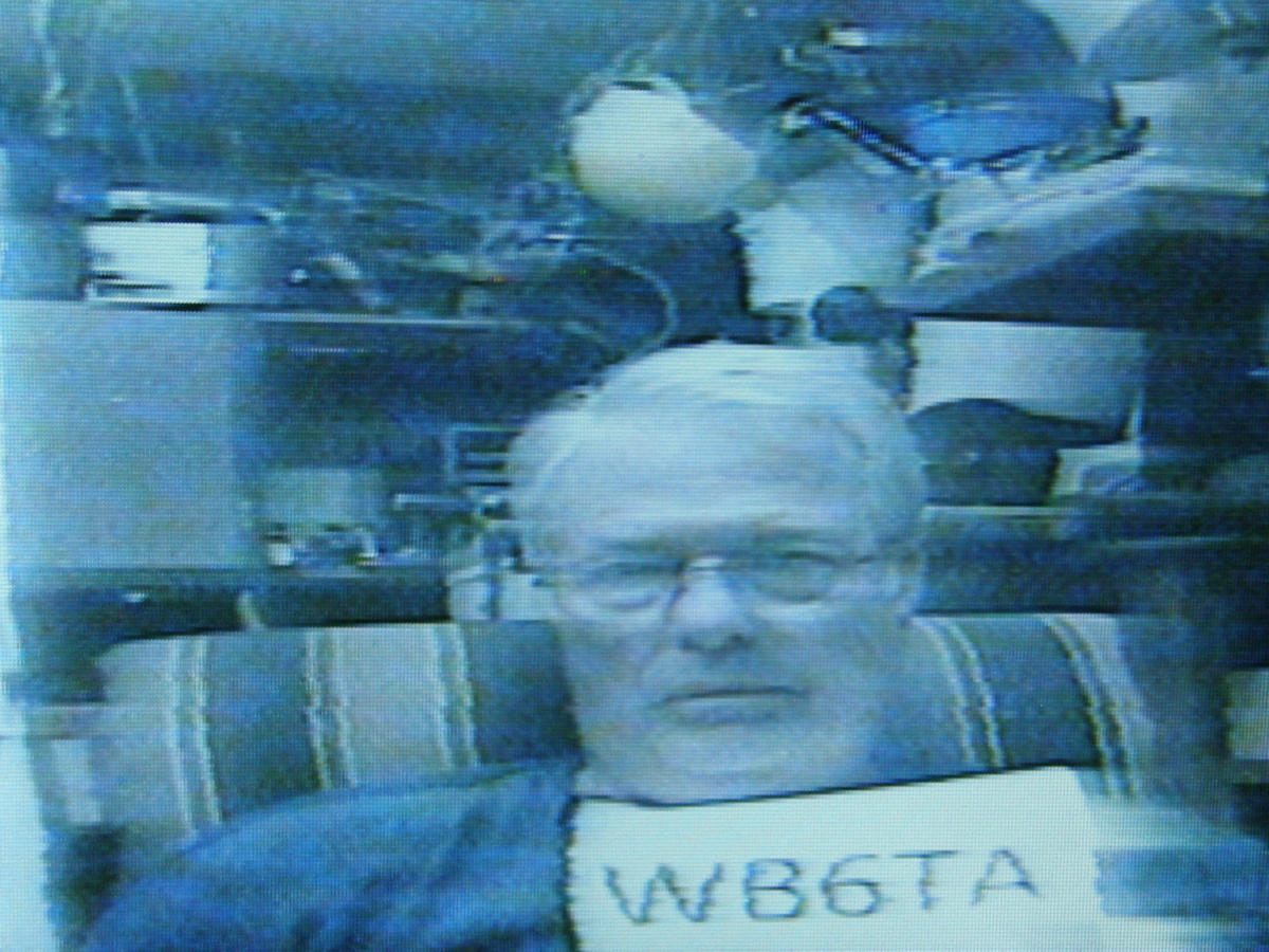

SOMETIMES WE SEE A NEW FACE FOR THE FIRST TIME! (2013-11-27) This past Wednesday evening, we saw a new face on the weekly ATV net. Welcome Terry, WB6TA, from Hayward! You had a great picture. So, I snapped some photos for the old album. Terry's transmitter and amplifier look strikingly familiar! Congratulations to Terry, WB6TA for his successful operation. Looking forward to meeting you at our monthly luncheon! Some folks have nice built-in operating positions. Some people who are renters and apartment dwellers are more limited. As a renter, I built my system as portable and compact as possible so that it can be set up and taken down, only creating clutter when I am operating. In fact, my whole station packs into a small cardbox when not set up. My landlord and room mate approves! As seen in the earlier photos, my operating position is very basic. Two tripods, a photo light, a camera, TV monitor and, of course, A HAM. The transmitter sits atop a small end table, the power source beneath, when in operation. That's all there is to it! If you live in San Jose, have an amateur radio license, and have not gotten on the air, why not? Hope to see you on the [San Jose, Wednesday night ATV NET]! [HOME] [ELECTRONICS PROJECTS] Created: October 23, 2013, Last updated: December 3, 2013 |